EP4501209A2 - Systèmes et procédés d'alignement de l' il pour imagerie oculaire - Google Patents
Systèmes et procédés d'alignement de l' il pour imagerie oculaire Download PDFInfo
- Publication number
- EP4501209A2 EP4501209A2 EP24215245.2A EP24215245A EP4501209A2 EP 4501209 A2 EP4501209 A2 EP 4501209A2 EP 24215245 A EP24215245 A EP 24215245A EP 4501209 A2 EP4501209 A2 EP 4501209A2
- Authority
- EP
- European Patent Office
- Prior art keywords
- subject
- eye
- alignment
- light
- baffle
- Prior art date
- Legal status (The legal status is an assumption and is not a legal conclusion. Google has not performed a legal analysis and makes no representation as to the accuracy of the status listed.)
- Pending
Links
Images








Classifications
-
- A—HUMAN NECESSITIES
- A61—MEDICAL OR VETERINARY SCIENCE; HYGIENE
- A61B—DIAGNOSIS; SURGERY; IDENTIFICATION
- A61B3/00—Apparatus for testing the eyes; Instruments for examining the eyes
- A61B3/10—Objective types, i.e. instruments for examining the eyes independent of the patients' perceptions or reactions
- A61B3/14—Arrangements specially adapted for eye photography
- A61B3/15—Arrangements specially adapted for eye photography with means for aligning, spacing or blocking spurious reflection ; with means for relaxing
- A61B3/152—Arrangements specially adapted for eye photography with means for aligning, spacing or blocking spurious reflection ; with means for relaxing for aligning
-
- A—HUMAN NECESSITIES
- A61—MEDICAL OR VETERINARY SCIENCE; HYGIENE
- A61B—DIAGNOSIS; SURGERY; IDENTIFICATION
- A61B3/00—Apparatus for testing the eyes; Instruments for examining the eyes
- A61B3/0008—Apparatus for testing the eyes; Instruments for examining the eyes provided with illuminating means
-
- A—HUMAN NECESSITIES
- A61—MEDICAL OR VETERINARY SCIENCE; HYGIENE
- A61B—DIAGNOSIS; SURGERY; IDENTIFICATION
- A61B3/00—Apparatus for testing the eyes; Instruments for examining the eyes
- A61B3/0091—Fixation targets for viewing direction
-
- A—HUMAN NECESSITIES
- A61—MEDICAL OR VETERINARY SCIENCE; HYGIENE
- A61B—DIAGNOSIS; SURGERY; IDENTIFICATION
- A61B3/00—Apparatus for testing the eyes; Instruments for examining the eyes
- A61B3/10—Objective types, i.e. instruments for examining the eyes independent of the patients' perceptions or reactions
- A61B3/12—Objective types, i.e. instruments for examining the eyes independent of the patients' perceptions or reactions for looking at the eye fundus, e.g. ophthalmoscopes
Definitions
- manual handheld fundus cameras require the operator to manually position a camera in three-dimensional space along 6 degrees of freedom, and often require an integrated screen to view the eye, while the head of the subject is partially restrained leaving 3 degrees of freedom, for a total of 9 degrees of freedom.
- Traditional manual desk-mounted fundus cameras require the operator to manually steer the camera with a joystick, 6 degrees of freedom, while the subject's eye is restrained with a chinrest and headband as well as fixation, leaving 6 degrees of freedom in total.
- Automated or semi-automated fundus cameras require complex motors, additional cameras and sensors, and built-in image processing to drive the automated alignment along 6 degrees of freedom, thereby adding significant cost, and also restrain the subject's eye using chinrest, headband and fixation.
- the human eye is the endpoint for a highly versatile cybernetic system that can align the optical axis of the eye with respect to external objects along 6 degrees of freedom. Because there is a need in the art for an alignment system with reduced cost, complexity, and ease of operation, it is attractive to use the natural alignment of the human body.
- the implementations comprise one or more guide lights and one or more baffles configured to mask the one or more guide lights from the subject's eye such that the one or more guide light is only visible to the subject when the optical axis eye of the subject is aligned with the optical axis of an ocular imaging system along one or more degrees of freedom.
- a device for aligning the optical axis of a subject's eye with the optical axis of an ocular imaging device comprising a housing, the housing comprising a first end, a second end, an outer surface, and an inner surface, wherein the inner surface defines a luminal space and wherein the luminal space is configured to allow for passage of the optical axis therethrough; a plurality of guide light assemblies disposed within the housing, each guide light assembly comprising a body, the body comprising a first side and a second side opposite the first side, wherein the second side faces the luminal space a channel defined in the body, wherein the channel extends from the body first side to the body second side, wherein the channel forms an opening in the body second side; a guide light disposed within the channel, wherein the guide light is configured to emit rays out of the opening; and a baffle disposed transversely in the channel between the guide light and the opening and configured to mask rays from the guide light, wherein the baffle further comprises
- a method of aligning the optical axis of a subject's eye with the optical axis of an ocular imaging device comprising providing a first set of guide lights along the line connecting the optical axes of the subject's eye and of the ocular imaging device; and providing one or more baffles, configured to mask the rays emitted from first set of guide lights from view of the subject such that first set of guide lights is only visible to the subject when the eye of the subject is aligned with the optical axis of an ocular imaging system.
- the instant disclosure relates to optical imaging system embodiments for imaging the eye of a subject which allow a subject to properly position and align the optical axis of his eye with the optical axis of an ocular imaging system in response to visual cues from the system.
- This is in contrast to known optical imaging systems where the subject's eye position is fixated as much as possible and alignment is achieved by adjusting the position of camera elements with respect to that eye.
- the disclosed implementations utilize the precise oculomotor alignment system of the human eye to align to the optical axis of the imaging system, instead of relying on the trained operators or expensive servo motors to align the optical axis of the imaging system to that of the human eye.
- the disclosed systems are further able to provide for precise oculomotor alignment without the use of mirrors or lenses to direct light to the desired angle along the optical path.
- the system comprises a camera (for example a fundus camera) having an image sensor and one or more guide lights positioned laterally between the image sensor and the subject's eye.
- the system further comprises one or more baffles positioned between the one or more guide light and subject's eye.
- the one or more baffle is configured to occlude the subject's view of the one or more guide light until the eye of the subject is properly positioned and aligned translationally (along x, y, z axes).
- Further embodiments have additional lights to provide for alignment rotationally (along ⁇ , ⁇ , and ⁇ axes) with respect to the optical path of the imaging device, resulting in optimal image acquisition.
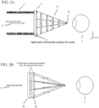
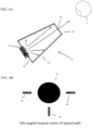
- the guide light is a ring light 4, which is a light forming a substantially ring-like shape.
- the guide light 4 is masked by a baffle 10, which, according to certain embodiments, is of a substantially cone-like shape with the wide end 12 of the cone-like shaped baffle 10 at the ring guide light 4 and the narrow end 14 near the eye of the subject 2.
- a coaxial light 8 becomes visible to aid in coarse alignment of the subject's eye 2 with the system. As the subject directs its gaze into the device, some section of the guide light ring 4 comes into view.
- the subject As the subject further adjusts its gaze toward alignment, more and more of the ring 4 becomes visible until the entire ring 4 is visible indicating that the subject's optical axis 11 is in alignment with the to the optical axis of the imaging system 13 has been achieved.
- the aspect of the ring 4 that is not visible will direct the subject to adjust its eye 2 in the appropriate direction for alignment. For example, if the right side of the ring 4 is fully visible but the left is not, then the subject adjusts its eye 2 to the right until the light becomes visible.
- the system is external to the ocular imaging device 6 (also referred to as a "camera").
- the guide lights 4 are positioned on a ring 4 between the objective lens of the camera 6 and the subject's eye 2.
- the system is integrated into the ocular imaging device 6.
- the guide lights 4 are positioned around the objective lens of the camera 6.
- the guide lights 4 are positioned within the optics of a fundus camera, or other optical device, in the illumination pathway.
- the guide lights are discretely arranged around the optical opening of an optical imaging device.
- additional direction is provided to the subject by providing a sequence of lights that serve as sequential focal points.
- a first guide light or set of guide lights 4a is activated and the subject aligns its eye 2 with the system such that the guide light 4 or each of the set of guide lights 4 is visible.
- a second guide light or set of guide lights 4b is activated at a point further down the optical path (more distal from the eye 2 of the subject).
- the second set of guide lights 4b requires a more precise level of alignment in order to become visible to the subject, relative to the first guide light or set of guide lights 4a.
- additional subsequent guide lights are presented to the subject with increasing levels of precision required of the alignment in order for the lights to become visible.
- the subject aligns its eye 2 with each of the sequential focal points the subject's eye 2 is guided along the z-axis until they are looking at the target ring of light.
- one or more of the guide lights 4 are implemented as collimated light sources such as laser light.
- the one or more guide lights 4 can be direct along a specific path configured to be visible only when the eye 2 is properly positioned. Accordingly, in these implementations, baffles are no longer necessarily needed.
- FIGS. 3A and B show exemplary baffles 16, 18 according to certain embodiments.
- light emitted from the guide light 4 is constrained by a first baffle 16 and a second baffle 18.
- the first baffle 16 and second baffle 18 define a gap 20 through which a guide light beam 22 along the alignment path is emitted.
- the angle of the baffle(s) 16, 18 constrains the light emission such that only a beam 22 at the desired beam path angle is emitted, allowing for precise control of the position of the eye required for viewing the masked light.
- baffle angle can be adjusted to produce emission of the alignment beam 22 at the desired angle.
- the one or more guide lights are further comprised of sets of guide lights, wherein each set is configured to achieve alignment with respect to a specific axis (not shown).
- the plurality of guide lights are further comprised of one or more of z-axis guide lights, configured to be visible when the subject's eye is optimally positioned along the z-axis with respect to the image sensor.
- the plurality of guide lights are further comprised of one or more x-axis guide lights and one or more y-axis guide lights, configured to be visible to the subject when the subject is optimally positioned and aligned along the x-axis and y-axis, respectively.
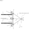
- each of the one or more guide lights 4 is enclosed within a baffle chamber 52.
- the baffle chamber 52 is defined by baffle walls 54 and has a first end 56, at which the guide light is positioned, and a second end 58, from which the light is emitted.
- the baffle chamber 52 narrows from the first end 56 to the second end 58, and in certain embodiments, forms a substantially cone-like shape.
- light is emitted from the second end 58 through a baffle chamber slit 60.
- the baffle chamber slit 60 ensures that only light that leaves the baffle chamber 52 is traveling at the proper angle to achieve alignment with the subjects eye (not shown).
- the baffle chamber walls 54 are comprised of an anti-reflective material, thus further ensuring that only light at the proper angle leaves the baffle chamber 52.
- air pockets or voids within the baffle chamber 52 are employed to further minimize reflection.
- the baffle slits 60 are angled toward the center of the optical path 57.
- the baffle chamber is a guide light assembly, a described elsewhere herein.
- baffle chambers 52 there are multiple baffle chambers 52.
- the guide lights 4 are disposed within the baffle chambers 52 and the baffle chambers 52 are mounted on a housing 64 configured to interface with an optical imaging device 6.
- the baffle chambers 52 are pivotally mounted on the housing 64, such as by way of a hinge 62.
- the angle of the baffle chamber 52, and thus the angle of the emitted guide light beam 51 is adjusted according to the desired ocular alignment point 53.
- the pivotal movement of the baffle chambers 52 around their hinges 62 is driven by an electric motor or the like so that the baffle chambers 52 can be pivoted according to predetermined angles corresponding with various desired points of alignment.
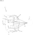
- an alignment device 63 for aligning the eye 2 of a subject with an ocular imaging device (not shown).
- the alignment device 63 comprises a housing 64 with a first end 66, a second end 68, an outer surface 70, and an inner surface 72 (as best shown in FIG. 7 ).
- the housing 64 first end 66 is configured to interface with an ocular imaging device (such as, for example, a device similar to the device 6 embodiments shown in FIGS. 1A-2B and 5 ) while the second end 68 is proximal to the eye 2 of the subject.
- an ocular imaging device such as, for example, a device similar to the device 6 embodiments shown in FIGS. 1A-2B and 5
- the second end 68 is proximal to the eye 2 of the subject.
- the housing 64 is a substantially tubular shape defining a luminal space 82 defined by its inner surface 72 through which the optical path 80 (as shown in FIG. 6 ) between the optical imaging device and the eye 2 of the subject can pass.
- a plurality of guide light assemblies 74 is arranged on the housing 64.
- the guide light assemblies 74 comprise a body 76 having a first side 84 extending from the housing outer surface 70 and a second side 86 facing the luminal space 82.
- the guide light assemblies 74 are slidably mounted into the housing 64 such that the user can adjust the position of the guide light assembly 74 along a longitudinal axis 71.
- the guide light assembly body 76 defines a channel 88 extending from the guide light assembly body first side 84 to the second side 86 as best shown via the longitudinal axis depicted schematically via line A in FIG. 8A .
- the channel forms a first opening 88a on guide light assembly body first side 84 and a second opening 88b guide light assembly body second side 86.
- Disposed within the channel 88 is a guide light bezel 73 and a guide light 77 disposed within the guide light bezel 73 (best shown in FIG. 8A ).
- FIGS. 8A As best shown in FIGS.
- the guide light bezel 73 is disposed partially within the channel 88 such that a portion of the bezel 73 extends out of the channel 88 on the first side 84.
- the guide light assembly may further comprise a power supply, housed within the body (not shown).
- the guide light assembly 74 further comprises a baffle 90 positioned in the channel 88 at or near the second channel opening 88b on the second side 86 (disposed between the guide light 77 and the second channel opening 88b).
- the baffle 90 is positioned such that it is transverse to the longitudinal axis of the channel 88.
- the baffle 90 has a slit 92 defined in the baffle 90 that is positioned longitudinally along the length of the baffle 90. In use, the baffle 90 occludes rays emitted by the guide light 77, while the slit 92 permits passage of rays traveling along the alignment path 99 (best shown in FIG. 9A ).
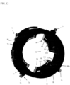
- the device further comprises a plurality of secondary baffle assemblies 96 (best shown in FIGS. 7 and 10-13 ).
- the plurality of secondary baffle assemblies 96 is arranged on the second end 68 of the housing 64 such that the baffle assemblies 96 extend inward toward the center of the luminal space 82, as best shown in FIG. 12 .
- the secondary baffle assemblies 96 are slidably mounted into the housing 64 such that the user can adjust the position of the secondary baffle assembly 96 along a longitudinal axis 71.
- each of the secondary baffle assemblies 96 further comprise a baffle plate 101 and a baffle wall 108 extending into the luminal space 82, as mentioned above.
- the baffle plate 101 further comprises a slit 98.
- light 97 emitted from the slit (not shown) in the baffle 90 is further masked by the secondary baffle assembly 96, with the baffle plate 101 and the baffle wall 108 blocking light 97 not along the alignment path.
- the slit 98 mentioned above is configured to allow passage of guide light rays 99 along the path of alignment.
- adjustment of the guide light assembly or the secondary baffle assembly 96 along the longitudinal axis 71 permits the adjustment of the angle at which the guide light rays 99 are emitted and masked. Such adjustment makes it possible to modify the alignment points with respect to the eye of the subject 2.
- the baffle slit 92 and the secondary baffle assembly 96 slit 98 have a generally perpendicular orientation with respect to one another.
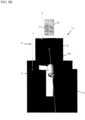
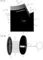
- FIG. 9D shows a schematic representation of the effect of slit orientation on light masking. As shown in that figure, rays 97 are emitted along the length of the baffle slit 92. The secondary baffle assembly 96 masks all rays 97 except for ray at the proper alignment path 99 which passes through the secondary baffle assembly slit 98 and is perceptible to the subject's eye 2, indicating proper alignment.
- the disclosed devices and systems are capable of imaging multiple ocular regions.
- proper alignment is achieved when the subject's eye is aligned for imaging of the retina.
- proper alignment is achieved when the subject's eye is aligned for imaging the cornea.
- proper alignment is achieved when the subject's eye is aligned for imaging the iris.
- proper alignment is achieved when the subject's eye is aligned for imaging the lens.
- proper alignment is achieved when the subject's eye is aligned for imaging the optic nerve head.
- the disclosed systems and devices can be used with numerous optical imaging systems.
- the optical imaging device is a fundus camera.
- the camera is an optical coherence tomography (OCT) retinal camera.
- OCT optical coherence tomography
- the optical imaging device is an autorefractor.
- the optical imaging device is a corneal camera.
- OCT optical coherence tomography
- other camera types are possible.
- the system further comprises one or more indicator signals.
- each indicator signal serves to provide additional guidance to the subject regarding the required direction of eye movement to achieve alignment.
- Example indicator signals include, but are not limited to, arrows, colors, or flashing lights.
- sounds and/or other non-visual feedback cues are also possible.
- the indicator signals are masked by one or more baffles such that they are only visible when the eye is out of alignment. For example, a rightward pointing arrow indicator signal is baffled such that it is only visible to the subject when the subject eye is directed to the left of proper alignment.
- indicator signals are comprised of colored ring lights of differing colors (not shown).
- the one or more guide lights is a color different from the colors of the one or more indicator signal.
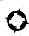
- FIG. 14A shows an eye of a subject 2 out of alignment where the subject is able to view a red indicator signal light 102 but unable to see the green guide light 106.
- FIG.14B shows an eye of a subject in proper alignment where the subject is able to see the green guide light 106 but unable to see the yellow 104 or red indicator signals 106.
- the indicator signal the subject is able to view conveys information to the subject about the direction the eye needs to adjust in order to achieve proper alignment.
- a device for aligning a subject's eye with an optical axis of an ocular imaging device comprising a housing, the housing comprising a first end, a second end, an outer surface, and an inner surface, wherein the inner surface defines a luminal space and wherein the luminal space is configured to allow for passage of the optical axis therethrough; a plurality of guide light assemblies disposed within the housing, each guide light assembly comprising a body, the body comprising a first side and a second side opposite the first side, wherein the second side faces the luminal space a channel defined in the body, wherein the channel extends from the body first side to the body second side, wherein the channel forms an opening in the body second side; a guide light disposed within the channel, wherein the guide light is configured to emit rays out of the opening; and a baffle disposed transversely in the channel between the guide light and the opening and configured to mask rays from the guide light, wherein the baffle further comprises a slit configured
- the plurality of guide light assemblies are slideably mounted to the housing.
- the plurality of secondary baffle assemblies are slidably mounted to the housing.
- the secondary baffle assemblies each further comprise a baffle plate, wherein the slit is positioned on the baffle plate, and a baffle wall. the baffle wall extends into the luminal space of the housing toward the housing first end.
- at least one of the plurality of secondary baffle assemblies is comprised of anti-reflective material.
- the disclosed device further comprises a co-axial light, visible to the subject when the subject's is in coarse alignment.
- the disclosed device further comprises a first set of the plurality of guide lights wherein the first set of guide lights is visible to the subject when the optical axis of the subject's eye is in alignment along a x-axis with respect to the optical axis of the ocular device; and a second set of guide lights, visible to the subject when the optical axis of the subject's eye is in alignment along a y-axis with respect to the optical axis of the ocular device, wherein when the first set of guide lights and second set of guide lights are simultaneously visible to the subject, the subject's eye is in alignment with the z-axis.
- an ocular alignment system for aligning the optical axis of a subject's eye with an optical axis of an ocular imaging device comprising a plurality of guide lights; and one or more baffle configured to mask the one or more guide light from view of the subject such that the one or more guide light is only visible to the subject when the optical axis of the subject's eye is aligned with the optical axis of an ocular imaging system.
- At least one of the plurality of guide light is a ring light.
- a set of the plurality of the plurality of guide lights is perceptible to the subject as varying spatial patterns indicating the direction of eye movement required for alignment.
- each of the plurality of guide lights is comprised of a distinct light source.
- the disclosed system further comprises one or more sets of guide lights wherein one or more guide lights or regions of guide lights are turned on or off in different patterns for different optical fixation points.
- one or more baffle is a cone.
- the one or more baffle further comprises one or more slits, configured to allow passage of rays along the alignment path.
- the one or more baffles further comprises an air cavity or light absorption materials in combination or separately to minimize guide light reflection.
- the plurality of baffles or guide lights are adjustable to control a z-axes focal point to the subject's eye.
- the disclosed system further comprising a first set of the plurality of guide lights wherein the first set of guide lights is visible to the subject when the subject's eye is in alignment along a x-axis with respect to the optical axis; and a second set of guide lights, visible to the subject when the subject's eye is in alignment along a y-axis with respect to the optical axis, wherein when the first set of guide lights and second set of guide lights are simultaneously visible to the subject, the subject's eye is in alignment with the z-axis.
- a set of the plurality of guide light is only visible when the eye is aligned along the x, y and z axes with respect to the optical path of the ocular imaging device.
- the one or more guide light sources is positioned in the x-y plane at varying z-distance to optimize guide light path(s) to the subject.
- the one or more guide light is only visible when the eye is aligned along the ⁇ , ⁇ , and ⁇ axes with respect to the optical path of the ocular imaging device.
- the disclosed system further comprises one or more indicator signals, wherein the one or more indicator signals indicates to the subject a direction of eye movement to achieve alignment.
- the disclosed system further comprises one or more baffles to mask the one or more indicator signals from view of the subject such that the one or more indicator signal is only visible to the subject when the optical axis of the eye of the subject is out of alignment with the optical axis or a target operational distance of the ocular imaging system.
- one or more indicator signals are arrows.
- the one or more indicator signals are colored lights.
- the disclosed ocular alignment system is integrated within optical imaging device. In further aspects, the ocular alignment system is external to the optical imaging device.
- the disclosed system further comprises a coaxial light, visible to the subject when coarse alignment is achieved.
- a method of aligning a subject's eye with an optical axis of an ocular imaging device comprising providing a first set of guide lights along the optical path between the subject's eye and the ocular imaging device and providing one or more baffle, configured to mask the first set of guide lights from view of the subject such that first set of guide lights is only visible to the subject when the optical axis of the subject's eye is aligned with the optical axis of an ocular imaging system.
- the first set of guide lights is visible to the subject when the optical axis of the subject's eye is in alignment along a x-axis with respect to the optical axis of the ocular imaging device
- the method further comprises providing a second set of guide lights, visible to the subject when optical axis of the subject's eye is in alignment along a y-axis with respect to the optical axis of the ocular imaging device; and wherein when the first set of guide lights and second set of guide lights are simultaneously visible to the subject, the subject's eye is in alignment with the z-axis.
- the disclosed method further comprises providing a set of indicator lights visible to the subject when the subject's eye is out of alignment.
- the indicator signals are comprised of no-visual signals, including but not limited to auditory and tactile indicator signals.
- the disclosed method further comprises providing a sequence of guide lights, wherein each guide light in the sequence brings the subject's eye closer to alignment along the z-axis with respect to the optical axis of the ocular imaging system.
Landscapes
- Life Sciences & Earth Sciences (AREA)
- Health & Medical Sciences (AREA)
- Medical Informatics (AREA)
- Biophysics (AREA)
- Ophthalmology & Optometry (AREA)
- Engineering & Computer Science (AREA)
- Biomedical Technology (AREA)
- Heart & Thoracic Surgery (AREA)
- Physics & Mathematics (AREA)
- Molecular Biology (AREA)
- Surgery (AREA)
- Animal Behavior & Ethology (AREA)
- General Health & Medical Sciences (AREA)
- Public Health (AREA)
- Veterinary Medicine (AREA)
- Eye Examination Apparatus (AREA)
Applications Claiming Priority (3)
| Application Number | Priority Date | Filing Date | Title |
|---|---|---|---|
| US201462020252P | 2014-07-02 | 2014-07-02 | |
| PCT/US2015/039105 WO2016004385A1 (fr) | 2014-07-02 | 2015-07-02 | Systèmes et méthodes d'alignement de l'œil en imagerie oculaire |
| EP15815192.8A EP3164058B1 (fr) | 2014-07-02 | 2015-07-02 | Systèmes et méthodes d'alignement de l' il en imagerie oculaire |
Related Parent Applications (2)
| Application Number | Title | Priority Date | Filing Date |
|---|---|---|---|
| EP15815192.8A Division-Into EP3164058B1 (fr) | 2014-07-02 | 2015-07-02 | Systèmes et méthodes d'alignement de l' il en imagerie oculaire |
| EP15815192.8A Division EP3164058B1 (fr) | 2014-07-02 | 2015-07-02 | Systèmes et méthodes d'alignement de l' il en imagerie oculaire |
Publications (2)
| Publication Number | Publication Date |
|---|---|
| EP4501209A2 true EP4501209A2 (fr) | 2025-02-05 |
| EP4501209A3 EP4501209A3 (fr) | 2025-04-02 |
Family
ID=55020026
Family Applications (2)
| Application Number | Title | Priority Date | Filing Date |
|---|---|---|---|
| EP24215245.2A Pending EP4501209A3 (fr) | 2014-07-02 | 2015-07-02 | Systèmes et procédés d'alignement de l' il pour imagerie oculaire |
| EP15815192.8A Active EP3164058B1 (fr) | 2014-07-02 | 2015-07-02 | Systèmes et méthodes d'alignement de l' il en imagerie oculaire |
Family Applications After (1)
| Application Number | Title | Priority Date | Filing Date |
|---|---|---|---|
| EP15815192.8A Active EP3164058B1 (fr) | 2014-07-02 | 2015-07-02 | Systèmes et méthodes d'alignement de l' il en imagerie oculaire |
Country Status (4)
| Country | Link |
|---|---|
| US (4) | US9814386B2 (fr) |
| EP (2) | EP4501209A3 (fr) |
| JP (1) | JP6905463B2 (fr) |
| WO (1) | WO2016004385A1 (fr) |
Families Citing this family (15)
| Publication number | Priority date | Publication date | Assignee | Title |
|---|---|---|---|---|
| US9662014B2 (en) | 2015-04-17 | 2017-05-30 | Massachusetts Institute Of Technology | Methods and apparatus for visual cues for eye alignment |
| CN111511268B (zh) | 2017-11-07 | 2023-12-26 | 诺达尔视觉有限公司 | 视网膜成像设备和相关方法 |
| WO2019092696A1 (fr) | 2017-11-07 | 2019-05-16 | Notal Vision Ltd. | Procédés et systèmes d'alignement de dispositifs d'imagerie ophtalmique |
| FI129683B (en) * | 2018-09-11 | 2022-06-30 | Icare Finland Oy | Alignment device for measuring instruments |
| US10595722B1 (en) | 2018-10-03 | 2020-03-24 | Notal Vision Ltd. | Automatic optical path adjustment in home OCT |
| WO2020112996A1 (fr) * | 2018-11-28 | 2020-06-04 | Broadspot Imaging Corp | Système d'imagerie de champ ultra-large du segment postérieur |
| US10653311B1 (en) | 2019-06-12 | 2020-05-19 | Notal Vision Ltd. | Home OCT with automatic focus adjustment |
| US20220338733A1 (en) * | 2019-10-29 | 2022-10-27 | Verily Life Sciences Llc | External alignment indication/guidance system for retinal camera |
| EP4204890B1 (fr) * | 2020-07-27 | 2025-10-29 | Apple Inc. | Dispositifs électroniques ayant des rails de guidage sollicités |
| US12171496B2 (en) | 2020-08-19 | 2024-12-24 | Digital Diagnostics Inc. | Using infrared to detect proper eye alignment before capturing retinal images |
| GB202013062D0 (en) * | 2020-08-21 | 2020-10-07 | Oivi As | Apparatus and method for ophthalmic imaging |
| FI131536B1 (en) * | 2020-12-21 | 2025-06-16 | Optomed Oyj | Eye examination device and eye examination procedure |
| CN113197555A (zh) * | 2021-06-04 | 2021-08-03 | 哈尔滨医科大学 | 多方向oct图像采集导管 |
| WO2024238546A1 (fr) * | 2023-05-15 | 2024-11-21 | Massachusetts Institute Of Technology | Dispositif d'assistance pour les gouttes oculaires et procédé d'utilisation |
| CN116636809B (zh) * | 2023-05-29 | 2024-09-17 | 微智医疗器械有限公司 | 对准装置和回弹式眼压计 |
Family Cites Families (37)
| Publication number | Priority date | Publication date | Assignee | Title |
|---|---|---|---|---|
| JPS6266833A (ja) * | 1985-09-19 | 1987-03-26 | ト−メ−産業株式会社 | 角膜の定位置誘導装置および定位置誘導方法 |
| JPH03176023A (ja) * | 1989-12-04 | 1991-07-31 | Canon Inc | 眼科装置 |
| JP3285936B2 (ja) * | 1992-07-03 | 2002-05-27 | 株式会社トプコン | 眼科装置 |
| JPH06114006A (ja) * | 1992-10-02 | 1994-04-26 | Canon Inc | 検査装置 |
| US5442412A (en) | 1994-04-25 | 1995-08-15 | Autonomous Technologies Corp. | Patient responsive eye fixation target method and system |
| US5822036A (en) | 1996-07-24 | 1998-10-13 | Research Development Foundation | Eye imaging unit having a circular light guide |
| US5777719A (en) | 1996-12-23 | 1998-07-07 | University Of Rochester | Method and apparatus for improving vision and the resolution of retinal images |
| US6361495B1 (en) | 2000-02-07 | 2002-03-26 | Leica Microsystems Inc. | Hand-held non-contact tonometer |
| JP3401502B2 (ja) | 2000-07-13 | 2003-04-28 | 松下電器産業株式会社 | 目画像撮像装置 |
| US6554428B2 (en) | 2000-09-07 | 2003-04-29 | I-O Display Systems Llc | Method and apparatus for adjusting optical device to correspond to eye positions |
| US6486943B1 (en) * | 2000-09-19 | 2002-11-26 | The Schepens Eye Research Institute, Inc. | Methods and apparatus for measurement and correction of optical aberration |
| WO2003025838A1 (fr) * | 2001-09-14 | 2003-03-27 | The Arizona Board Of Regents On Behalf Of The University Of Arizona | Systeme d'ecran entre objectifs |
| US6873714B2 (en) | 2002-02-19 | 2005-03-29 | Delphi Technologies, Inc. | Auto calibration and personalization of eye tracking system using larger field of view imager with higher resolution |
| JP4018425B2 (ja) | 2002-03-29 | 2007-12-05 | 松下電器産業株式会社 | 目画像撮像装置 |
| US20050046794A1 (en) * | 2003-06-17 | 2005-03-03 | Silvestrini Thomas A. | Method and apparatus for aligning a mask with the visual axis of an eye |
| JP4865257B2 (ja) | 2004-09-29 | 2012-02-01 | キヤノン株式会社 | 眼底撮影装置及びプログラム |
| EP2010041A2 (fr) | 2006-04-11 | 2009-01-07 | Neuroptix Corporation | Imagerie oculaire |
| US7758189B2 (en) | 2006-04-24 | 2010-07-20 | Physical Sciences, Inc. | Stabilized retinal imaging with adaptive optics |
| US7620147B2 (en) | 2006-12-13 | 2009-11-17 | Oraya Therapeutics, Inc. | Orthovoltage radiotherapy |
| US8363783B2 (en) * | 2007-06-04 | 2013-01-29 | Oraya Therapeutics, Inc. | Method and device for ocular alignment and coupling of ocular structures |
| US8718335B2 (en) | 2007-11-29 | 2014-05-06 | Wavefront Biometric Technologies Pty Limited | Biometric authentication using the eye |
| JP2010200905A (ja) * | 2009-03-02 | 2010-09-16 | Nidek Co Ltd | 眼科装置 |
| US9642520B2 (en) * | 2009-04-01 | 2017-05-09 | Tearscience, Inc. | Background reduction apparatuses and methods of ocular surface interferometry (OSI) employing polarization for imaging, processing, and/or displaying an ocular tear film |
| BRPI1014853A2 (pt) * | 2009-04-01 | 2015-08-25 | Tearscience Inc | Dispositivos, sistemas e métodos de interferometria de superfície ocular (osi) para formação de imagem, processamento e/ou visualização de um filme lacrimal ocular e/ou medição de espessura(s) de camada de filme lacrimal ocular |
| JP4995244B2 (ja) | 2009-08-27 | 2012-08-08 | キヤノン株式会社 | 眼科撮影装置 |
| US20130057828A1 (en) * | 2009-08-31 | 2013-03-07 | Marc De Smet | Handheld portable fundus imaging system and method |
| WO2011038457A1 (fr) * | 2009-09-30 | 2011-04-07 | Lions Eye Institute Limited | Imageur, module pour imageur, système d'imagerie et procédé associé |
| WO2011047214A2 (fr) | 2009-10-14 | 2011-04-21 | Optimum Technologies, Inc. | Caméra rétinienne portative et procédé d'acquisition d'images |
| WO2011091253A2 (fr) | 2010-01-21 | 2011-07-28 | Physical Sciences, Inc. | Imagerie rétinale par optique adaptative multifonctionnelle |
| WO2011116306A2 (fr) | 2010-03-19 | 2011-09-22 | Avedro, Inc. | Systèmes et méthodes d'application et de surveillance de thérapie oculaire |
| GB2485175A (en) | 2010-11-03 | 2012-05-09 | Univ City | Optical imaging system using incoherent light and interference fringes |
| US9398851B2 (en) | 2011-06-24 | 2016-07-26 | Remidio Innovative Solutions Pvt. Ltd. | Retinal imaging device |
| US8596788B2 (en) | 2011-06-27 | 2013-12-03 | Broadspot Imaging Corporation | Multiple-view composite ophthalmic iridocorneal angle imaging system |
| WO2013049248A2 (fr) * | 2011-09-26 | 2013-04-04 | Osterhout Group, Inc. | Modification d'affichage vidéo sur la base d'une entrée de capteur pour dispositif d'affichage près de l'œil semi-transparent |
| WO2013086075A1 (fr) | 2011-12-08 | 2013-06-13 | Volk Optical, Inc. | Dispositif d'imagerie de la rétine comprenant un capteur de poursuite optique sensible à la position |
| JP5887191B2 (ja) | 2012-04-19 | 2016-03-16 | 株式会社トーメーコーポレーション | 角膜撮影装置および角膜撮影方法 |
| WO2013163383A1 (fr) * | 2012-04-25 | 2013-10-31 | Tearscience, Inc. | Appareil et procédé de réduction de fond d'une interférométrie de surface oculaire (osi) utilisant la polarisation pour l'imagerie, le traitement et/ou l'affichage d'un film lacrymal oculaire |
-
2015
- 2015-07-02 EP EP24215245.2A patent/EP4501209A3/fr active Pending
- 2015-07-02 WO PCT/US2015/039105 patent/WO2016004385A1/fr not_active Ceased
- 2015-07-02 US US14/791,028 patent/US9814386B2/en active Active
- 2015-07-02 JP JP2017500041A patent/JP6905463B2/ja active Active
- 2015-07-02 EP EP15815192.8A patent/EP3164058B1/fr active Active
-
2017
- 2017-11-14 US US15/812,596 patent/US10694945B2/en active Active
-
2020
- 2020-06-30 US US16/917,504 patent/US11903649B2/en active Active
-
2023
- 2023-12-20 US US18/391,406 patent/US20240122475A1/en active Pending
Also Published As
| Publication number | Publication date |
|---|---|
| US20240122475A1 (en) | 2024-04-18 |
| EP3164058A4 (fr) | 2018-03-07 |
| JP2017520328A (ja) | 2017-07-27 |
| EP3164058B1 (fr) | 2025-01-08 |
| EP3164058C0 (fr) | 2025-01-08 |
| US20160183788A1 (en) | 2016-06-30 |
| US10694945B2 (en) | 2020-06-30 |
| EP4501209A3 (fr) | 2025-04-02 |
| US11903649B2 (en) | 2024-02-20 |
| US20180064337A1 (en) | 2018-03-08 |
| EP3164058A1 (fr) | 2017-05-10 |
| US9814386B2 (en) | 2017-11-14 |
| WO2016004385A1 (fr) | 2016-01-07 |
| JP6905463B2 (ja) | 2021-07-21 |
| US20200329963A1 (en) | 2020-10-22 |
Similar Documents
| Publication | Publication Date | Title |
|---|---|---|
| US20240122475A1 (en) | Systems and methods for alignment of the eye for ocular imaging | |
| EP3157481B1 (fr) | Dispositif laser diagnostique et chirurgical utilisant une diode laser visible | |
| EP3517018A1 (fr) | Système endoscopique pour visualisation optimisée | |
| JP6812724B2 (ja) | 眼科手術システム、眼科手術システム制御プログラム、および眼科用手術顕微鏡 | |
| JP6503647B2 (ja) | レーザ治療装置 | |
| JPH10328226A (ja) | レーザ治療装置 | |
| EP3086744B1 (fr) | Système et dispositif de photocoagulation multispot | |
| US11266528B2 (en) | Treatment laser with reflex mirror and safety interlock | |
| EP3849397B1 (fr) | Moyen d'alignement d'un instrument de mesure | |
| KR101765491B1 (ko) | 부작용을 예방하고 치료 효과를 높일 수 있는 레이저 치료용 핸드피스 장치 | |
| EP3214994B1 (fr) | Système de lentilles pour l'inspection d'un oeil | |
| US20230414412A1 (en) | Apparatus for Ophthalmic Treatment | |
| US20160242643A1 (en) | Transparent Camera for Imaging the Eye | |
| US7810927B2 (en) | Refractive treatment device with slit illumination | |
| US20240099887A1 (en) | System and method for laser treatment of ocular tissue based on pigmentation | |
| US20240058170A1 (en) | Systems and methods for treating glaucoma with laser pulses and visualizing the anterior angle of the eye | |
| US12193743B2 (en) | Ophthalmic apparatus | |
| KR20200015312A (ko) | 드론을 이용한 수술등 시스템 및 그 이용방법 | |
| WO2026061792A1 (fr) | Système d'ophtalmoscope indirect laser (oil) multi-spots pouvant être monté sur le corps | |
| HK40044454A (en) | Alignment means of measurement instrument | |
| KR20210009196A (ko) | 안과용 영상 촬영 장치 | |
| JP2008073385A (ja) | 眼球運動の視軸照射軸同軸化追尾装置の作動方法 |
Legal Events
| Date | Code | Title | Description |
|---|---|---|---|
| PUAI | Public reference made under article 153(3) epc to a published international application that has entered the european phase |
Free format text: ORIGINAL CODE: 0009012 |
|
| STAA | Information on the status of an ep patent application or granted ep patent |
Free format text: STATUS: THE APPLICATION HAS BEEN PUBLISHED |
|
| AC | Divisional application: reference to earlier application |
Ref document number: 3164058 Country of ref document: EP Kind code of ref document: P |
|
| AK | Designated contracting states |
Kind code of ref document: A2 Designated state(s): AL AT BE BG CH CY CZ DE DK EE ES FI FR GB GR HR HU IE IS IT LI LT LU LV MC MK MT NL NO PL PT RO RS SE SI SK SM TR |
|
| REG | Reference to a national code |
Ref country code: DE Ref legal event code: R079 Free format text: PREVIOUS MAIN CLASS: A61B0003000000 Ipc: A61B0003150000 |
|
| PUAL | Search report despatched |
Free format text: ORIGINAL CODE: 0009013 |
|
| AK | Designated contracting states |
Kind code of ref document: A3 Designated state(s): AL AT BE BG CH CY CZ DE DK EE ES FI FR GB GR HR HU IE IS IT LI LT LU LV MC MK MT NL NO PL PT RO RS SE SI SK SM TR |
|
| RIC1 | Information provided on ipc code assigned before grant |
Ipc: A61B 3/00 20060101ALI20250224BHEP Ipc: A61B 3/15 20060101AFI20250224BHEP |
|
| STAA | Information on the status of an ep patent application or granted ep patent |
Free format text: STATUS: REQUEST FOR EXAMINATION WAS MADE |
|
| 17P | Request for examination filed |
Effective date: 20250925 |
|
| GRAP | Despatch of communication of intention to grant a patent |
Free format text: ORIGINAL CODE: EPIDOSNIGR1 |
|
| STAA | Information on the status of an ep patent application or granted ep patent |
Free format text: STATUS: GRANT OF PATENT IS INTENDED |
|
| INTG | Intention to grant announced |
Effective date: 20260331 |