EP4501236A1 - Implantierbare dehnbare flexible neurale elektrode, elektrodengruppe und elektrodenanordnung - Google Patents
Implantierbare dehnbare flexible neurale elektrode, elektrodengruppe und elektrodenanordnung Download PDFInfo
- Publication number
- EP4501236A1 EP4501236A1 EP23778417.8A EP23778417A EP4501236A1 EP 4501236 A1 EP4501236 A1 EP 4501236A1 EP 23778417 A EP23778417 A EP 23778417A EP 4501236 A1 EP4501236 A1 EP 4501236A1
- Authority
- EP
- European Patent Office
- Prior art keywords
- electrode
- implantable
- flexible neural
- flexible
- stretchable
- Prior art date
- Legal status (The legal status is an assumption and is not a legal conclusion. Google has not performed a legal analysis and makes no representation as to the accuracy of the status listed.)
- Pending
Links
Images









Classifications
-
- A—HUMAN NECESSITIES
- A61—MEDICAL OR VETERINARY SCIENCE; HYGIENE
- A61B—DIAGNOSIS; SURGERY; IDENTIFICATION
- A61B5/00—Measuring for diagnostic purposes; Identification of persons
- A61B5/24—Detecting, measuring or recording bioelectric or biomagnetic signals of the body or parts thereof
- A61B5/25—Bioelectric electrodes therefor
- A61B5/279—Bioelectric electrodes therefor specially adapted for particular uses
- A61B5/291—Bioelectric electrodes therefor specially adapted for particular uses for electroencephalography [EEG]
-
- A—HUMAN NECESSITIES
- A61—MEDICAL OR VETERINARY SCIENCE; HYGIENE
- A61B—DIAGNOSIS; SURGERY; IDENTIFICATION
- A61B5/00—Measuring for diagnostic purposes; Identification of persons
- A61B5/24—Detecting, measuring or recording bioelectric or biomagnetic signals of the body or parts thereof
-
- A—HUMAN NECESSITIES
- A61—MEDICAL OR VETERINARY SCIENCE; HYGIENE
- A61B—DIAGNOSIS; SURGERY; IDENTIFICATION
- A61B5/00—Measuring for diagnostic purposes; Identification of persons
- A61B5/24—Detecting, measuring or recording bioelectric or biomagnetic signals of the body or parts thereof
- A61B5/25—Bioelectric electrodes therefor
- A61B5/279—Bioelectric electrodes therefor specially adapted for particular uses
- A61B5/291—Bioelectric electrodes therefor specially adapted for particular uses for electroencephalography [EEG]
- A61B5/293—Invasive
-
- A—HUMAN NECESSITIES
- A61—MEDICAL OR VETERINARY SCIENCE; HYGIENE
- A61B—DIAGNOSIS; SURGERY; IDENTIFICATION
- A61B5/00—Measuring for diagnostic purposes; Identification of persons
- A61B5/24—Detecting, measuring or recording bioelectric or biomagnetic signals of the body or parts thereof
- A61B5/25—Bioelectric electrodes therefor
- A61B5/279—Bioelectric electrodes therefor specially adapted for particular uses
- A61B5/294—Bioelectric electrodes therefor specially adapted for particular uses for nerve conduction study [NCS]
-
- A—HUMAN NECESSITIES
- A61—MEDICAL OR VETERINARY SCIENCE; HYGIENE
- A61B—DIAGNOSIS; SURGERY; IDENTIFICATION
- A61B5/00—Measuring for diagnostic purposes; Identification of persons
- A61B5/24—Detecting, measuring or recording bioelectric or biomagnetic signals of the body or parts thereof
- A61B5/30—Input circuits therefor
- A61B5/307—Input circuits therefor specially adapted for particular uses
- A61B5/31—Input circuits therefor specially adapted for particular uses for electroencephalography [EEG]
-
- A—HUMAN NECESSITIES
- A61—MEDICAL OR VETERINARY SCIENCE; HYGIENE
- A61B—DIAGNOSIS; SURGERY; IDENTIFICATION
- A61B5/00—Measuring for diagnostic purposes; Identification of persons
- A61B5/24—Detecting, measuring or recording bioelectric or biomagnetic signals of the body or parts thereof
- A61B5/316—Modalities, i.e. specific diagnostic methods
- A61B5/369—Electroencephalography [EEG]
- A61B5/37—Intracranial electroencephalography [IC-EEG], e.g. electrocorticography [ECoG]
-
- A—HUMAN NECESSITIES
- A61—MEDICAL OR VETERINARY SCIENCE; HYGIENE
- A61N—ELECTROTHERAPY; MAGNETOTHERAPY; RADIATION THERAPY; ULTRASOUND THERAPY
- A61N1/00—Electrotherapy; Circuits therefor
- A61N1/02—Details
- A61N1/04—Electrodes
- A61N1/05—Electrodes for implantation or insertion into the body, e.g. heart electrode
- A61N1/0526—Head electrodes
- A61N1/0529—Electrodes for brain stimulation
-
- A—HUMAN NECESSITIES
- A61—MEDICAL OR VETERINARY SCIENCE; HYGIENE
- A61N—ELECTROTHERAPY; MAGNETOTHERAPY; RADIATION THERAPY; ULTRASOUND THERAPY
- A61N1/00—Electrotherapy; Circuits therefor
- A61N1/02—Details
- A61N1/04—Electrodes
- A61N1/05—Electrodes for implantation or insertion into the body, e.g. heart electrode
- A61N1/0526—Head electrodes
- A61N1/0529—Electrodes for brain stimulation
- A61N1/0534—Electrodes for deep brain stimulation
-
- A—HUMAN NECESSITIES
- A61—MEDICAL OR VETERINARY SCIENCE; HYGIENE
- A61N—ELECTROTHERAPY; MAGNETOTHERAPY; RADIATION THERAPY; ULTRASOUND THERAPY
- A61N1/00—Electrotherapy; Circuits therefor
- A61N1/02—Details
- A61N1/04—Electrodes
- A61N1/05—Electrodes for implantation or insertion into the body, e.g. heart electrode
- A61N1/0526—Head electrodes
- A61N1/0529—Electrodes for brain stimulation
- A61N1/0539—Anchoring of brain electrode systems, e.g. within burr hole
-
- A—HUMAN NECESSITIES
- A61—MEDICAL OR VETERINARY SCIENCE; HYGIENE
- A61N—ELECTROTHERAPY; MAGNETOTHERAPY; RADIATION THERAPY; ULTRASOUND THERAPY
- A61N1/00—Electrotherapy; Circuits therefor
- A61N1/02—Details
- A61N1/04—Electrodes
- A61N1/05—Electrodes for implantation or insertion into the body, e.g. heart electrode
- A61N1/0551—Spinal or peripheral nerve electrodes
-
- A—HUMAN NECESSITIES
- A61—MEDICAL OR VETERINARY SCIENCE; HYGIENE
- A61N—ELECTROTHERAPY; MAGNETOTHERAPY; RADIATION THERAPY; ULTRASOUND THERAPY
- A61N1/00—Electrotherapy; Circuits therefor
- A61N1/02—Details
- A61N1/04—Electrodes
- A61N1/05—Electrodes for implantation or insertion into the body, e.g. heart electrode
- A61N1/0551—Spinal or peripheral nerve electrodes
- A61N1/0556—Cuff electrodes
-
- A—HUMAN NECESSITIES
- A61—MEDICAL OR VETERINARY SCIENCE; HYGIENE
- A61N—ELECTROTHERAPY; MAGNETOTHERAPY; RADIATION THERAPY; ULTRASOUND THERAPY
- A61N1/00—Electrotherapy; Circuits therefor
- A61N1/02—Details
- A61N1/04—Electrodes
- A61N1/05—Electrodes for implantation or insertion into the body, e.g. heart electrode
- A61N1/0551—Spinal or peripheral nerve electrodes
- A61N1/0558—Anchoring or fixation means therefor
-
- A—HUMAN NECESSITIES
- A61—MEDICAL OR VETERINARY SCIENCE; HYGIENE
- A61B—DIAGNOSIS; SURGERY; IDENTIFICATION
- A61B2562/00—Details of sensors; Constructional details of sensor housings or probes; Accessories for sensors
- A61B2562/12—Manufacturing methods specially adapted for producing sensors for in-vivo measurements
- A61B2562/125—Manufacturing methods specially adapted for producing sensors for in-vivo measurements characterised by the manufacture of electrodes
Definitions
- At least one embodiment of the present disclosure relates to an implantable stretchable flexible neural electrode, an implantable stretchable flexible neural electrode group, an implantable stretchable flexible neural electrode array, as well as a manufacturing method and an implantation method thereof.
- the main function of neural electrode is to realize mutual conversion between bioelectrical signals with ions as carriers and universal electrical signals with electrons as carriers, so as to realize the recording and regulation of brain signals and peripheral nerve signals.
- the existing neural electrodes include electroencephalogram (EEG) electrodes, electrocorticography (ECoG) electrodes and implantable electrodes.
- EEG electroencephalogram
- EoG electrocorticography
- Implantable neural electrodes can record and regulate the electrical activities of multiple neurons, and hence have a broad application prospect in the fields of nervous system disease treatment and brain-computer interface, etc.
- the most widely used implantable neural electrode is silicon-based rigid neural electrode.
- the mechanical properties of rigid neural electrodes do not match the brain, causing great mechanical damage.
- the rigid electrode is easy to move slightly in the brain, which leads to the instability of neural signal recording and aggravates the inflammatory reaction of the brain.
- colloid cells are generated around the electrode and attached onto the surface of the electrode site, leading to the attenuation of electrical signals and the failure of the electrode site. Therefore, it is difficult for rigid electrodes to ensure the long-term stability of signal recording.
- the mechanical properties of the flexible neural electrode match the large target tissue, which greatly reduces the movement with the target tissue and the inflammatory reaction of the target tissue, thus realizing long-term stable recording and regulation of nerve signals.
- the structure of flexible neural electrode is mostly based on linear electrode wire structure, which limits the high-throughput transfer and in-situ implantation of electrode wire. Moreover, the implantation depth of flexible linear electrode wire is limited by the size of processing technology and the movable distance of the electrode.
- an implantable stretchable flexible neural electrode including an electrode wire and a flexible insulating part wrapping the electrode wire, wherein the flexible neural electrode includes a spiral structure of the electrode wire and the flexible insulating part, wherein the spiral structure is stretchable; an electrode site and an auxiliary implantation structure are provided at the spiral structure; the electrode site is electrically connected to the electrode wire and exposed from the flexible insulating part; and the auxiliary implantation structure is configured to drive the spiral structure to stretch under an action of external force.
- the spiral structure is configured to be stretchable in any direction.
- the spiral structure includes a plurality of circles, wherein any two adjacent circles among the plurality of circles are an inner circle and an outer circle, respectively, the outer circle surrounds the inner circle, and a termination end of the outer circle is connected to an initial end of the inner circle.
- the auxiliary implantation structure is provided at an innermost circle among the plurality of circles.
- the flexible insulating part is provided with a protruding part extending beyond the electrode wire, and the auxiliary implantation structure is a through hole, a groove or a protrusion provided at the protruding part.
- a position mark is provided on the protruding part.
- each of the plurality of circles includes a plurality of curved portions connected in sequence.
- the implantable stretchable flexible neural electrode according to the embodiment of the present disclosure further includes a linear structure of the electrode wire and the flexible insulating part, wherein the linear structure is connected to the spiral structure.
- the linear structure includes an auxiliary electrode wire wrapped by the flexible insulating part; and in the linear structure, the auxiliary electrode wire is electrically connected to the electrode wire.
- the implantable stretchable flexible neural electrode according to the embodiment of the present disclosure further includes an anchoring structure, wherein an angle is provided between the anchoring structure and the electrode wire, and the anchoring structure is configured to interact with a target tissue after the flexible neural electrode is implanted into the target tissue so as to prevent the flexible neural electrode from moving relative to the target tissue.
- an edge of the anchoring structure extending from the electrode wire in a direction away from the electrode wire is in an arc shape, and the arc shape protrudes towards the auxiliary implantation structure.
- the anchoring structure includes an anchoring electrode wire covered by the flexible insulating part, and the electrode site is electrically connected to the electrode wire through the anchoring electrode wire.
- a material of the electrode wire and a material of the electrode site include at least one of gold, platinum and iridium; and a material of the flexible insulating part includes at least one of polyimide, parylene and SU-8 photoresist.
- the implantable stretchable flexible neural electrode according to the embodiment of the present disclosure further includes an adhesive layer provided between the electrode wire and the flexible insulating part.
- the implantable stretchable flexible neural electrode includes a plurality of electrode wires wrapped by the flexible insulating part and insulated from each other; and a plurality of electrode sites exposed from the flexible insulating part, electrically connected to the plurality of the electrode wires in one-to-one correspondence, and spatially separated from each other.
- the plurality of electrode wires are located at a same layer; or the plurality of electrode wires are located at a plurality of layers arranged in a stacked manner, and each of the plurality of layers includes at least one of the plurality of electrode wires.
- any two adjacent layers among the plurality of layers are a first layer and a second layer; in a stacking direction of the plurality of layers, the electrode wire located at the first layer and the electrode wire located at the second layer at least partially overlap or at least partially do not overlap.
- the plurality of electrode sites are located at a same side or at different sides of the flexible neural electrode.
- an implantable stretchable flexible neural electrode group including a plurality of flexible neural electrodes as described above, wherein the plurality of flexible neural electrodes are insulated from each other; a plurality of spiral structures of the plurality of flexible neural electrodes forms a composite spiral structure; and in a same circle of the composite spiral structure, parts of the plurality of spiral structures located in the same circle of the composite spiral structure are sequentially arranged from inside to outside.
- a plurality of electrode sites of the plurality of flexible neural electrodes are spatially separated from each other.
- the composite spiral structure includes a plurality of circles, wherein any two adjacent circles among the plurality of circles are an inner circle and an outer circle, respectively, the outer circle surrounds the inner circle, and a termination end of the outer circle is connected to an initial end of the inner circle; in each of the plurality of circles of the composite spiral structure, corresponding parts of the plurality of spiral structures are sequentially arranged from inside to outside in a same order.
- a plurality of auxiliary implantation structures of the plurality of flexible neural electrodes are integrated into a common auxiliary structure, and the common auxiliary structure is configured to drive a plurality of spiral structures of the plurality of flexible neural electrodes to stretch synchronously under an action of external force.
- a plurality of flexible insulating parts of the plurality of flexible neural electrodes are at least partially connected to each other.
- a plurality of auxiliary implantation structures of the plurality of flexible neural electrodes are spatially separated from each other.
- an implantable stretchable flexible neural electrode array including a plurality of flexible neural electrodes as described above, wherein the plurality of flexible neural electrodes are insulated from each other, and a plurality of spiral structures of the plurality of flexible neural electrodes are arranged in an array.
- each of the plurality of flexible neural electrodes includes a linear structure of the electrode wire and the flexible insulating part, and the linear structure is connected to the spiral structure.
- an implantable stretchable flexible neural electrode array including a plurality of flexible neural electrode groups as described above, wherein a plurality of composite spiral structures of the plurality of flexible neural electrode groups are arranged in an array.
- each of all the flexible neural electrodes included in the plurality of flexible neural electrode groups includes a linear structure of the electrode wire and the flexible insulating part, and the linear structure is connected to the spiral structure.
- a manufacturing method of the implantable stretchable flexible neural electrode or the implantable stretchable flexible neural electrode group or the implantable stretchable flexible neural electrode array as described above including: providing a base substrate, wherein the base substrate includes a first region and a second region; forming a first insulating layer on the base substrate; forming a conductive layer on the first insulating layer and patterning the conductive layer to form the electrode wire and the electrode site in the first region of the base substrate; forming a second insulating layer on the electrode wire and the electrode site; patterning the first insulating layer and the second insulating layer to form the auxiliary implantation structure and the flexible insulating part wrapping the electrode wire, and patterning the second insulating layer to expose the electrode site; and removing at least a portion of the base substrate located in the first region.
- the method according to the embodiment of the present disclosure further includes: forming a sacrificial layer at least in the first region of the base substrate before forming the first insulating layer on the base substrate; and the removing at least a portion of the base substrate located in the first region includes: removing the sacrificial layer and cutting the base substrate to remove at least a portion of the base substrate located in the first region.
- an implantation method of the implantable stretchable flexible neural electrode or the implantable stretchable flexible neural electrode group or the implantable stretchable flexible neural electrode array as described above including: applying an external force to the auxiliary implantation structure by using an auxiliary implantation instrument to implant at least part of the flexible neural electrode into a target tissue, and at least partially stretching the spiral structure under a drive of the external force during a process of implanting the at least part of the flexible neural electrode into the target tissue; and removing the auxiliary implantation instrument and leaving, in the target issue, the at least part of the flexible neural electrode implanted in the target tissue.
- Embodiments of the present disclosure provide an implantable stretchable flexible neural electrode.
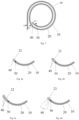
- Fig. 1 is a first plan view of an implantable stretchable flexible neural electrode according to an embodiment of the present disclosure
- Fig. 2 is a second plan view of an implantable stretchable flexible neural electrode according to an embodiment of the present disclosure
- Fig. 3 is a third plan view of an implantable stretchable flexible neural electrode according to an embodiment of the present disclosure.
- an implantable stretchable flexible neural electrode includes an electrode wire 10 and a flexible insulating part 20 wrapping the electrode wire 10; the implantable stretchable flexible neural electrode according to the embodiment of the present disclosure further includes a spiral structure SS of the electrode wire 10 and the flexible insulating part 20, and the spiral structure SS is stretchable; an electrode site 30 and an auxiliary implantation structure 40 are provided at the spiral structure SS, and the electrode site 30 is electrically connected to the electrode wire 10 and exposed from the flexible insulating part 20, and the auxiliary implantation structure 40 is configured to drive the spiral structure SS to stretch under the action of an external force.
- the flexible neural electrode includes a spiral structure SS of the electrode wire 10 and the flexible insulating part 20, and the spiral structure SS is stretchable.
- the spiral structure SS can greatly increase the implantation depth of flexible neural electrodes in target tissues (for example, brain tissues); for example, in a case where the spiral structure has a circle shape by way of example, the implantation depth of a two-circle spiral structure with a diameter of 1 mm can reach about 6 mm, and the implantation depth of a four-circle spiral structure with a diameter of 1 mm can reach about 12 mm; for another example, still in the case where the spiral structure has a circle shape by way of example, the implantation depth of a two-circle spiral structure with a diameter of 3 mm can reach about 12 mm, and the implantation depth of a four-circle spiral structure with a diameter of 3 mm can reach about 25 mm; therefore, designing the flexible neural electrode into a spiral structure SS including the electrode wire 10 and the flexible insulating part 20, and the spiral structure SS is
- the spiral structure SS has good stretchability, which can realize large-scale stretching in different directions and distances, thus improving the operational flexibility of implanting the flexible neural electrode into the target tissue.
- the spiral structure SS has good mechanical stability, and can still ensure good structural stability when it is stretched over a large range to be transformed from a planar spiral structure into a three-dimensional curve, which ensures the stability of the flexible neural electrode after being implanted into the target tissue.
- the spiral structure SS according to the embodiment of the present disclosure is a regular or irregular looped structure in which any straight line and any curve are combined. Therefore, the spiral structure SS according to the embodiment of the present disclosure includes at least one circle of electrode wire 10 and flexible insulating part 20.
- the number of circles of the electrode wire 10 and the flexible insulating part 20 in the spiral structure SS is 1 to 100,000 circles, such as, 1 circle, 10 circles, 50 circles, 100 circles, 300 circles, 500 circles, 700 circles or 1,000 circles, and so on.
- the number of circles of the electrode wire 10 and the flexible insulating part 20 in the spiral structure SS is more than 1 circle, such as more than 1 circle, 2 circles, 10 circles, 50 circles, 100 circles, 300 circles, 500 circles, 700 circles or 1000 circles, and so on.
- Figs. 1 and 3 show that the spiral structure SS includes two circles of electrode wire 10 and flexible insulating part 20, and Fig. 2 shows that the spiral structure SS includes more than one circle of electrode wire 10 and flexible insulating part 20.
- the spiral structure SS is stretchable; further, for example, the spiral structure SS is configured to be stretchable in any direction.
- the spiral structure SS is a regular or irregular looped structure in which any straight line and any curve are combined.
- one circle of the spiral structure SS is generally circular; however, the embodiment of the present disclosure does not limit the shape of the one circle of the spiral structure SS.
- one circle of the spiral structure SS can be generally circular, elliptical, triangular, square, rectangular or arbitrary polygon;
- one circle of the spiral structure SS can also be generally a rounded triangle, a rounded square, a rounded rectangle or any rounded polygon.
- the machining accuracy of rounded polygons is less than that of normal polygons.
- FIGS. 4a-4f are schematic diagrams of spiral structures of implantable stretchable flexible neural electrodes according to embodiments of the present disclosure, respectively.
- Figs. 4a and 4b show that one circle of the spiral structure SS is generally elliptical, and the difference between Figs. 4a and 4b is that the direction of the long axis of the ellipse in Fig. 4a is different from that of the ellipse in Fig. 4b .
- Figs. 4d and 4e show that one circle of the spiral structure SS is generally a rounded rectangle, and the difference between Figs. 4d and 4e is that the direction of the long side of the rounded rectangle in Fig.
- Fig. 4d is different from that of the rounded rectangle in Fig. 4e .
- Fig. 4c shows that one circle of the spiral structure SS is generally a rounded triangle
- Fig. 4f shows that one circle of the spiral structure is generally a rounded hexagon.
- the electrode wire 10 and the flexible insulating part 20 are not specifically shown in Figs. 4a to 4f , but only the spiral pattern of their spiral structure SS is shown.
- the maximum size of the spiral structure SS is 0.1 mm to 2 cm, such as 1 mm, 3 mm, 5 mm, 7 mm, 1 cm or 2 cm, and so on. If the overall size of the spiral structure SS in a certain direction is larger than all the sizes in other directions, the size of the spiral structure SS in the certain direction is the maximum size of the spiral structure SS.
- the maximum size of the spiral structure SS is the size of the long axis of ellipse at the outermost circle, which is 0.1 mm to 2 cm.
- the height of the cross section of one circle thereof (for example, referring to h in Fig. 13a) is 1 ⁇ m to 200 ⁇ m, preferably 2 ⁇ m; the width (for example, referring to w in Fig. 13a) of the cross section of one circle thereof is 1 ⁇ m to 2,000 ⁇ m, preferably 20 ⁇ m.
- the flexible insulating part 20 wrapping the electrode wire 10 means that the flexible insulating part 20 covers all the surfaces of the electrode wire 10 except the surface part of the electrode wire 10 that is in contact with other members.
- the flexible insulating part 20 is made of a flexible material with good biocompatibility and mechanical elasticity.
- the material of the flexible insulating part 20 includes at least one of polyimide (PI), Poly-p-xylene (Parylene C) and SU-8 photoresist.
- the material of the flexible insulating part 20 includes a combination of SU-8 photoresist and Parylene C, a combination of Parylene C and PI, or a combination of SU-8 photoresist, Parylene C and PI, etc. It is further preferable that the material of the flexible insulating part 20 is PI.
- the flexible insulating part 20 is transparent or translucent or opaque.
- the thickness of the flexible insulating part 20 is 1 ⁇ m to 200 ⁇ m, for example, 1 ⁇ m, 2 ⁇ m, 3 ⁇ m, 4 ⁇ m, 5 ⁇ m, 7 ⁇ m, 10 ⁇ m, 13 ⁇ m, 15 ⁇ m, 17 ⁇ m, 20 ⁇ m or 50 ⁇ m, etc.; further preferably, 2 ⁇ m.
- the thickness of the electrode wire 10 is 10 nm to 1000 nm, for example, 10 nm, 50 nm, 100 nm, 300 nm, 500 nm, 800 nm or 1000 nm, etc.; further preferably, 100 nm.
- the width of the electrode wire 10 (for example, referring to w' in Fig. 13a) is 1 ⁇ m to 200 ⁇ m, for example, 1 ⁇ m, 5 ⁇ m, 10 ⁇ m, 50 ⁇ m, 100 ⁇ m or 200 ⁇ m, etc.; further preferably, 20 ⁇ m.
- the electrode site 30 and the auxiliary implantation structure 40 are provided at the spiral structure SS
- the electrode site 30 and the auxiliary implantation structure 40 are provided on and/or connected to at least one circle of the spiral structure SS.
- the electrode site 30 is electrically connected to the electrode wire 10 and exposed from the flexible insulating part 20.
- the electrode site 30 collects biological information in the target tissue, and the biological information is transmitted to an external circuit via the electrode wire 10 electrically connected to the electrode site 30; and/or, after the flexible neural electrode is implanted into a target tissue (for example, brain tissue), an external circuit applies electric regulation information, which is transmitted to the electrode site 30 electrically connected to the electrode wire 10 via the electrode wire 10, and the electrode site 30 applies the electric regulation information to the target tissue.
- the electrode site 30 is exposed from the flexible insulating part 20, which can be understood as "the flexible insulating part 20 does not cover at least part of the electrode site 30".
- the electrode wire 10 and the electrode site 30 electrically connected to each other are formed of the same material or different materials, but the embodiment of the present disclosure does not limit thereto.
- the electrode wire 10 and the electrode site 30 electrically connected to each other are formed of the same material.
- the material of the electrode wire 10 and the electrode site 30 includes at least one of gold, platinum and iridium.
- the material of the electrode wire 10 and the electrode site 30 is a combination of gold and platinum, a combination of platinum and iridium, a combination of gold, platinum and iridium, or the like.
- the material of the electrode wire 10 and the electrode site 30 is gold. It should be noted that "the material of the electrode wire 10 and the electrode site 30 includes at least one of gold, platinum and iridium” means that at least the material of the outer surfaces of the electrode wire 10 and the electrode site 30 includes at least one of gold, platinum and iridium.
- the shape of the electrode site 30 is a semicircle, a large secant of a circle, a small secant of a circle, an ellipse or a circle, etc.; further preferably, a circle, as shown in Figs. 1-3 .
- the diameter of the circle is 1 ⁇ m to 100 ⁇ m, for example, 1 ⁇ m, 5 ⁇ m, 10 ⁇ m, 30 ⁇ m, 50 ⁇ m, 70 ⁇ m or 100 ⁇ m, etc.; further preferably, 20 ⁇ m.
- the arrangement of the electrode site 30 is not particularly limited as long as the electrode site 30 and the electrode wire 10 are electrically connected to each other.
- the electrode site 30 is located outside the electrode wire 10, and is electrically connected to the electrode wire 10 through a connection structure (for example, an anchoring electrode wire 62 as described below).
- the electrode site 30 is located on the electrode wire 10, that is, it is a part of the electrode wire 10; in this case, a part of the electrode wire 10 is exposed from the flexible insulating part 20 to serve as an electrode site 30.
- the spiral structure SS includes a plurality of circles, and any two adjacent circles among the plurality of circles are referred to as an inner circle and an outer circle, respectively; wherein the outer circle surrounds the inner circle, and a termination end of the outer circle is connected to an initial end of the inner circle.
- Fig. 5 is a schematic diagram of an inner circle and an outer circle of a spiral structure of an implantable stretchable flexible neural electrode according to an embodiment of the present disclosure. Referring to Fig.
- the part from point O to point O' is an outer circle
- the part from point O' to point O" is an inner circle.
- the outer circle OO' surrounds the inner circle O'O"
- the termination end of the outer circle OO' is connected to the initial end of the inner circle O'O".
- the termination end of the outer circle OO' and the initial end of the inner circle O'O" are indicated by the point O'.
- the plurality of circles of the spiral structure SS are basically a plurality of circles with the same shape.
- embodiments of the present disclosure are not limited thereto; the shapes of at least two circles of the spiral structure SS can be different from each other, which can be flexibly designed according to the actual situation.
- the plurality of circles of the spiral structure SS are basically arranged at equal intervals.
- embodiments of the present disclosure are not limited thereto; the plurality of circles of the spiral structure SS can be arranged at different intervals, which can be flexibly designed according to the actual situation.
- the distance between the inner circle and the outer circle of the spiral structure SS is equal everywhere.
- embodiments of the present disclosure are not limited thereto; the distance between the inner circle and the outer circle of the spiral structure SS can be varied, which can also be designed flexibly according to the actual situation.
- the auxiliary implantation structure 40 is configured to drive the spiral structure SS to stretch under the action of an external force. That is, according to the embodiment of the present disclosure, on the one hand, the auxiliary implantation structure 40 has a function of assisting implantation, and can drive at least part of the flexible neural electrode to be implanted into the target tissue; and on the other hand, the auxiliary implantation structure 40 can also drive at least part of the spiral structure SS to stretch.
- the auxiliary implant structure 40 is provided at the innermost circle among the plurality of circles of the spiral structure SS, that is, provided on and/or connected to the innermost circle.
- the auxiliary implantation structure 40 is provided at the termination end of the innermost circle among the plurality of circles of the spiral structure SS, so as to better realize the functions of assisting implantation and stretching the spiral structure SS. It should be noted that the arrangement position of the electrode site 30 is more flexible than that of the auxiliary implantation structure 40, and the electrode site 30 can be provided at the innermost circle and/or other circles of the spiral structure SS.
- the flexible insulating part 20 has a protruding part 21 extending beyond the electrode wire 10, and the auxiliary implantation structure 40 is a through hole, a groove or a protrusion provided at the protruding part 21.
- the auxiliary implantation structure 40 is a through hole or a groove
- an auxiliary implantation instrument cooperating with the auxiliary implantation structure 40 may have a protrusion engaged with the through hole or the groove; in the case where the auxiliary implantation structure 40 is a protrusion, the auxiliary implantation instrument cooperating with the auxiliary implantation structure 40 may have a hole or a recess engaged with the protrusion.
- FIGS. 6a-6d are schematic diagrams of the auxiliary implantation structure of the implantable stretchable flexible neural electrode according to the embodiment of the present disclosure, respectively.
- Figs. 6a-6d show the auxiliary implant structure 40 as a through hole.
- the embodiment of the present disclosure does not limit the number of the auxiliary implant structure 40, for example, the number of the auxiliary implant structure 40 may be one or more.
- Figs. 6b-6d show a plurality of auxiliary implantation structures 40.
- Fig. 6c shows one arrangement mode of three auxiliary implant structures 40
- Fig. 6d shows another arrangement mode of three auxiliary implant structures 40.
- Fig. 7 is a fourth plan view of an implantable stretchable flexible neural electrode according to an embodiment of the present disclosure.
- a position mark 50 is provided on the protruding part 21.
- the position mark 50 is provided at the same layer as the electrode wire 10 and made of the same material as the electrode wire 10, so that the position mark 50 and the electrode wire 10 can be formed in the same patterning process, and the manufacturing process is simplified.
- the position mark 50 is not limited to be provided at the protruding part 21, but may be provided at any required position according to the situation.
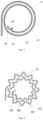
- Fig. 8 is a fifth plan view of an implantable stretchable flexible neural electrode according to an embodiment of the present disclosure.
- each circle of a plurality of circles of the spiral structure SS includes a plurality of curved portions connected in sequence, thereby further improving the achievable length of the flexible neural electrode in the effective area.
- the plurality of circles of the spiral structure SS may include the same or different curved portions, and only some circles of the spiral structure SS may include the curved portions, and the embodiment of the present disclosure does not limit thereto.
- the flexible neural electrode according to the embodiment of the present disclosure may include only the spiral structure SS, and may also include other structures besides the spiral structure SS.
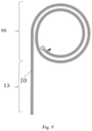
- Fig. 9 is a sixth plan view of an implantable stretchable flexible neural electrode according to an embodiment of the present disclosure.
- the flexible neural electrode according to the embodiment of the present disclosure further includes a linear structure LS of the electrode wire 10 and the flexible insulating part 20, and the linear structure LS is connected to the spiral structure SS.
- the flexible neural electrode including the linear structure LS may make the connection between the flexible neural electrode and the external circuit more convenient.
- the linear structure SS does not necessarily have to be a straight line, as long as its size in one direction is much greater than that in other directions; therefore, according to the embodiment of the present disclosure, the linear structure SS can be a straight line or a curve such as a broken line or a wavy line, which can be flexibly designed according to the situation.
- Fig. 9 shows that a straight angle exists between the linear structure LS and the initial end of the outer circle of the spiral structure SS; however, the embodiment of the present disclosure is not intended to make any limitation thereto, and any angle may exist between the linear structure LS and the initial end of the outer circle of the spiral structure SS.
- Fig. 10a is a seventh plan view of an implantable stretchable flexible neural electrode according to an embodiment of the present disclosure
- Fig. 10b is an eighth plan view of an implantable stretchable flexible neural electrode according to an embodiment of the present disclosure.
- the linear structure LS further includes an auxiliary electrode wire 11 wrapped by the flexible insulating part 20; and in the linear structure LS, the auxiliary electrode wire 11 is electrically connected to the electrode wire 10.
- the auxiliary electrode wire 11 By arranging the auxiliary electrode wire 11, the wiring length of the electrode wire 10 can be extended, thereby further improving the wiring flexibility of the flexible neural electrode according to the embodiment of the present disclosure.
- the electrode wire 10 and the auxiliary electrode wire 11 may be provided at the same layer or at different layers, may be formed of the same material or different materials, and may have the same size or different sizes, which is not limited in the embodiment of the present disclosure.
- the length of the auxiliary electrode wire 11 is 1 mm to 10 cm, for example, 1 mm, 3 mm, 5 mm, 7 mm, 1 cm or 5 cm, etc.; further preferably, 1 cm or 2.5 cm.
- the width of the auxiliary electrode wire 11 is 1 ⁇ m to 50 ⁇ m, for example, 1 ⁇ m, 5 ⁇ m, 10 ⁇ m, 20 ⁇ m, 30 ⁇ m, 40 ⁇ m or 50 ⁇ m, etc.; further preferably, 1.5 ⁇ m.
- the linear structure LS includes a plurality of auxiliary electrode wires 11 wrapped by the flexible insulating part 20, wherein the plurality of auxiliary electrode wires 11 are insulated from each other and electrically connected to the electrode wire 10, respectively.
- the plurality of auxiliary electrode wires 11 are provided, when one auxiliary electrode wire 11 fails, another auxiliary electrode wire 11 can be utilized, thereby enhancing the reliability of the flexible neural electrode according to the embodiment of the present disclosure.
- Fig. 11a is a ninth plan view of an implantable stretchable flexible neural electrode according to an embodiment of the present disclosure.
- the implantable stretchable flexible neural electrode according to the embodiment of the present disclosure further includes an anchoring structure 60; there is an angle between the anchoring structure 60 and the electrode wire 10, and the anchoring structure 60 is configured to be interacted with the target tissue after the flexible neural electrode is implanted into the target tissue so as to prevent the flexible neural electrode from moving relative to the target tissue.
- the anchoring structure 60 By arranging the anchoring structure 60, the part of the flexible neural electrode implanted into the target tissue can be more stably maintained in the target tissue, so that the flexible neural electrode can stably detect or regulate the target tissue.
- the angle can be any angle as long as the anchoring structure 60 interacts with the target tissue to prevent the flexible neural electrode from moving relative to the target tissue.
- the anchoring structure 60 protrudes from the flexible insulating part 20 that wraps the electrode wire 10.
- the number of the anchoring structures 60 is 1-20, such as 1, 4, 8, 16 or 20, which is not limited in the embodiment of the present disclosure.
- a plurality of anchoring structures 60 are provided; in this case, the plurality of anchoring structures 60 may be located at the same side or different sides of the electrode wire 10, and the shapes of the plurality of anchoring structures 60 may be the same or different, which is not limited in the embodiment of the present disclosure.
- the anchoring structure 60 along a direction away from the electrode wire 10, the anchoring structure 60 may change from wide to narrow, from narrow to wide, or sometimes narrow and sometimes wide, or maintain constant width, which is not limited in the embodiment of the present disclosure.
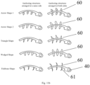
- Fig. 11b is a schematic diagram of an anchoring structure of an implantable stretchable flexible neural electrode according to an embodiment of the present disclosure. As an example, Fig.
- the anchoring structure 60 can be an arrow-shaped structure with a thickened end (see arrow shape 1, for example), an arrow-shaped structure with a tapered end (see arrow shape 2, for example), a triangular structure (see the triangular shape, for example), a wedge-shaped structure (see the wedged shape, for example), or a fishbone-shaped structure (see the fishbone shape, for example).
- the embodiment of the present disclosure is not limited thereto, and the shape of the anchoring structure 60 can be flexibly designed as required, as long as the anchoring structure 60 interacts with the target tissue after the flexible neural electrode is implanted into the target tissue to prevent the flexible neural electrode from moving relative to the target tissue.
- the left column shows a plurality of anchoring structures 60 located at the same side of the electrode wire 10
- the right column shows a plurality of anchoring structures 60 located at both sides of the electrode wire 10, respectively.
- the number of the anchoring structures 60 located at both sides of the electrode wire 10 may be equal or unequal, which is not limited in the embodiment of the present disclosure.
- the edge of the anchoring structure 60 extending from the electrode wire 10 in a direction away from the electrode wire 10 is an arc shape 61, and the arc shape 61 protrudes towards the auxiliary implantation structure 40.
- the arc shape 61 protruding towards the auxiliary implantation structure 40 the implantation process of the flexible neural electrode according to the embodiment of the present disclosure can be made smoother.
- the anchoring structure 60 includes an anchoring electrode wire 62 covered by the flexible insulating part 20, and the electrode site 30 is electrically connected to the electrode wire 10 through the anchoring electrode wire 62.
- the anchoring structure 60 may be only a protrusion of the flexible insulating part 20 without including the anchoring electrode wire 62.
- Fig. 12 is a tenth plan view of an implantable stretchable flexible neural electrode according to an embodiment of the present disclosure.
- Figs. 13a and 13b are schematic cross-sectional views taken along A-A of Fig. 12 , respectively, that is, Figs. 13a and 13b are schematic cross-sectional views of one circle of the spiral structure SS shown in Fig. 12 .
- a flexible neural electrode according to an embodiment of the present disclosure includes a plurality of electrode wires 10 wrapped by a flexible insulating part 20 and insulated from each other; and a plurality of electrode sites 30 exposed from the flexible insulating part 20, electrically connected to the plurality of electrode wires 10 in one-to-one correspondence, and spatially separated from each other.
- the flexible neural electrode according to the embodiment of the present disclosure includes a plurality of electrode wires 10
- each circle of the spiral structure SS of the flexible neural electrode includes the plurality of electrode wires 10.
- the number of the plurality of electrode wires 10 is 1 to 10000, for example, 1, 10, 50, 100, 300, 500, 700 or 1000, etc., and more preferably, 10; accordingly, the number of the plurality of electrode sites is 1 to 10000, for example, 1, 10, 50, 100, 300, 500, 700 or 1000, etc., and more preferably, 10.
- the plurality of electrode sites 30 can monitor and/or regulate a plurality of positions of the target tissue, thereby greatly improving the monitoring and/or regulating effect of the flexible neural electrode according to the embodiment of the present disclosure.
- the plurality of electrode sites 30 are spatially separated from each other by about 70 ⁇ m.
- Figs. 12 , 13a and 13b show 5 electrode wires 10 and 5 electrode sites 30.
- the implantable stretchable flexible neural electrode according to the embodiment of the present disclosure further includes an adhesive layer 70 provided between the electrode wire 10 and the flexible insulating part 20.
- the adhesive layer 70 By arranging the adhesive layer 70, the bonding strength between the electrode wire 10 and the flexible insulating part 20 can be enhanced, and the structure of the flexible neural electrode is more stable.
- the material of the adhesive layer 70 includes chromium or titanium; further preferably, chromium.
- the thickness of the adhesive layer 70 is 1 nm to 100 nm, for example, 1 nm, 5 nm, 10 nm, 20 nm, 30 nm, 40 nm, 50 nm, 60 nm, 70 nm, 80 nm, 90 nm or 100 nm; further preferably, 5 nm.
- the flexible neural electrode according to the embodiment of the present disclosure includes a plurality of electrode wires 10 located at a plurality of layers provided in a stacked manner, and each of the plurality of layers includes at least one of the plurality of electrode wires 10.
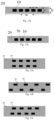
- each layer may include one electrode wire 10 or a plurality of electrode wires 10, and the number of electrode wires 10 included in each layer may be equal or unequal, which is not limited in the embodiment of the present disclosure.
- FIGS. 14a-14c are schematic cross-sectional views of an implantable stretchable flexible neural electrode according to an embodiment of the present disclosure, respectively.
- Figs. 14a-14c show 10 electrode wires 10, of which 5 electrode wires 10 are provided at a lower layer and the other 5 electrode wires are provided at an upper layer.
- any two adjacent layers among the plurality of layers are referred to as a first layer and a second layer, respectively; in the stacking direction of the plurality of layers, the electrode wire 10 located at the first layer at least partially overlaps or at least partially does not overlap with the electrode wire 10 located at the second layer.
- Fig. 14a shows that the electrode wire 10 located at the first layer completely overlaps with the electrode wire 10 located at the second layer in the stacking direction;
- Fig. 14b shows that the electrode wire 10 located at the first layer does not completely overlap with the electrode wire 10 located at the second layer in the stacking direction;
- Fig. 14c shows that the electrode wire 10 located at the first layer partially overlaps and partially does not overlap with the electrode wire 10 located at the second layer in the stacking direction.
- the electrode wire 10 located at the first layer and the electrode wire 10 located at the second layer are implanted into the target tissue simultaneously.
- the electrode wire 10 located at the first layer and the electrode wire 10 located at the second layer are alternately implanted into the target tissue.
- the plurality of electrode sites 30 are located at the same side of the flexible neural electrode.
- the embodiment of the present disclosure is not limited thereto, and the plurality of the electrode sites 30 may be located at the same side of the flexible neural electrode or located at different sides of the flexible neural electrode.
- the plurality of electrode sites 30 are sequentially arranged, so that the plurality of electrode sites 30 are sequentially implanted into a target tissue at different depths of the target tissue.
- the embodiment of the present disclosure is not limited thereto.
- the plurality of electrode sites 30 may also be arranged at a plurality of layers so that the plurality of electrode sites 30 are simultaneously implanted into the target tissue and located at different positions at the same depth of the target tissue.
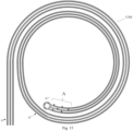
- Fig. 15 is a first plan view of an implantable stretchable flexible neural electrode group according to an embodiment of the present disclosure; and Figs. 16a-16c are enlarged views of part A of Fig. 15 . Referring to Fig. 15 and Figs.
- an implantable stretchable flexible neural electrode group includes a plurality of flexible neural electrodes as described above; the plurality of flexible neural electrodes are insulated from each other; a plurality of spiral structures SS of flexible neural electrodes as described above forms a composite spiral structure CSS, and in a same circle of the composite spiral structure CSS, the parts of the plurality of spiral structures SS located in the same circle are sequentially arranged from inside to outside.
- a plurality of electrode sites 30 of the plurality of flexible neural electrodes are spatially separated from each other, which can avoid mutual interference between the plurality of electrode sites 30 and is beneficial for the plurality of electrode sites 30 to be dispersed in different positions of the target tissue after being implanted into the target tissue (for example, brain tissue).
- the target tissue for example, brain tissue.
- the mechanical properties of the flexible neural electrode group are matched with the target tissue (for example, brain tissue) without causing an inflammatory reaction of the target tissue, and the target tissue can be stably monitored and/or regulated at multiple points for a long time.
- the number of the flexible neural electrodes included in the flexible neural electrode group and the number of the electrode wires 10 included in each flexible neural electrode are not limited in the embodiment of the present disclosure.
- the arrangement of all the electrode sites included in the flexible neural electrode group is not limited in the embodiment of the present disclosure, and these electrode sites can be provided such that they are implanted into the target tissue sequentially or simultaneously, or a part of these electrode sites can be implanted into the target tissue sequentially and the other part can be implanted into the target tissue simultaneously.
- the flexible neural electrode group shown in Figs. 15 and Figs. 16a-16c includes three flexible neural electrodes as described above, and each flexible neural electrode includes two electrode wires 10 and two electrode sites 30.
- the plurality of flexible neural electrodes are insulated from each other, which means that the electrode wires 10 of the plurality of flexible neural electrodes are insulated from each other, and the plurality of electrode sites 30 of the plurality of flexible neural electrodes are also insulated from each other.
- the composite spiral structure CSS is stretchable; further, for example, the composite spiral structure CSS is configured to be stretchable in any direction, so that the flexibility of operation of implanting the flexible neural electrode group into the target tissue is greatly improved.
- the composite spiral structure CSS includes a plurality of circles, and any two adjacent circles among the plurality of circles are referred to as an inner circle and an outer circle, respectively, wherein the outer circle surrounds the inner circle, and the termination end of the outer circle is connected to the initial end of the inner circle; in each circle of the plurality of circles of the composite spiral structure CSS, the corresponding parts of the plurality of spiral structures SS are sequentially arranged from inside to outside in the same order.
- the plurality of circles of the composite spiral structure CSS are arranged more orderly without being intersected with each other, and the plurality of spiral structures SS of the plurality of flexible neural electrodes are also orderly arranged without being intersected with each other, so that the composite spiral structure CSS can be conveniently manufactured by a patterning process such as photolithography and that the stretching process of the composite spiral structure CSS is smoother.
- the part from point O to point O' is an outer circle
- the part from point O' to point O" is an inner circle.
- the outer circle OO' surrounds the inner circle O'O"
- the termination end of the outer circle OO' is connected to the initial end of the inner circle O'O".
- the termination end of the outer circle OO' and the initial end of the inner circle O'O" are indicated by the point O'.
- the plurality of auxiliary implantation structures 40 of the plurality of flexible neural electrodes included in the flexible neural electrode group are integrated into a common auxiliary structure 40S, which is configured to drive the plurality of spiral structures SS of the plurality of flexible neural electrodes to stretch synchronously under the action of an external force.
- a common auxiliary structure 40S which is configured to drive the plurality of spiral structures SS of the plurality of flexible neural electrodes to stretch synchronously under the action of an external force.
- the plurality of flexible insulating parts 20 of the plurality of flexible neural electrodes are at least partially connected to each other, so that the structural stability of the composite spiral structure CSS can be enhanced.
- the difference between Fig. 16b and Fig. 16c is that the connection positions of the plurality of flexible insulating parts 20 are different, and the embodiment of the present disclosure does not limit the connection positions of the plurality of flexible insulating parts 20.
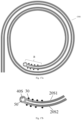
- Fig. 17a is a second plan view of an implantable stretchable flexible neural electrode group according to an embodiment of the present disclosure
- Fig. 17b is an enlarged view of part B of Fig. 17a .
- the plurality of flexible neural electrodes included in the flexible neural electrode group are divided into a first subgroup and a second subgroup; the flexible insulating parts 20 of all the flexible neural electrodes included in the first subgroup are integrated into a first common flexible insulating part 20S1; the flexible insulating parts 20 of all the flexible neural electrodes included in the second subgroup are integrated into a second common flexible insulating part 20S2.
- the structure of the flexible neural electrode group is made simpler.
- the number of the flexible neural electrodes included in the first subgroup and the number of the flexible neural electrodes included in the second subgroup may be the same or different.
- the number of the electrode wires 10 included in the first subgroup may be the same as or different from the number of the electrode wires 10 included in the second subgroup.
- Figs. 17a and 17b show that the first subgroup includes four electrode wires 10 and the second subgroup includes four electrode wires 10. For example, referring to Figs.
- the plurality of electrode sites 30 of the plurality of flexible neural electrodes included in the first subgroup are located at the side of the first subgroup away from the second subgroup, and the plurality of electrode sites 30 of the plurality of flexible neural electrodes included in the second subgroup are located at the side of the second subgroup away from the first subgroup; in this way, interference between the electrode sites 30 can be avoided.
- the plurality of auxiliary implantation structures 40 of the plurality of flexible neural electrodes are integrated into a common auxiliary structure 40S, which is configured to drive the spiral structures SS of all the flexible neural electrodes included in the first subgroup and the second subgroup to stretch synchronously under the action of an external force.
- the structure of the flexible neural electrode group can be made simpler, and the plurality of flexible neural electrodes included in the flexible neural electrode group can be implanted synchronously, and the plurality of spiral structures SS of the plurality of flexible neural electrodes can be stretched synchronously, thereby improving the implantation efficiency.
- the first common flexible insulating part 20S1 and the second common flexible insulating part 20S2 are at least partially connected, so that the structural stability of the composite spiral structure CSS can be enhanced.
- Fig. 18 is a third plan view of an implantable stretchable flexible neural electrode group according to an embodiment of the present disclosure.
- the plurality of auxiliary implant structures 40 of the plurality of flexible neural electrodes are spatially separated from each other; in this way, multi-point implantation can be realized, so that the implantation position of each flexible neural electrode can be selected more flexibly according to actual needs, and the implantation density can be improved.
- the embodiment of the present disclosure does not limit the spaced distance between the plurality of auxiliary implantation structures 40, as long as they do not interfere with each other for implantation.
- each of the plurality of flexible neural electrodes included in the flexible neural electrode group further includes a linear structure of the electrode wire 10 and the flexible insulating part 20.
- the design of the linear structure reference can be made to the previous description, which will not be repeated here.
- an implantable stretchable flexible neural electrode array is also provided.
- Fig. 19 is a plan view of an implantable stretchable flexible neural electrode array according to an embodiment of the present disclosure.
- the flexible neural electrode array according to the embodiment of the present disclosure includes a plurality of flexible neural electrodes as described above, the plurality of flexible neural electrodes are insulated from each other, and the plurality of spiral structures SS of the plurality of flexible neural electrodes are arranged in an array.
- the plurality of spiral structures SS included in the array can be synchronously transferred and implanted, which is convenient to operate and improves the efficiency.
- each spiral structure SS included in the flexible neural electrode array is stretchable; further, each spiral structure SS included in the flexible neural electrode array is stretchable in any direction.
- the mechanical properties of the flexible neural electrode array are matched with the target tissue (for example, brain tissue) without causing an inflammatory reaction of the target tissue, so that the target tissue can be stably monitored and/or regulated at multiple points for a long time.
- the array in which the spiral structures SS are arranged may be a regular array or an irregular array. By comparison, the regular array is more convenient for operation than the irregular array.
- the embodiment of the present disclosure does not limit the number of the spiral structures SS included in the array. As an example, Fig. 19 shows that 12 spiral structures SS are arranged in a regular 3x4 array.
- each of the plurality of flexible neural electrodes included in the flexible neural electrode array includes a linear structure LS of the electrode wire 10 and the flexible insulating part 20, and the linear structure LS is connected to the spiral structure SS.
- the plurality of flexible neural electrodes included in the flexible neural electrode array can be more conveniently connected to an external circuit 90.
- each electrode wire 10 is connected to a pad 80, and the pad 80, in turn, is connected to the external circuit 90; that is, the electrode wire 10 is connected to the external circuit 90 through the pad 80 connected thereto.
- the sizes of various parts shown in Fig. 19 are only exemplary, and should not be regarded as limitations on the embodiment of the present disclosure.
- the plurality of linear structures LS of the plurality of flexible neural electrodes included in the flexible neural electrode array are located at the same side of an array formed by the spiral structures SS.
- the embodiment of the present disclosure is not limited thereto, and the plurality of linear structures LS of the plurality of flexible neural electrodes included in the flexible neural electrode array can also be located at two opposite sides, two adjacent sides, three sides or multiple sides of an array formed by the spiral structures SS, which can be flexibly designed according to the actual situation.
- an implantable stretchable flexible neural electrode array is also provided.
- the flexible neural electrode array according to the embodiment of the present disclosure includes a plurality of flexible neural electrode groups as described above, and the plurality of composite spiral structures CSS of the plurality of flexible neural electrode groups are arranged in an array.
- the plurality of spiral structures SS included in the array can be synchronously transferred and implanted, which is convenient to operate and improves the efficiency; furthermore, the array can include more electrode sites 30, so that the monitoring efficiency and/or regulating efficiency of the technical solution according to the embodiment of the present disclosure is improved.
- each composite spiral structure CSS included in the flexible neural electrode array is stretchable; further, each composite spiral structure CSS included in the flexible neural electrode array is stretchable in any direction.
- the array formed by the composite spiral structures CSS can be a regular array or an irregular array.
- the regular array is more convenient for operation than the irregular array.
- the embodiment of the present disclosure does not limit the number of the composite spiral structures CSS included in the array.
- Fig. 19 shows that 12 composite spiral structures CSS are arranged in a regular 3x4 array.
- each of all the flexible neural electrodes included in the plurality of flexible neural electrode groups includes a linear structure LS of the electrode wire 10 and the flexible insulating part 20, and the linear structure LS is connected to the spiral structure SS.
- all the flexible neural electrodes included in the flexible neural electrode array can be connected to an external circuit 90 more conveniently.
- each electrode wire 10 is connected to a pad 80, and the pad 80, in turn, is connected to the external circuit 90; that is, the electrode wire 10 is connected to the external circuit 90 through the pad 80 connected thereto.
- the sizes of various parts shown in Fig. 19 are only exemplary, and should not be regarded as limitations on the embodiment of the present disclosure.
- all the linear structures LS of all the flexible neural electrodes included in the flexible neural electrode array are located at the same side of an array formed by the composite spiral structures CSS.
- the embodiment of the present disclosure is not limited thereto, and all the linear structures LS of all the flexible neural electrodes included in the flexible neural electrode array can also be located at two opposite sides, two adjacent sides, three sides or multiple sides of an array formed by the composite spiral structures CSS, which can be flexibly designed according to the actual situation.
- a manufacturing method is also provided, which can be used for manufacturing the implantable stretchable flexible neural electrode, the implantable stretchable flexible neural electrode group and the implantable stretchable flexible neural electrode array as described above.
- the manufacturing method of the implantable stretchable flexible neural electrode will be described below; it should be noted that this method can be used to manufacture the implantable stretchable flexible neural electrode group and the implantable stretchable flexible neural electrode array.
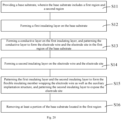
- Fig. 20 is a flowchart of a manufacturing method of an implantable stretchable flexible neural electrode according to an embodiment of the present disclosure
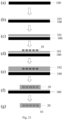
- Fig. 21 is a schematic cross-sectional view of various steps in the manufacturing method of the implantable stretchable flexible neural electrode according to the embodiment of the present disclosure.
- the manufacturing method of the implantable stretchable flexible neural electrode includes the following steps: step S11, providing a base substrate 100, wherein the base substrate 100 includes a first region and a second region, as shown in the cross-sectional view (a) of Fig. 21 ; S12, forming a first insulating layer 101 on the base substrate 100, as shown in the cross-sectional view (c) of Fig. 21 ; S13, forming a conductive layer on the first insulating layer 101, and patterning the conductive layer to form the electrode wire 10 and the electrode site 30 in the first region of the base substrate 101, as shown in the cross-sectional view (d) of Fig.
- step S14 forming a second insulating layer 102 on the electrode wire 10 and the electrode site 30, as shown in the cross-sectional view (e) of Fig. 21 ; step S15, patterning the first insulating layer 101 and the second insulating layer 102 to form the flexible insulating part 20 wrapping the electrode wire 10, the auxiliary implantation structure 40, as well as the spiral structure SS of the electrode wire 10 and the flexible insulating part 20, and patterning the second insulating layer 102 to expose the electrode site 30, as shown in the cross-sectional view (f) of Fig. 21 ; and step S16, removing at least a portion of the base substrate 100 located in the first region, as shown in the cross-sectional view (g) of Fig. 21 .
- the base substrate 100 is a silicon wafer or a glass sheet; providing the base substrate 100 includes pretreating the base substrate 100, for example, the base substrate 100 is cleaned with acetone and isopropanol, then is cleaned with water and oven-dried, and then is cleaned with oxygen plasma.
- the portion of the base substrate 100 located in the second region is retained or removed; further preferably, the portion of the base substrate 100 located in the second region is retained so as to reduce the operational difficulty of removing the base substrate 100 and ensure the structural stability of the pad 80 in the second region.
- the "patterning" process in steps S13 and S15 includes coating, exposure and development of photoresist to form a photoresist pattern, and forming a desired pattern for each layer by using the photoresist pattern as a mask.
- the manufacturing method of the implantable stretchable flexible neural electrode further includes: before forming the first insulating layer 101 on the base substrate 100, forming a sacrificial layer 103 at least in the first region of the base substrate 100, as shown in the cross-sectional view (b) of Fig. 21 ; removing at least a portion of the base substrate 100 located in the first region includes: removing the sacrificial layer 103 and cutting the base substrate 100 to remove at least a portion of the base substrate 100 located in the first region.
- the thickness of the sacrificial layer 103 is 10 nm to 1000 nm, for example, 10 nm, 30 nm, 50 nm, 70 nm, 100 nm, 300 nm, 500 nm, 700 nm or 1000 nm; further preferably, 100 nm.
- the material of the sacrificial layer 103 includes at least one of aluminum, PMMA and nickel; further preferably, aluminum.
- step S13 further includes: patterning the conductive layer to form the pad 80 in the second region of the base substrate 100 while forming the electrode wire 10 and the electrode site 30 in the first region of the base substrate 100, wherein the electrode wire 10 is electrically connected to the pad 80; and step S15 further includes: patterning the second insulating layer 102 to expose the pad 80.
- the size of the pad 80 is (0.1 to 4) mm ⁇ (0.1 to 4) mm, for example, 0.1 mm ⁇ 0.1 mm, 0.2 mm ⁇ 0.1 mm, 1 mm ⁇ 2 mm, 3.5 mm ⁇ 3.5 mm, 3.7 mm ⁇ 4 mm, 4 mm ⁇ 4 mm or 4 mm ⁇ 3.7 mm, etc.; further preferably, 0.1 mm ⁇ 0.2 mm.
- Fig. 22 is an exploded view of an implantable stretchable flexible neural electrode which is manufactured according to an embodiment of the present disclosure.
- Fig. 22 (a) shows the patterned first insulating layer 101
- Fig. 22 (b) shows the electrode wire 10 and the electrode site 30 connected thereto
- Fig. 22 (c) shows the patterned second insulating layer 102.
- the patterned second insulating layer 102 includes an opening 20h1 to expose the electrode site 30.
- Fig. 23 is an exploded view of an implantable stretchable flexible neural electrode array which is manufactured according to an embodiment of the present disclosure.
- Fig. 22 (a) shows the patterned first insulating layer 101
- Fig. 22 (b) shows the electrode wire 10 and the pad 80 connected thereto
- Fig. 22 (c) shows the patterned second insulating layer 102.
- the patterned second insulating layer 102 includes an opening 20h2 to expose the pad 80.
- Fig. 22 is the exploded view of each of a plurality of flexible neural electrodes included in the flexible neural electrode array of Fig. 23 .
- an implantation method is also provided, which can be used for implanting the implantable stretchable flexible neural electrode, the implantable stretchable flexible neural electrode group, and the implantable stretchable flexible neural electrode array as described above into the target tissue.
- the implantation method of the implantable stretchable flexible neural electrode will be described below; it should be noted that this method can be used to implant the implantable stretchable flexible neural electrode group and the implantable stretchable flexible neural electrode array into the target tissue.
- Fig. 24 is a flowchart of an implantation method of an implantable stretchable flexible neural electrode according to an embodiment of the present disclosure
- Figs. 25a-25c are perspective views of various steps in the implantation method of the implantable stretchable flexible neural electrode according to the embodiment of the present disclosure.
- the implantation method of the implantable stretchable flexible neural electrode includes the following steps: step S21, applying an external force to the auxiliary implantation structure 40 by using an auxiliary implantation instrument 40' to implant at least part of the flexible neural electrode into a target tissue, and at least partially stretching the spiral structure SS under a drive of the external force in the process of implanting the at least part of the flexible neural electrode into the target tissue, as shown in Fig. 25b ; and step S22, removing the auxiliary implantation instrument 40' and leaving, in the target tissue, the at least part of the flexible neural electrode implanted in the target tissue, as shown in Fig. 25c .
- the implantation method further includes: assembling the auxiliary implantation instrument 40' with the auxiliary implantation structure 40, as shown in Fig. 25a .
- the auxiliary implantation structure 40 is a through hole, and the auxiliary implantation instrument 40' cooperating with the auxiliary implantation structure 40 has a protrusion engaged with the through hole.
- the embodiment of the present disclosure is not limited thereto, and in the case where the auxiliary implantation structure 40 is a protrusion, the auxiliary implantation instrument 40' cooperating with the auxiliary implantation structure 40 may have a hole or a groove engaged with the protrusion.
- all the electrode wires 10 can be stretched and implanted into the target tissue in situ, thereby improving the implantation density and reducing the difficulty of the implantation process.
Landscapes
- Health & Medical Sciences (AREA)
- Life Sciences & Earth Sciences (AREA)
- General Health & Medical Sciences (AREA)
- Veterinary Medicine (AREA)
- Engineering & Computer Science (AREA)
- Biomedical Technology (AREA)
- Heart & Thoracic Surgery (AREA)
- Animal Behavior & Ethology (AREA)
- Public Health (AREA)
- Neurosurgery (AREA)
- Neurology (AREA)
- Medical Informatics (AREA)
- Biophysics (AREA)
- Surgery (AREA)
- Molecular Biology (AREA)
- Physics & Mathematics (AREA)
- Pathology (AREA)
- Cardiology (AREA)
- Nuclear Medicine, Radiotherapy & Molecular Imaging (AREA)
- Radiology & Medical Imaging (AREA)
- Psychology (AREA)
- Orthopedic Medicine & Surgery (AREA)
- Psychiatry (AREA)
- Electrotherapy Devices (AREA)
Applications Claiming Priority (2)
| Application Number | Priority Date | Filing Date | Title |
|---|---|---|---|
| CN202210351191.0A CN116919408B (zh) | 2022-04-02 | 2022-04-02 | 植入式可拉伸柔性神经电极、电极组及电极阵列 |
| PCT/CN2023/085295 WO2023186052A1 (zh) | 2022-04-02 | 2023-03-31 | 植入式可拉伸柔性神经电极、电极组及电极阵列 |
Publications (2)
| Publication Number | Publication Date |
|---|---|
| EP4501236A1 true EP4501236A1 (de) | 2025-02-05 |
| EP4501236A4 EP4501236A4 (de) | 2025-05-14 |
Family
ID=88199476
Family Applications (1)
| Application Number | Title | Priority Date | Filing Date |
|---|---|---|---|
| EP23778417.8A Pending EP4501236A4 (de) | 2022-04-02 | 2023-03-31 | Implantierbare dehnbare flexible neurale elektrode, elektrodengruppe und elektrodenanordnung |
Country Status (3)
| Country | Link |
|---|---|
| EP (1) | EP4501236A4 (de) |
| CN (1) | CN116919408B (de) |
| WO (1) | WO2023186052A1 (de) |
Families Citing this family (6)
| Publication number | Priority date | Publication date | Assignee | Title |
|---|---|---|---|---|
| CN117982213B (zh) * | 2024-04-03 | 2024-06-07 | 北京智冉医疗科技有限公司 | 植入电极丝 |
| CN118121281B (zh) * | 2024-04-09 | 2025-01-21 | 北京智冉医疗科技有限公司 | 一种用于植入柔性神经电极的植入系统及植入方法 |
| CN119548756A (zh) * | 2025-01-24 | 2025-03-04 | 北京智冉医疗科技有限公司 | 柔性神经电极及其制备方法 |
| CN119867769B (zh) * | 2025-03-27 | 2025-12-05 | 北京智冉医疗科技有限公司 | 柔性神经电极组件及柔性神经电极的制备方法 |
| CN120814789A (zh) * | 2025-08-27 | 2025-10-21 | 中国科学院空天信息创新研究院 | 柔性可折叠的临床多功能神经探针及其制备方法 |
| CN121446035B (zh) * | 2026-01-08 | 2026-04-07 | 北京智冉医疗科技有限公司 | 柔性电极植入组件、临时神经刺激器系统及植入式神经刺激器系统 |
Family Cites Families (15)
| Publication number | Priority date | Publication date | Assignee | Title |
|---|---|---|---|---|
| CN102361665B (zh) * | 2009-02-06 | 2014-01-01 | Med-El电气医疗器械有限公司 | 具有可变机械调节布线的植入式电极 |
| KR101889567B1 (ko) * | 2010-06-30 | 2018-08-17 | 메드-엘 엘렉트로메디지니쉐 게라에테 게엠베하 | 귀 임플란트 전극 및 제조 방법 |
| US20120203245A1 (en) * | 2011-02-07 | 2012-08-09 | Olympus Corporation | Nerve stimulator |
| US9241651B2 (en) * | 2011-11-17 | 2016-01-26 | Carnegie Mellon University | Fabrication, methods, apparatuses, and systems for ultra-compliant probes for neural and other tissues |
| EP2653187A1 (de) * | 2012-04-20 | 2013-10-23 | Sapiens Steering Brain Stimulation B.V. | Freistehender Dünnfilm, insbesondere freistehender Dünnfilm für ein System für neurale Anwendungen |
| EP3347088B1 (de) * | 2015-09-08 | 2020-06-24 | Case Western Reserve University | Neurale elektroden |
| CN106667475B (zh) * | 2016-12-20 | 2019-05-07 | 国家纳米科学中心 | 一种植入式柔性神经微电极梳及其制备方法和植入方法 |
| CN107158560A (zh) * | 2017-04-27 | 2017-09-15 | 清华大学 | 基于水凝胶溶胀特性的可控自变形神经微电极 |
| US11647960B2 (en) * | 2017-08-28 | 2023-05-16 | Cortec Gmbh | Flexible neural electrode array |
| CN108939287B (zh) * | 2018-06-04 | 2020-09-04 | 清华大学 | 柔性螺旋电极的制造方法及神经束检测治疗装置 |
| CN109875555B (zh) * | 2019-03-05 | 2022-10-14 | 浙江中医药大学 | 一种非侵入性脑电图记录电极及其制作方法 |
| CN110840431A (zh) * | 2019-11-28 | 2020-02-28 | 中国科学院电子学研究所 | 柔性微纳电极阵列植入式芯片及其制备方法 |
| CN110876616A (zh) * | 2019-12-11 | 2020-03-13 | 中国科学院深圳先进技术研究院 | 自伸展记录电极及其制备方法及植入方法 |
| CN112617864A (zh) * | 2020-11-19 | 2021-04-09 | 南京医科大学 | 一种可自卷曲的外周神经电极及其制备方法 |
| CN113041496A (zh) * | 2021-03-19 | 2021-06-29 | 国家纳米科学中心 | 一种神经电刺激电极、其制备方法和植入方法 |
-
2022
- 2022-04-02 CN CN202210351191.0A patent/CN116919408B/zh active Active
-
2023
- 2023-03-31 WO PCT/CN2023/085295 patent/WO2023186052A1/zh not_active Ceased
- 2023-03-31 EP EP23778417.8A patent/EP4501236A4/de active Pending
Also Published As
| Publication number | Publication date |
|---|---|
| CN116919408A (zh) | 2023-10-24 |
| EP4501236A4 (de) | 2025-05-14 |
| WO2023186052A1 (zh) | 2023-10-05 |
| WO2023186052A9 (zh) | 2024-12-05 |
| CN116919408B (zh) | 2025-06-20 |
Similar Documents
| Publication | Publication Date | Title |
|---|---|---|
| CN116919408B (zh) | 植入式可拉伸柔性神经电极、电极组及电极阵列 | |
| US12144651B2 (en) | Flexible neural electrode array | |
| US11730953B2 (en) | Deep brain stimulation lead | |
| ES3018634T3 (es) | Catéter que comprende un cable plano flexible y una placa de circuito impreso flexible (FPCB) | |
| US8332046B2 (en) | Neural interface system | |
| WO2020137148A1 (ja) | フレキシブル配線基板及び電子機器 | |
| WO2012114501A1 (ja) | 脳プローブ及びその製造方法 | |
| CA2751569A1 (en) | Implantable electrode with variable mechanical modulation wiring | |
| EP4351702B1 (de) | Elektrodenvorrichtung | |
| JP2013543780A (ja) | 医療用プローブ及び当該医療用プローブの提供方法 | |
| CN112472096A (zh) | 一种应力诱发的自卷曲网状卡夫神经电极及其制备方法 | |
| JP5075016B2 (ja) | 刺入型柔軟神経電極およびその作製方法 | |
| KR100945170B1 (ko) | 적어도 하나의 나노 와이어를 이용하는 신경 소자 | |
| KR100943415B1 (ko) | 나노 와이어를 이용하여 전기신호를 전달하는 신경 소자 | |
| CN223169743U (zh) | 微电极阵列 | |
| JP2011030678A (ja) | 網状生体電極アレイ | |
| KR20110124575A (ko) | 관통 비아홀 연결을 포함하고 적어도 하나의 나노와이어를 이용하는 신경 소자 | |
| KR101158775B1 (ko) | 나노 와이어와 커프를 활용한 신경 소자 | |
| CN114515154A (zh) | 一种一体化脑电极结构及其制备方法 | |
| US20230181918A1 (en) | Transducer array with adhesive layer shaped to reduce skin irritation | |
| KR101218188B1 (ko) | 외부 모듈과 데이터 통신이 가능한 지능형 신경소자 | |
| KR102568398B1 (ko) | 뇌 삽입용 그래핀 복합 전극을 이용한 다중 채널 어레이 소자 | |
| KR102906961B1 (ko) | 뉴럴프로브 | |
| KR20150136286A (ko) | 전극 배열체 및 그 제조 방법 | |
| KR20090041658A (ko) | 신경에 삽입되는 마이크로칩 |
Legal Events
| Date | Code | Title | Description |
|---|---|---|---|
| STAA | Information on the status of an ep patent application or granted ep patent |
Free format text: STATUS: THE INTERNATIONAL PUBLICATION HAS BEEN MADE |
|
| PUAI | Public reference made under article 153(3) epc to a published international application that has entered the european phase |
Free format text: ORIGINAL CODE: 0009012 |
|
| STAA | Information on the status of an ep patent application or granted ep patent |
Free format text: STATUS: REQUEST FOR EXAMINATION WAS MADE |
|
| 17P | Request for examination filed |
Effective date: 20241030 |
|
| AK | Designated contracting states |
Kind code of ref document: A1 Designated state(s): AL AT BE BG CH CY CZ DE DK EE ES FI FR GB GR HR HU IE IS IT LI LT LU LV MC ME MK MT NL NO PL PT RO RS SE SI SK SM TR |
|
| A4 | Supplementary search report drawn up and despatched |
Effective date: 20250411 |
|
| RIC1 | Information provided on ipc code assigned before grant |
Ipc: A61N 1/05 20060101ALI20250407BHEP Ipc: A61B 5/37 20210101ALI20250407BHEP Ipc: A61B 5/31 20210101ALI20250407BHEP Ipc: A61B 5/388 20210101ALI20250407BHEP Ipc: A61B 5/293 20210101ALI20250407BHEP Ipc: A61B 5/291 20210101ALI20250407BHEP Ipc: A61B 5/294 20210101AFI20250407BHEP |
|
| DAV | Request for validation of the european patent (deleted) | ||
| DAX | Request for extension of the european patent (deleted) | ||
| STAA | Information on the status of an ep patent application or granted ep patent |
Free format text: STATUS: EXAMINATION IS IN PROGRESS |
|
| 17Q | First examination report despatched |
Effective date: 20260311 |