EP4501443A1 - Reaktor zur durchführung chemischer oder biologischer prozesse, verfahren unter verwendung des reaktors und verfahren zur herstellung eines rührers - Google Patents
Reaktor zur durchführung chemischer oder biologischer prozesse, verfahren unter verwendung des reaktors und verfahren zur herstellung eines rührers Download PDFInfo
- Publication number
- EP4501443A1 EP4501443A1 EP23189697.8A EP23189697A EP4501443A1 EP 4501443 A1 EP4501443 A1 EP 4501443A1 EP 23189697 A EP23189697 A EP 23189697A EP 4501443 A1 EP4501443 A1 EP 4501443A1
- Authority
- EP
- European Patent Office
- Prior art keywords
- propeller
- reactor
- stirrer
- tank
- reactor according
- Prior art date
- Legal status (The legal status is an assumption and is not a legal conclusion. Google has not performed a legal analysis and makes no representation as to the accuracy of the status listed.)
- Withdrawn
Links
Images


Classifications
-
- B—PERFORMING OPERATIONS; TRANSPORTING
- B01—PHYSICAL OR CHEMICAL PROCESSES OR APPARATUS IN GENERAL
- B01F—MIXING, e.g. DISSOLVING, EMULSIFYING OR DISPERSING
- B01F27/00—Mixers with rotary stirring devices in fixed receptacles; Kneaders
- B01F27/80—Mixers with rotary stirring devices in fixed receptacles; Kneaders with stirrers rotating about a substantially vertical axis
- B01F27/91—Mixers with rotary stirring devices in fixed receptacles; Kneaders with stirrers rotating about a substantially vertical axis with propellers
-
- B—PERFORMING OPERATIONS; TRANSPORTING
- B01—PHYSICAL OR CHEMICAL PROCESSES OR APPARATUS IN GENERAL
- B01F—MIXING, e.g. DISSOLVING, EMULSIFYING OR DISPERSING
- B01F27/00—Mixers with rotary stirring devices in fixed receptacles; Kneaders
- B01F27/05—Stirrers
- B01F27/051—Stirrers characterised by their elements, materials or mechanical properties
- B01F27/053—Stirrers characterised by their elements, materials or mechanical properties characterised by their materials
-
- B—PERFORMING OPERATIONS; TRANSPORTING
- B01—PHYSICAL OR CHEMICAL PROCESSES OR APPARATUS IN GENERAL
- B01F—MIXING, e.g. DISSOLVING, EMULSIFYING OR DISPERSING
- B01F27/00—Mixers with rotary stirring devices in fixed receptacles; Kneaders
- B01F27/05—Stirrers
- B01F27/051—Stirrers characterised by their elements, materials or mechanical properties
- B01F27/053—Stirrers characterised by their elements, materials or mechanical properties characterised by their materials
- B01F27/0531—Stirrers characterised by their elements, materials or mechanical properties characterised by their materials with particular surface characteristics, e.g. coated or rough
-
- B—PERFORMING OPERATIONS; TRANSPORTING
- B01—PHYSICAL OR CHEMICAL PROCESSES OR APPARATUS IN GENERAL
- B01F—MIXING, e.g. DISSOLVING, EMULSIFYING OR DISPERSING
- B01F27/00—Mixers with rotary stirring devices in fixed receptacles; Kneaders
- B01F27/05—Stirrers
- B01F27/11—Stirrers characterised by the configuration of the stirrers
- B01F27/113—Propeller-shaped stirrers for producing an axial flow, e.g. shaped like a ship or aircraft propeller
- B01F27/1131—Propeller-shaped stirrers for producing an axial flow, e.g. shaped like a ship or aircraft propeller with holes in the propeller blade surface
-
- B—PERFORMING OPERATIONS; TRANSPORTING
- B01—PHYSICAL OR CHEMICAL PROCESSES OR APPARATUS IN GENERAL
- B01F—MIXING, e.g. DISSOLVING, EMULSIFYING OR DISPERSING
- B01F27/00—Mixers with rotary stirring devices in fixed receptacles; Kneaders
- B01F27/05—Stirrers
- B01F27/11—Stirrers characterised by the configuration of the stirrers
- B01F27/19—Stirrers with two or more mixing elements mounted in sequence on the same axis
- B01F27/191—Stirrers with two or more mixing elements mounted in sequence on the same axis with similar elements
-
- B—PERFORMING OPERATIONS; TRANSPORTING
- B01—PHYSICAL OR CHEMICAL PROCESSES OR APPARATUS IN GENERAL
- B01F—MIXING, e.g. DISSOLVING, EMULSIFYING OR DISPERSING
- B01F2101/00—Mixing characterised by the nature of the mixed materials or by the application field
- B01F2101/44—Mixing of ingredients for microbiology, enzymology, in vitro culture or genetic manipulation
Definitions
- the invention relates to a reactor for carrying out chemical or biological processes, comprising a tank and at least one stirrer.
- the invention further relates to a process for cultivating cells or multicellular microorganisms using the reactor and a process for producing the stirrer.
- Reactors comprising a tank and at least one stirrer also are called “stirred tank reactors”. Such reactors are widely used in chemical or biological processes.
- Stirrers used in stirred tank reactors are categorized by the flow direction in which the fluid is mixed. These are axial flow, radial flow, mixed flow, and distributed flow.
- pitch-blade or marine impellers which generate an axial flow
- Stirrers producing a radial flow like Rushton impellers are used for example in microbial fermentation processes.
- a distributed flow for example is generated by using helical type impellers, which provide equally distributed shear plane as well as preventing temperature and nutrient gradients in all directions.
- Such impellers are used for example for solid substrates or in highly viscous liquids.
- spin filters are used. These comprise a screened cage surrounding an impeller shaft.
- the screened cage comprises filter pore openings to keep cells isolated outside the cage.
- a dip tube is provided for continuous withdrawal of culture broth.
- a media feed tube outside the cage provides a steady supply of fresh nutrients.
- toroidal propellers are known. Such a propeller is described for example in US-B 10,836,466 .
- a reactor for carrying out chemical or biological processes comprising a tank and at least one stirrer, wherein each stirrer comprises at least two propeller blades which form a propeller, each propeller blade being looped, wherein a tip of a leading propeller blade is curved back into its trailing propeller blade, into the hub or into the backside of the same propeller blade.
- the curved propeller blades may have any suitable cross sectional shape.
- the propeller blades have a cross sectional shape like a rotor blade of a helicopter or an airplane wing or a hydrofoil cross sectional shape and particularly preferably the propeller blades have a hydrofoil cross sectional shape.
- the blade can be morphing.
- the curved propeller blades may be arranged on the shaft at any angle between 0 and 90°.
- the propeller blades have an angle in a range between 20 and 80° and particularly in a range between 30 and 60°.
- Each curved propeller blade forms a curved frame surrounding an opening.
- the curved frames also may be arranged on the shaft at any angle in a range from 0 to 90° to the shaft.
- the curved frame may have an angle in a range from 0 to 45°.
- an angle of 0° corresponds to an orientation perpendicular to the main axis of the shaft for both, the propeller blade and the curved frame.
- angles of the curved propeller blade and the curved frame depend on the flow direction to be achieved and on the cross sectional shape of the propeller blade.
- the propeller blades may be twisted.
- the twisted angle of the propeller blade may be in a range from 0 to 90°, more preferred in a range from 5 to 45° and particularly in a range from 10 to 30°.
- the twisted angle of the propeller blade curve for example may be 15°.
- the selected twisted angle thereby depends on the cross-sectional shape of the blade. The angles can be adjusted by the morphing hydrofoil system.
- the twisted angle describes the angle between the end of the propeller blade fixed to the shaft and the tip of the propeller blade, which is curved back into its trailing propeller blade, into the hub or into the backside of the same propeller blade.
- At least two propellers For improving the mixing efficiency, it may be advantageous to use at least two propellers.
- An improved mixing efficiency for example will be required for viscous liquids and/or in large tanks.
- stirrers may be particularly advantageous in large tanks.
- the stirrers may be arranged such that the propellers are uniformly distributed in the tank.
- it also may be advantageous for improving the mixing efficiency to arrange the propellers unevenly distributed in the tank to avoid steadily circulating flows which do not mix.
- At least two propellers are provided, it is possible to arrange the propellers in such a way that all propellers generate co-directed flows. As an alternative, it is further possible that at least one propeller generates a flow which is counter-directed to the flow of at least one further propeller. Depending on the media to be mixed, the additional shear stresses within the liquid in the tank induced by the counter-directed flow may have a negative effect on cells in microbiological processes. On the other hand, the turbulence induced by the counter-directed flows usually result in an improved mixing of the contents in the tank.
- a further possibility to influence the flow of the liquid induced by the at least one stirrer may be to modify the surface of the propeller blades.
- the surface may be smooth or, preferably, may comprise a textured surface.
- the surface texture has an influence on the turbulence and formation of micro-vortexes induced by the rotation of the propeller. For this reason, on the one hand, it is possible to reduce turbulence or the formation of micro-vortexes by the texture of the surface, on the other hand, it is also possible to increase turbulence or formation of micro-vortexes or vortexes by the surface texture. Whether the turbulence or formation of vortexes shall be reduced or increased depends on the fluid in the tank to be mixed.
- Such a surface texture may be provided on the whole surface of at least one propeller blade, preferably on all propeller blades, or, alternatively only on a part of the surface of at least one propeller blade, preferably of all propeller blades. It is further possible to provide a surface texture on the whole surface of at least one propeller blade of one propeller and on a part of the surface of at least one different propeller blade of the same propeller.
- Suitable surface textures for example comprise dimples or grooves.
- the surface texture comprises dimples and grooves. If the surface texture comprises dimples, it is possible to arrange the dimples evenly or unevenly distributed on the surface.
- the dimples may have any suitable shape, for example a circular or oval shape or a polygonal shape with at least three edges. Further, the dimples may have any cross sectional shape, with a triangular shape or a shape of a segment of a circle being preferred.
- the dimples for example may be in the form of a cone or a truncated cone or in the form of a spherical segment.
- the grooves may be straight or in any shape, for example zig-zag, undulated, or in an arbitrary pattern. If the grooves have a zig-zag, undulating or an arbitrary pattern, it is possible to provide only one groove on one propeller blade. If the grooves are straight, it is preferred to provide a plurality of grooves which may be arranged in any pattern, for example parallel or with an increasing or decreasing distance. Further, independently of providing parallel running grooves or grooves with an increasing or decreasing distance, it is further possible that grooves intersect at any angle, for example forming a diamond pattern or a checked pattern, if the grooves run in parallel. If the grooves do not run parallel, any arbitrary pattern may be provided.
- the surface texture may be in the shape of a sharkskin texture.
- the propeller blades may comprise protrusions on the front edge.
- the protrusions may comprise a conical, triangular, or rectilinear shape, or may comprise a convex undulation.
- the protrusions correspond to humpback whale fin bumps.
- the surface texture forms a structure at the trailing edge of the propeller blades.
- Such structures are known for example from propeller blades of wind power plants. These structures, according to their angle and geometry are capable of generating different lift and drag velocities.
- the propeller may be made of any suitable material, particularly any suitable material which can be processed in a 3D-printing process, for example a thermoplastic polymer or a metal.
- suitable polymers for example are polycarbonate, or polylactide and suitable metals for example are steel, aluminum, or stainless steel.
- the propeller is made of a metal and particularly preferably of stainless steel. The material used for producing the propeller thereby depends on the intended use of the reactor in which the stirrer is used. Particularly if used in food processing, the propeller is made of stainless steel.
- Suitable 3D-printing processes particularly are such, in which a powdery material is sintered by energy input, thereby forming the propeller.
- the propeller preferably is made of a metal
- the 3D-printing process preferably is such a process which allows for forming a three-dimensional object from the metal.
- the 3D-printing process used for forming the propeller is a laser powder bed fusion technology.
- non-sintered powder may be removed for example by blowing it out with a pressurized gas, particularly pressurized air.
- the propeller also may be produced for example by a casting process, by injection molding, by electrical discharge machining, or CNC machining.
- the propeller may be made from glass, ceramic or a polymer. If a weldable material is used, for example a metal or a thermoplastic polymer, the propeller also may be produced by a welding process. However, any other manufacturing process which allows production of the propeller also may be used.
- the propeller produced by the 3D-printing process usually has not a smooth surface, it is preferred to treat the surface before using the propeller, for example by polishing to achieve a smooth surface or by applying a coating.
- a non-stick coating for example may be a coating that prevents cell adhesion to the propeller.
- any coating may be used which does not affect the processes to be carried out in the reactor.
- the tank of the reactor and the further parts of the reactor preferably are made of a plastics material or a metal, too. Suitable materials are the same as described above for the propeller. Particularly preferably, all parts of the reactor which may come into contact with the contents in the tank are made of stainless steel.
- the tank and the further parts of the reactor may be produced by any production mode known to the skilled person. Suitable production methods for example are 3D-printing processes, casting processes, welding or injection molding.
- the reactor comprises a gastight closable lid.
- gastight closable lid it can be avoided that material can leave the reactor unintendedly at the top opening and, further, it also can be prohibited that the contents in the reactor may unintendedly come into contact with the outer atmosphere, particularly with air, or, if the tank reactor is used in a different atmosphere, with this atmosphere.
- the lid must fit to the tank, it is preferred, to also produce the lid by a process corresponding to the manufacture process of the reactor. It further is preferred to produce the lid from the same material as the tank. In this case, it is particularly preferred to produce the tank and the lid in the same process.
- the at least one stirrer may be guided through the lid or through walls of the tank. However, to avoid leakage or the use of complex seals for rotating parts, it is preferred that the at least one stirrer is guided through the lid of the reactor. If more than one stirrer is used, it is possible that at least one stirrer is guided through the lid and at least one stirrer through the walls of the tank. However, it is particularly preferred that all stirrers are guided through the lid of the reactor.
- the lid For feeding material into the tank, for example culture media or nutrient solutions, for taking samples, or for providing sensors, the lid preferably comprises openings for at least one of a sensor, an inlet and an outlet.
- a dip tube For taking samples or withdrawing material from the reactor, it is further preferred to use a dip tube, which is guided through a respective opening in the lid.
- the position of the inlet of the dip tube preferably is selected such that the sample can be taken from a respective position in the tank, for example at the bottom, from the middle or at the top.
- Suitable sensors which may be used, for example are temperature sensors, pressure sensors, pH-sensors, oxygen sensors, optical sensors or sensors for media components (e.g. amino acids, carbohydrates, metabolites, etc.).
- Suitable sensors may be analog sensors or digital sensors, which can measure biochemical factors and/or waste products of a biochemical process carried out in the reactor and which may operate continuously or discrete. Using such sensors has the additional advantage that taking spot samples will be unnecessary and reduce delayed nutrient regulation, although manual sampling is still possible if required.
- the tank comprises a material outlet at the bottom.
- the material outlet at the bottom is closed, for example by a valve, a plug or a lock.
- the material outlet is opened and the contents of the tank may flow out of the tank by force of gravity or, alternatively, by applying a vacuum to the material outlet, for example by a vacuum pump.
- any suitable method can be used.
- fixing the lid it may be possible to provide an external thread on the lid and an internal thread on the tank and to screw the lid on the tank. If the lid is provided with a sleeve, it alternatively is possible to provide the internal thread in the sleeve and the external thread on the outer wall of the tank.
- a seal between the lid and the tank is preferred.
- Suitable seals for example are O-rings, sealing cords or gaskets.
- the lid comprises openings for inlets, outlets or sensors, further suitable seals are provided at each opening for a tight closing of the tank.
- the tank usually is treated by autoclave. This either may be carried out by putting the tank and the lid into an autoclave or, alternatively, to close the lid and treat the interior of the tank with high pressure vapor.
- autoclave As the tank and the lid can be easily treated by autoclave, either by placing the tank and the lid into an autoclave or alternatively by feeding high pressure water vapor into the tank, the vapor thus having a temperature above any temperature cells or microorganisms may survive, the tank allows for less environmentally hazardous and costly decontamination methods.
- the wall thickness is selected.
- the wall thickness must be such that the tank withstands the pressures applied.
- the tank comprises a double jacket
- the inner wall is thinner than in a tank without a double jacket to further improve the heat transfer into the tank. For this reason, the energy consumption for heating or cooling the tank may be reduced.
- the tank may have a nominal volume in a range between 0.5 and 280,000 L, preferably the tank has a nominal volume in a range between 1 and 25000 L, more preferred in a range between 1 and 1000 L, further more preferred in a range between 1 and 100 L, and particularly in a range between 1 and 10 L.
- the stirrer is changeable.
- the stirrer preferably is releasably connected to a drive.
- the stirrer may be connected to the drive by screwing, bayonet fastening or a magnet, wherein a connection by bayonet fastening or a magnet is preferred.
- the term "cells" comprises animal cells, human cells, plant cells, bacterial cells, protozoal cells, archaebacterial cells, fungal cells, and also monocellular microorganisms.
- Multicellular microorganisms for example are fungi, plants, algae or microalgae as long as not monocellular.
- the inventive reactor is used for the cultivation of cells, like mammalian cells, avian cells or fish cells, bacteria, fungi, and other microorganisms, plants, algae or microalgae.
- the reactor also may be used for slow cooking methods, yeast fermentation for dough or for alcoholic beverages, for example for beer fermentation processes.
- Figure 1 shows a schematic view of a stirred tank reactor with a mixer having one propeller with three propeller blades.
- a stirred tank reactor 100 comprises a tank 101 and a stirrer 103.
- the stirrer 103 usually comprises a shaft 105 and at least one propeller 1.
- the shaft 105 usually is connected to a drive 107, for example a motor.
- the tank 101 may be open or closed with a suitable lid. Further, depending on the size of the tank 101 and the stirrer 103 and further on the viscosity of the medium to be mixed in the reactor, only one stirrer 103 as shown here or more than one stirrer 103 may be used. Independently of the number of stirrers used, it is preferred that each stirrer extends into the tank 101 from above. If the tank 101 is closed with a lid, it is further preferred, that all stirrers extend into the tank 101 through the lid.
- stirrer 103 extends into the tank 101 through a sidewall 109 of the tank 101 or through the bottom 111 of the tank 101.
- all stirrers extend into the tank 101 from above.
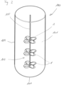
- figure 2 shows an embodiment of a reactor having three propellers 1 mounted to the shaft 105.
- the propellers 1 may all have the same distance between each other as shown here or, alternatively, the distance between the propellers 1 may vary.
- the reactor 100 is shown without a lid for closing the reactor. However, particularly if used in for cultivating cells or multicellular microorganisms, it is preferred to close the reactor 100 with a lid to avoid environmental influences, which may have a negative effect on the cultivation.
- FIG. 3 An example of a toroidal propeller with three propeller blades being looped, wherein a tip of a leading propeller blade is curved back into its trailing propeller blade is shown in figure 3 and a propeller with four propeller blades is shown in figure 4 .
- a propeller 1 used in a reactor comprises a hub 3, which is connected to a shaft 105. Connected to the hub 3 are propeller blades 5. In the embodiments shown here, the propeller comprises three or four propeller blades 5, respectively. However, depending on the size of the propeller, the intended rotation velocity or the substances to be mixed the propeller may comprise any other number of propeller blades 5, for example two propeller blades 5, five or six or even more propeller blades 5.
- Each propeller blade 5 has a curved shape and may have any suitable cross sectional shape.
- the tip 7 of each propeller blade 5 is curved back into its trailing propeller blade 5 thereby forming a curved frame 9.
- the connection of the tip 7 of the propeller blade 5 into its trailing propeller blade may be at any position between the hub and an outer end 11 of the curved frame 9.
- the tip of one propeller blade 5 contacts the trailing propeller blade 5 close to the hub as shown here.
- the propeller 1 is connected to a shaft 105 which can be rotated by a drive. Besides connecting only one propeller 1 to the shaft 105 as shown in figure 1 or three propellers 1 as shown in figure 2 , it is also possible to connect two propellers 1 or even more than three propellers 1 to the shaft. If at least two propellers are connected to the shaft, it is possible to connect all propellers 1 in the same orientation so that a co-directed flow is achieved. Alternatively, at least one propeller 1 may be connected to the shaft in opposite orientation which means that at least one propeller 1 is connected to the shaft upside down compared to at least one further propeller 1 on the shaft.
- each stirrer comprising a shaft to which at least one propeller 1 is connected.
- the propellers 1 on the different shafts may have the same orientation or may be mounted partly in one orientation and partly in the opposite orientation.
- providing more than one stirrer also allows for arranging the stirrers at any angle in the reactor.
- the curved frames 9 formed by the propeller blades 5 may be arranged at an angle of 0° as shown in figures 1 , 3 and 4 , or at an angle larger than 0° as shown in figure 2 .
- an angle of 0° corresponds to an arrangement where the curved frames 9 are oriented perpendicular to the shaft 105.
Landscapes
- Chemical & Material Sciences (AREA)
- Chemical Kinetics & Catalysis (AREA)
- Engineering & Computer Science (AREA)
- Aviation & Aerospace Engineering (AREA)
- Apparatus Associated With Microorganisms And Enzymes (AREA)
Priority Applications (1)
| Application Number | Priority Date | Filing Date | Title |
|---|---|---|---|
| EP23189697.8A EP4501443A1 (de) | 2023-08-04 | 2023-08-04 | Reaktor zur durchführung chemischer oder biologischer prozesse, verfahren unter verwendung des reaktors und verfahren zur herstellung eines rührers |
Applications Claiming Priority (1)
| Application Number | Priority Date | Filing Date | Title |
|---|---|---|---|
| EP23189697.8A EP4501443A1 (de) | 2023-08-04 | 2023-08-04 | Reaktor zur durchführung chemischer oder biologischer prozesse, verfahren unter verwendung des reaktors und verfahren zur herstellung eines rührers |
Publications (1)
| Publication Number | Publication Date |
|---|---|
| EP4501443A1 true EP4501443A1 (de) | 2025-02-05 |
Family
ID=87557470
Family Applications (1)
| Application Number | Title | Priority Date | Filing Date |
|---|---|---|---|
| EP23189697.8A Withdrawn EP4501443A1 (de) | 2023-08-04 | 2023-08-04 | Reaktor zur durchführung chemischer oder biologischer prozesse, verfahren unter verwendung des reaktors und verfahren zur herstellung eines rührers |
Country Status (1)
| Country | Link |
|---|---|
| EP (1) | EP4501443A1 (de) |
Cited By (1)
| Publication number | Priority date | Publication date | Assignee | Title |
|---|---|---|---|---|
| WO2025212666A1 (en) * | 2024-04-03 | 2025-10-09 | Massachusetts Institute Of Technology | Programmable microfluidic devices and methods of making and using thereof |
Citations (7)
| Publication number | Priority date | Publication date | Assignee | Title |
|---|---|---|---|---|
| EP1365106A1 (de) * | 2001-01-26 | 2003-11-26 | Y & Y Co., Ltd. | Strömungsmaschine |
| WO2007111677A2 (en) | 2005-10-26 | 2007-10-04 | Pbs Biotech, Inc | Pneumatic bioreactor |
| US20080268530A1 (en) | 2007-04-24 | 2008-10-30 | Zeikus J Gregory | Pneumatic Bioreactor |
| WO2008133845A2 (en) | 2007-04-23 | 2008-11-06 | Pbs Biotech, Inc. | Pneumatic bioreactor |
| US20080305232A1 (en) * | 2005-04-05 | 2008-12-11 | Gerard Fisson | Device for continuously mixing a food dough provided with two types of superimposed mixing tools and a side discharge |
| WO2010135377A1 (en) | 2009-05-20 | 2010-11-25 | Xyleco, Inc. | Bioprocessing |
| US10836466B2 (en) | 2017-11-06 | 2020-11-17 | Massachusetts Institute Of Technology | Toroidal propeller |
-
2023
- 2023-08-04 EP EP23189697.8A patent/EP4501443A1/de not_active Withdrawn
Patent Citations (8)
| Publication number | Priority date | Publication date | Assignee | Title |
|---|---|---|---|---|
| EP1365106A1 (de) * | 2001-01-26 | 2003-11-26 | Y & Y Co., Ltd. | Strömungsmaschine |
| US20080305232A1 (en) * | 2005-04-05 | 2008-12-11 | Gerard Fisson | Device for continuously mixing a food dough provided with two types of superimposed mixing tools and a side discharge |
| WO2007111677A2 (en) | 2005-10-26 | 2007-10-04 | Pbs Biotech, Inc | Pneumatic bioreactor |
| WO2008133845A2 (en) | 2007-04-23 | 2008-11-06 | Pbs Biotech, Inc. | Pneumatic bioreactor |
| US20080268530A1 (en) | 2007-04-24 | 2008-10-30 | Zeikus J Gregory | Pneumatic Bioreactor |
| WO2010135377A1 (en) | 2009-05-20 | 2010-11-25 | Xyleco, Inc. | Bioprocessing |
| US8669099B2 (en) | 2009-05-20 | 2014-03-11 | Xyleco, Inc. | Bioprocessing |
| US10836466B2 (en) | 2017-11-06 | 2020-11-17 | Massachusetts Institute Of Technology | Toroidal propeller |
Cited By (1)
| Publication number | Priority date | Publication date | Assignee | Title |
|---|---|---|---|---|
| WO2025212666A1 (en) * | 2024-04-03 | 2025-10-09 | Massachusetts Institute Of Technology | Programmable microfluidic devices and methods of making and using thereof |
Similar Documents
| Publication | Publication Date | Title |
|---|---|---|
| EP1773976B2 (de) | Einwegbioreaktorsysteme und -verfahren | |
| US4839046A (en) | Bio-reactor chamber | |
| EP2746382A1 (de) | Wirbelbioreaktor | |
| Chandrashekhar et al. | An overview of fermenter and the design considerations to enhance its productivity | |
| Wang et al. | A novel centrifugal impeller bioreactor. I. Fluid circulation, mixing, and liquid velocity profiles | |
| EP2853584A1 (de) | Einweg-Bioreaktor mit Blende und Verfahren zur Herstellung und zum Betrieb davon | |
| US20210324317A1 (en) | Lid configuration for a bioreactor | |
| US4840905A (en) | Process for culturing biological material | |
| RU2135579C1 (ru) | Аппарат для суспензионного культивирования клеток тканей и микроорганизмов | |
| Chisti et al. | Bioreactor design | |
| Regonesi | Bioreactors: A complete review | |
| JPS5898083A (ja) | 低粘性流動媒体及び高粘性流動媒体取扱用装置 | |
| US12152226B2 (en) | Cell culture bottle | |
| CN222961416U (zh) | 半固态发酵生物反应器 | |
| CN106281979B (zh) | 高效立式发酵罐 | |
| EP4410944A1 (de) | Reaktor zur kultivierung von zellen oder multizellulären mikroorganismen | |
| RU2355751C1 (ru) | Вихревой реактор для проведения биотехнологических процессов в условиях микрогравитации | |
| CN206219581U (zh) | 一种发酵罐 | |
| JP2004261659A (ja) | 混合装置 | |
| CN214361440U (zh) | 一种不锈钢细胞培养罐 | |
| CN105695313B (zh) | 一种正位移输送管式光生物反应器 | |
| JP7827815B2 (ja) | 振とう培養装置および振とう培養方法 | |
| US20260117159A1 (en) | Cell Suspension Culture Device Provided With Flow Diverter | |
| CN224047350U (zh) | 一种用于微生物培养和固碳的螺旋搅拌式生物反应器 | |
| CN224243060U (zh) | 一种鲜花酵素的发酵设备 |
Legal Events
| Date | Code | Title | Description |
|---|---|---|---|
| PUAI | Public reference made under article 153(3) epc to a published international application that has entered the european phase |
Free format text: ORIGINAL CODE: 0009012 |
|
| STAA | Information on the status of an ep patent application or granted ep patent |
Free format text: STATUS: THE APPLICATION HAS BEEN PUBLISHED |
|
| AK | Designated contracting states |
Kind code of ref document: A1 Designated state(s): AL AT BE BG CH CY CZ DE DK EE ES FI FR GB GR HR HU IE IS IT LI LT LU LV MC ME MK MT NL NO PL PT RO RS SE SI SK SM TR |
|
| STAA | Information on the status of an ep patent application or granted ep patent |
Free format text: STATUS: THE APPLICATION IS DEEMED TO BE WITHDRAWN |
|
| 18D | Application deemed to be withdrawn |
Effective date: 20250806 |