EP4501445A1 - Dispositif pour déterminer les paramètres de réaction optimaux de réactions photochimiques dans des échantillons photoréactifs et procédé pour faire fonctionner le dispositif - Google Patents
Dispositif pour déterminer les paramètres de réaction optimaux de réactions photochimiques dans des échantillons photoréactifs et procédé pour faire fonctionner le dispositif Download PDFInfo
- Publication number
- EP4501445A1 EP4501445A1 EP23189794.3A EP23189794A EP4501445A1 EP 4501445 A1 EP4501445 A1 EP 4501445A1 EP 23189794 A EP23189794 A EP 23189794A EP 4501445 A1 EP4501445 A1 EP 4501445A1
- Authority
- EP
- European Patent Office
- Prior art keywords
- light
- emitting semiconductor
- temperature
- receiving container
- semiconductor components
- Prior art date
- Legal status (The legal status is an assumption and is not a legal conclusion. Google has not performed a legal analysis and makes no representation as to the accuracy of the status listed.)
- Withdrawn
Links
Images


Classifications
-
- B—PERFORMING OPERATIONS; TRANSPORTING
- B01—PHYSICAL OR CHEMICAL PROCESSES OR APPARATUS IN GENERAL
- B01J—CHEMICAL OR PHYSICAL PROCESSES, e.g. CATALYSIS OR COLLOID CHEMISTRY; THEIR RELEVANT APPARATUS
- B01J19/00—Chemical, physical or physico-chemical processes in general; Their relevant apparatus
- B01J19/08—Processes employing the direct application of electric or wave energy, or particle radiation; Apparatus therefor
- B01J19/12—Processes employing the direct application of electric or wave energy, or particle radiation; Apparatus therefor employing electromagnetic waves
- B01J19/122—Incoherent waves
-
- B—PERFORMING OPERATIONS; TRANSPORTING
- B01—PHYSICAL OR CHEMICAL PROCESSES OR APPARATUS IN GENERAL
- B01J—CHEMICAL OR PHYSICAL PROCESSES, e.g. CATALYSIS OR COLLOID CHEMISTRY; THEIR RELEVANT APPARATUS
- B01J19/00—Chemical, physical or physico-chemical processes in general; Their relevant apparatus
- B01J19/08—Processes employing the direct application of electric or wave energy, or particle radiation; Apparatus therefor
- B01J19/12—Processes employing the direct application of electric or wave energy, or particle radiation; Apparatus therefor employing electromagnetic waves
- B01J19/122—Incoherent waves
- B01J19/123—Ultraviolet light
-
- B—PERFORMING OPERATIONS; TRANSPORTING
- B01—PHYSICAL OR CHEMICAL PROCESSES OR APPARATUS IN GENERAL
- B01J—CHEMICAL OR PHYSICAL PROCESSES, e.g. CATALYSIS OR COLLOID CHEMISTRY; THEIR RELEVANT APPARATUS
- B01J19/00—Chemical, physical or physico-chemical processes in general; Their relevant apparatus
- B01J19/08—Processes employing the direct application of electric or wave energy, or particle radiation; Apparatus therefor
- B01J19/12—Processes employing the direct application of electric or wave energy, or particle radiation; Apparatus therefor employing electromagnetic waves
- B01J19/122—Incoherent waves
- B01J19/127—Sunlight; Visible light
-
- B—PERFORMING OPERATIONS; TRANSPORTING
- B01—PHYSICAL OR CHEMICAL PROCESSES OR APPARATUS IN GENERAL
- B01J—CHEMICAL OR PHYSICAL PROCESSES, e.g. CATALYSIS OR COLLOID CHEMISTRY; THEIR RELEVANT APPARATUS
- B01J19/00—Chemical, physical or physico-chemical processes in general; Their relevant apparatus
- B01J19/08—Processes employing the direct application of electric or wave energy, or particle radiation; Apparatus therefor
- B01J19/12—Processes employing the direct application of electric or wave energy, or particle radiation; Apparatus therefor employing electromagnetic waves
- B01J19/122—Incoherent waves
- B01J19/128—Infrared light
Definitions
- the invention relates to a device for determining optimal reaction parameters of photochemical reactions in photoreactive substance samples and a method for operating the device.
- the device according to the invention for determining optimal reaction parameters of photochemical reactions in photoreactive substance samples has, according to a first embodiment, a receiving container with a holder device which has an arrangement of receiving openings for cuvettes. And it has a first temperature control device, which is designed to temper the cuvettes, which are arranged in the receiving openings of the receiving container when carrying out an analysis, to a predetermined first temperature.
- the device also has a light module with an arrangement of light-emitting semiconductor components. This arrangement is designed and intended to irradiate the cuvettes.
- each receiving opening from the arrangement of receiving openings corresponds to one of the light-emitting semiconductor components from the arrangement of light-emitting semiconductor components, so that light emitted by each light-emitting semiconductor component passes through the corresponding receiving opening.
- Photoreactive is intended to include all chemical reactions induced or assisted by photons, i.e. not only the actual photochemical reactions in which molecules enter an excited state by absorbing photons, which triggers a chemical reaction, but also catalytic photoreactions, photoinduced and photoassisted catalytic reactions.
- Cuvettes are understood to mean any type of vial or bottle that is suitable for holding photoreactive substances and usually has a capacity in the range of 0.5 ml to 10 ml, but can also be larger or smaller.
- the cuvettes are made of a material that is transparent to the wavelengths of the radiation emitted by the light module.
- Light-emitting semiconductor devices can be all types of LEDs (light emitting diodes) or other devices that are capable of emitting light with wavelengths in a range from ultraviolet to infrared. LEDs here means all such "LEDs”.
- the "first temperature” corresponds to the temperature that the substance sample in the cuvette should have when the device is operating during screening.
- the “second temperature” corresponds to an operating temperature intended for the diodes, hereinafter referred to as the diode temperature, which is usually different from the first temperature.
- the first and second temperatures can be in a predetermined range with corresponding tolerance limits.
- the temperature range for the first temperature depends on the photochemical reaction being investigated, or on the chemical reactions that are induced or assisted by photons, since the actual photochemical reaction, in which molecules enter an excited state by absorbing photons, is almost temperature-independent.
- the temperature range for the second temperature or diode temperature extends from 0 °C to +60 °C, possibly up to +80 °C, but is preferably +20 °C to +40 °C in order to avoid temperature-dependent changes in the performance of the diodes.
- the device according to the invention can be used to control the temperature of the cuvettes using the two temperature control devices without the LEDs being affected by condensation, icing or overheating.
- the control unit can provide for the second temperature control device to be controlled depending on the substance sample temperature in such a way that the diode temperature is kept at its predetermined value.
- the device according to the invention can be used to carry out basic photochemical investigations for research and development in industry and science in a material-saving and cost-effective manner because several irradiation experiments can be carried out in parallel and simultaneously with very small sample quantities, with the LEDs being thermally decoupled from the receiving container with the cuvettes using the second temperature control device. This advantageously prevents or reduces a temperature drift of the light-emitting semiconductor elements that occurs during continuous operation, advantageously to a maximum of 0.6 °C, which would otherwise lead to a change or reduction in the light intensity and thus to an impairment of accurate measurements.
- the light module has at least one fluid line for the flow of a tempering fluid, which is guided in a tempering circuit that provides the second tempering device.
- the fluid line can be a tempering channel, a hose or even a pipe.
- the fluid lines mentioned can be integrated in the housing or can be partially laid in it as components separate from the housing. This allows the tempering fluid to flow through the light module and creates direct tempering.
- the light module is connected on its side facing away from the receiving container to a cooling plate which provides the second temperature control device.
- the light module has at least one thermal interface made of one or more thermally conductive materials between the light-emitting semiconductor components and the cooling plate.
- the cooling plate can also be designed with a temperature control channel for the flow of a temperature control fluid.
- the light module delimits an emission space in which the arrangement of the LEDs is arranged, and has at least one opening which is optically connected to the emission space and which faces the receiving container, the opening being sealed by a pane which is transparent to the light from the LEDs, the LEDs being arranged on a surface of the emission space which is opposite the transparent pane.
- the housing can have its own assigned opening for each light-emitting semiconductor component, which is each closed by a transparent pane, the arrangement of the openings corresponding to the arrangement of the LEDs.
- the emission space is connected to the at least one fluid line or the temperature control channel for the flow of the temperature control fluid, the light-emitting semiconductor components being in direct contact with the temperature control fluid.
- An electrically non-conductive temperature control fluid is used for this purpose. This enables a temperature control fluid circuit for direct temperature control.
- the "optical connection" of the emission space with the at least one opening is to be understood as meaning that there is either direct “visual contact” between the LEDs in the emission space and the openings, or that the light module has optical steering or guiding elements, e.g. optical fibers, through which the light emitted by the LEDs reaches the openings.
- the first temperature control device of the receiving container is at least one temperature control element arranged in the receiving container.
- This temperature control element can be a heating and/or cooling element that is in heat-conducting contact with the cuvettes by means of a thermal interface such as a temperature control bath.
- the first temperature control device can have a separate heat source or heat sink that forms a temperature control circuit with a circulating temperature control fluid with the receiving container, so that the cuvettes in the receiving container are located, for example, in a flowing temperature control bath.
- the first temperature control device is designed to temperature the cuvettes in the receiving openings of the receiving container to the predetermined first or substance sample temperature, which is in a temperature range from -25 °C to +180 °C, preferably in a temperature range from -20 °C to +150 °C.
- the cuvettes can be tempered to an optimal reaction temperature without having to take the diode temperature into account, since the thermal decoupling achieved by the second tempering device prevents the LEDs from being affected by condensation, icing or overtemperature.
- the device according to the invention can provide that the receiving container is arranged above the light module.
- the cuvettes can thus be irradiated from below and are easily accessible from above for inserting and removing the cuvettes into the corresponding receiving openings, or for taking samples during the reaction.
- the light module can also be arranged above the receiving container.
- This alternative offers the possibility of arranging, for example, a stirring plate device under the receiving container so that a magnetic stirrer can be used in each cuvette in order to stir the substance sample present there.
- a thermally insulating separating plate can be provided between the receiving container and the light module in order to support the thermal decoupling of the receiving container and the light module.
- the separating plate can be made of transparent material or have passage openings, the arrangement of which which corresponds to the LEDs or the receiving openings and which can be closed with a transparent pane.
- the semiconductor components emit light with wavelengths in a range from 250 nm to 650 nm, i.e. from the ultraviolet to the visible "red" range. At least two light-emitting semiconductor components emit light of the same wavelength, so that in one case all light-emitting semiconductor components emit light of the same wavelength. Alternatively, it can also be provided that each light-emitting semiconductor component emits light of a different wavelength. In this way, the cuvettes can advantageously be irradiated with the desired wavelength. Test irradiations with different wavelengths are also possible.
- each light-emitting semiconductor component can be adjusted by the control unit.
- the intensity of each wavelength of two or more light-emitting semiconductor components can be coordinated with one another using the control unit, so that the irradiation intensity can be adjusted even if the LEDs have different efficiencies depending on the wavelength.
- the efficiency describes the ratio of the radiant power to the power consumed and currently varies between 10% (green, 530 to 540 nm), 20% (blue, 440 nm) and 70% (red, from 650 nm) depending on the wavelength.
- the efficiency of LEDs in the UV wavelength range is currently a maximum of 10%.
- the invention is not limited to LEDs with the efficiencies mentioned, since constant further developments in this field lead to higher efficiencies, so that a device according to the invention can of course also have LEDs with higher efficiencies developed in the future.
- the power consumption By controlling the power consumption, the irradiation intensity of the LEDs of different wavelengths can be adjusted.
- the control unit also allows each light-emitting semiconductor component to be controlled individually via a touch panel on the control unit and its intensity or light output to be adjusted, for example dimmed. In addition, all light-emitting semiconductor components can be controlled simultaneously.
- the light module has a housing and a cassette in which the arrangement of light-emitting semiconductor components.
- the cassette is detachably arranged in the housing and can have a handle. This cassette makes it easy to exchange different arrangements of light-emitting semiconductor components.
- the second temperature control device which thermally decouples the LEDs from the cuvettes, making it easier to maintain the predetermined second or diode temperature, can be integrated into such a cassette or into the housing of the light module as a boundary of the receiving opening for the cassette or the cassette compartment.
- the second temperature control device is intended for the direct temperature control of the light-emitting semiconductor elements, it will in any case be integrated in the cassette, which then has corresponding connections for connecting the fluid lines to the temperature control circuit.
- this cassette has at least one fluid channel that is connected to the emission space in which the arrangement of the light-emitting semiconductor components is arranged.
- a connection of the light-emitting semiconductor components to a connection element on the housing can be provided by a detachable plug connection between the cassette and the housing.
- a second temperature control device for indirect temperature control can optionally be formed in the cassette or in the housing of the light module adjacent to the cassette compartment.
- the device according to the invention can therefore have several arrangements of light-emitting semiconductor elements or several cassettes, each with an arrangement of light-emitting semiconductor elements, which can be used alternately in the light module.
- a cassette can have light-emitting semiconductor components, all of which emit light or radiation of the same wavelength, and in another cassette (replacement cassette) each light-emitting semiconductor component can emit a different wavelength.
- the arrangement of light-emitting semiconductor components can, for example, have one by three, i.e. three, or five by five, i.e. 25, or three by three, i.e. nine, light-emitting semiconductor components, which can emit light or radiation with nine different wavelengths simultaneously when the exchange cassette is used.
- the receiving container and the light module each have at least one temperature sensor that is operatively coupled to the control unit, which is also connected to the first temperature control device of the receiving container.
- the temperature sensors make it possible to monitor, control and ultimately regulate the temperature control devices.
- the device according to the invention has a vibrating plate on which the receiving container and the light module are arranged and which can be operated with the control unit.
- the vibrating plate is part of a vibrating device.
- the arrangement of receiving container and light module can be vibrated in an oscillating manner by the control unit for a predetermined time and frequency using the vibrating plate. Depending on the substance to be tested, this enables good mixing and even irradiation of the substance samples, especially with viscous substances and substances that tend to phase separation.
- the oscillating movement of the vibrating plate prevents undesirable shear forces on the substance.
- the receiving container has a lid that is at least partially closed.
- a completely closed lid is useful, for example, to prevent the escape of tempering fluid when the vibrating plate is activated.
- a completely closed lid offers protection against escaping radiation emitted by the light-emitting semiconductor components that passes through the cuvettes without absorption, especially in the arrangement in which the receiving container sits on the light module.
- the lid can also have through-openings for easy sampling from the cuvettes.
- the invention further relates to a method for operating a device for determining optimal reaction parameters of a photochemical reaction in photoreactive substance samples using a device according to the invention.
- This has at least one receiving container with a holder device that contains an arrangement of receiving openings for cuvettes.
- the receiving container also has a first temperature control device that is designed to control the temperature of the cuvettes that can be arranged in the receiving openings of the receiving container to a predetermined first temperature.
- the device also has a light module with an arrangement of light-emitting Semiconductor components which are designed to irradiate the cuvettes which can be arranged in the receiving openings of the receiving container, and it has a second tempering device for tempering the LEDs to a predetermined second temperature.
- it has a control unit for the LEDs which is connected at least to the second tempering device.
- the light-emitting semiconductor components can be LEDs.
- the two temperature control devices allow precise temperature control of the cuvettes between -25 °C and +180 °C, preferably between -20 °C and +150 °C, without affecting the function or performance of the light-emitting semiconductor components such as LEDs, and thus correct measurement results.
- several samples can be tested simultaneously. For example, one reaction parameter can be varied at a time, but the other conditions can be kept the same for all samples. For example, several substance samples of the same composition can be irradiated with a different wavelength in one experiment.
- the control unit controls the LEDs which emit radiation of different wavelengths in the range from 250 nm to 650 nm in such a way that by adjusting the input power the LEDs are set to the same irradiation intensity depending on a wavelength-dependent efficiency.
- the method according to the invention provides that the vibration frequency and vibration duration of the vibrating plate are also controlled by means of the control unit.
- the vibrating plate can be shaken in an oscillating manner.
- the method according to the invention advantageously makes it possible to determine the optimal wavelength for a defined reaction process of the photoreactive substance to be examined by first inserting a cassette with the arrangement of LEDs with different wavelengths in the light module. In a subsequent step, the cassette used first with the arrangement of LEDs with different wavelengths can then be exchanged for a cassette with light-emitting semiconductor components that all emit radiation of the same wavelength, so that further investigations such as concentration determinations can be carried out.
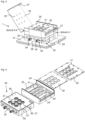
- the device 1 according to the invention for optimizing reaction parameters of a photochemical reaction or improving photochemical reactions in photoreactive substance samples shows a receiving container 20 and a light module 30.
- a plate 22 is mounted in the receiving container 20 as a holder device, which has nine receiving openings 21. These receiving openings 21 are arranged equidistantly from one another in three by three pieces and are designed in such a way that they can hold cuvettes 4 into which photoreactive substance samples can be filled.
- the receiving container 20 from Fig. 1 has a lid 23 which can be opened for arranging and removing the cuvettes 4 in the receiving openings 21 - it is also shown in the opened position and can be closed to protect the cuvettes 4.
- the surface of the cover 23 is completely closed.
- the lid 23 has through openings 23' above the cuvettes 4, which are aligned with the receiving openings 21 when the lid 23 is closed, so that the contents of the cuvettes 4 can be reached, for example, with a pipette.
- the light module 30 is arranged below the receiving container 20 and is firmly connected to the receiving container 20, which has a transparent bottom or passage openings arranged corresponding to the receiving openings 21, which are closed with transparent panes.
- the light module 30 has a housing 33, which is mounted on a vibrating plate 51 of a vibrating device 50, here via angle plates 53 by means of Screws, is firmly mounted.
- the vibrating device 50 also has a control device 52 with which the frequency and duration of the oscillation of the vibrating plate 51 can be controlled.
- the frequency should not be chosen to be too high; frequencies of up to a maximum of 600 rpm have proven to be suitable for a circularly vibrating platform shaker as the vibrating device 50.
- the light module 30 here has a cassette 32 which is detachably connected to the housing 33 and can thus be pulled out.
- Fig. 1 shows an additional bow-shaped handle 38 provided on the cassette 32.
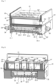
- a board or plate 39 with an arrangement of LEDs 31 is arranged, the light of which hits the plate 22 with the inserted cuvettes 4 from below.
- the light of the LEDs 31 is in Fig. 2 with curved arrows.
- the housing 33 of the light module 30 has in the Fig. 2 In the example shown, the housing 33 has a large opening 36' towards the receiving container 20 for the passage of light.
- the opening 36' is covered with a disc 37 that is transparent to the radiation from the LEDs 31.
- a separating plate preferably made of thermally insulating material, can be arranged between the receiving container 20 and the light module 30, which closes off the housing 33 of the light module 30 at the top and at the same time forms the bottom of the receiving container 20 and is either designed as a transparent disc 37 or has passage openings that are arranged corresponding to the LEDs 31 or the receiving openings 21 and are closed with transparent discs 37.
- the cassette 32 can be fitted with a glass or a transparent panel for the radiation of the LEDs 31 - in Fig. 2 not shown - so that the cassette 32 forms a closed element and the light-emitting semiconductor components 31 are protected from dirt.
- the light module 30 or the cassette 32 can be Fig. 3 to 10
- each light-emitting semiconductor element has an associated passage opening with a correspondingly transparent pane.
- the receiving container 20 has a first temperature control device with which the interior of the receiving container 20 or the plate 22 or the cuvettes 4 can be tempered in a temperature range from -25 °C to +180 °C, for example -20 °C to +80 °C. can.
- the first temperature control device is designed as a temperature control bath and is schematically shown with supply and discharge lines 24 for a temperature control fluid to an external heating or cooling source 25.
- the temperature control fluid flows around the cuvettes 4 in the temperature control bath.
- care must be taken to ensure that the temperature control fluid is sufficiently transparent for the wavelengths of the light-emitting semiconductor elements 31 used in the light module 30.
- the receiving container 20 has a temperature sensor 61, which can be arranged, for example, on an inner wall of the receiving container 20 or on the plate 22 adjacent to the receiving openings 21.
- the light module 20 also has a second temperature control device with which the cassette 32 and thus the LEDs 31 can be tempered, i.e. cooled or heated, during operation.
- the second tempering device is also designed as a tempering bath and is schematically shown with supply and discharge lines 34 for a further tempering fluid to an external cooling or heating source 35.
- the tempering fluid of the second tempering device can differ from the tempering fluid of the first tempering device, especially if the second tempering device is designed for direct tempering of the light-emitting semiconductor elements.
- the tempering fluid of the second tempering device particular attention should be paid to ensuring that the tempering fluid is not only transparent to the wavelengths of the light-emitting semiconductor elements used in the light module, but is also electrically non-conductive.
- the second tempering device also has a temperature sensor 62 for detecting a diode temperature, which is arranged on the circuit board 39.
- a tempering channel 34' is formed in the housing 33 or the cassette 32 for the flow of a tempering fluid, which is guided in a tempering circuit with the supply and discharge lines 34.
- the device 1 has a control unit 10, which is external here, but can also - not shown figuratively - be mounted in the device 10 and connected to the essential components that it is intended to control, namely the light-emitting semiconductor elements 31, the first and second temperature control device and the vibrating device 50 or its control device 52 can be operatively coupled.
- the electrical and electronic connections required for this are not shown specifically for the sake of simplicity and are represented by the connecting line 11.
- the control unit 10 makes it possible to control the light-emitting semiconductor components 31 individually and to adjust the light intensity of each light-emitting semiconductor component 31 independently of one another.
- the control unit 10 is further designed to control both the first and the second temperature control device. It is provided that the first temperature control device controls the interior of the receiving container 20 to a substance sample temperature in a range from -25 °C to +180 °C and, depending on the substance sample temperature reached in the receiving container 20, the second temperature control device of the light module 30 is controlled in such a way that the temperature of the light-emitting semiconductor elements 31 remains consistently below a predetermined limit temperature, the so-called diode temperature, which ideally remains in a range from +20 °C to +30 °C or up to +40 °C.
- the intensity of the light-emitting semiconductor components 31 of each wavelength can be coordinated with one another using the control unit 10, so that the irradiation intensity can be adjusted even with the different efficiencies of the LEDs 31 depending on the wavelength.
- the power consumption of the individual LEDs 31 is controlled depending on their efficiency in order to adapt the radiation power of the LEDs 31 to one another.
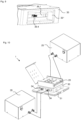
- Figures 3 to 10 show an alternative embodiment of the device 1, in which the receiving container 20 consists of a heat-conducting material block with a molded-in tempering channel 24", which extends meanderingly between two connection openings 24' and provides the first tempering device. Between the turns of the tempering channel 24", there are three times three continuous receiving openings in the receiving container 20 21' is designed as a holder device for receiving the cuvettes. By arranging a plate 22, the temperature control channel 24" is closed at the top, the plate 22 having three times three receiving openings 21 which, when arranged on the receiving container 20, are aligned with its receiving openings 21'.
- the receiving container 20 can, for example, be made from a metal block, e.g.
- the temperature control channel 24" serves to conduct a temperature control medium in order to exchange heat via the metal wall of the receiving container 20 with the cuvettes received in the receiving openings 21' or the substance samples contained therein, i.e. to supply or dissipate it.
- a safety switch 27 is also arranged on the receiving container 20, which contacts a switch 27' when the lid 23 is closed in order to ensure that the device 1 can only be operated when the lid 23 is correctly closed.
- the receiving container 20 is arranged on the light module 30.
- the housing 33 of the light module 30 is closed off with a separating or insulating plate 36, which consists of thermally insulating material.
- the insulating plate 36 has three times three through-openings 36' corresponding to the arrangement of the receiving openings 21, 21'.
- each through-opening 36' is designed as a through-bore for receiving a fiber optic 31' made of optical fibers.
- the through-opening 36' is widened to form a receptacle in which a transparent disk 37 made of glass or quartz is inserted in a sealed manner by means of an O-ring 37', wherein Fig. 4 and 8 only one disk 37 is shown as an example.
- the fiber optics 31' can be used to introduce the photons of the respective LED 31 from the cassette 32 into a cuvette 4, which is received in the receiving opening 21, 21' and stands on the disk 37.
- Fig. 5 and 6 show the cassette 32 of the exemplary device 1 from Fig. 3 to 10
- the cassette 32 has a cassette housing 32.1 and a cassette cover 32.2 that closes the cassette housing 32.1.
- the cassette 32 is designed to be accommodated in a correspondingly designed compartment in the housing 33 of the light module 30, so that the front side of the cassette 32, on which the handle 38, designed here as a ball knob, and the connections 34 of the second temperature control device are located, is flush with the front side of the housing 33 of the light module 30.
- the cassette housing 32.1 and the cassette cover 32.2 delimit an emission space in which a circuit board 39 with the three times three LEDs 31 is arranged.
- a respective temperature control channel 34' which is designed in the cassette housing 32.2 here as an inlet or outlet opening, connects the connections 34 with the emission space, so that a temperature control fluid for controlling the temperature of the LEDs 31 can be passed through the cassette 32.
- the compartment which is designed in the housing 33 of the light module 30 for receiving the cassette 32 is, as in Fig. 7 and 8 as can be seen, open at the bottom so that additional heat absorbed by the cassette housing 32.1 can be dissipated into the environment, wherein the cassette housing 32.1 is formed with ribs 32' on the underside for better heat dissipation.
- a fiber optic 31' made of optical fibers In the cassette cover 32.2, three times three through-openings 32.3 are formed in accordance with the arrangement of the LEDs 31, through each of which a fiber optic 31' made of optical fibers also extends.
- the fiber optics 31' in the through-openings 32.3 of the cassette cover 32.2 and in the through-openings 36' of the insulator plate 36 are in contact.
- a fiber optic 31' made of optical fibers can extend continuously through the through-opening 32.3 in the cassette cover 32.2 and through the through-opening 36' in the insulator plate 36.
- the cassette cover 32.2 rests against a transparent pane 32.4, which is inserted into the cassette housing 32.1 at a distance from the circuit board 39 with the LEDs 31 and is sealed by means of a circumferential seal 32.6.
- a spacer plate 32.5 arranged on the circuit board 39 has through-openings for receiving the LEDs 31 in order to limit the beam angle of the emitted radiation, so that the emitted radiation of each LED 31 hits the fiber optic 31' in the respectively assigned through-opening 32.3.
- the electrical connection of the board 39 with the LEDs 31 is made from the back of the light module 30, ie the side facing away from the handle 38 and the connections 34.
- the cassette 32 is designed with a type of plug on the back, which Arrangement of the cassette 32 in the compartment provided for this purpose in the light module 30 engages with a suitable socket which is correspondingly arranged in the compartment.
- the housing 33 of the light module 30 has a cover plate 33' on the back, which closes a connection chamber 33" formed in the housing 33.
- the connection chamber 33" has an opening to the cassette compartment on the inner wall.
- a connection element 39' provided on the cover plate 33' allows the connection of a socket board 39.2 via a terminal block 39.3, which is arranged with the terminal block 39.3 in the connection chamber 33".
- the socket board 39.2 is arranged on the inner wall of the connection chamber 33" so as to close the opening.
- the pin socket of a pin plug connection 39.4 extends from the socket board 39.2 through the opening in the inner wall of the connection chamber 33", as in Fig.
- the pin plug of the pin plug connection 39.4 is connected to a plug board 39.1 which is attached from the outside to the rear of the cassette 32 or the cassette housing 32.1.
- the board 39 is connected to the plug board 39 via a printed circuit board connector (not shown), the printed circuit board connector extending through an opening which is formed in the rear wall of the cassette housing 32.1 and is closed in a liquid-tight manner by the plug board 39.
Landscapes
- Chemical & Material Sciences (AREA)
- Physics & Mathematics (AREA)
- Electromagnetism (AREA)
- Health & Medical Sciences (AREA)
- General Health & Medical Sciences (AREA)
- Toxicology (AREA)
- Organic Chemistry (AREA)
- Chemical Kinetics & Catalysis (AREA)
- Optical Measuring Cells (AREA)
Priority Applications (3)
| Application Number | Priority Date | Filing Date | Title |
|---|---|---|---|
| EP23189794.3A EP4501445A1 (fr) | 2023-08-04 | 2023-08-04 | Dispositif pour déterminer les paramètres de réaction optimaux de réactions photochimiques dans des échantillons photoréactifs et procédé pour faire fonctionner le dispositif |
| EP24758713.2A EP4642569A1 (fr) | 2023-08-04 | 2024-08-01 | Appareil de détermination de paramètres de réaction optimaux de réactions photochimiques dans des échantillons de substance photoréactive et procédé de fonctionnement de l'appareil |
| PCT/EP2024/071826 WO2025031931A1 (fr) | 2023-08-04 | 2024-08-01 | Appareil de détermination de paramètres de réaction optimaux de réactions photochimiques dans des échantillons de substance photoréactive et procédé de fonctionnement de l'appareil |
Applications Claiming Priority (1)
| Application Number | Priority Date | Filing Date | Title |
|---|---|---|---|
| EP23189794.3A EP4501445A1 (fr) | 2023-08-04 | 2023-08-04 | Dispositif pour déterminer les paramètres de réaction optimaux de réactions photochimiques dans des échantillons photoréactifs et procédé pour faire fonctionner le dispositif |
Publications (1)
| Publication Number | Publication Date |
|---|---|
| EP4501445A1 true EP4501445A1 (fr) | 2025-02-05 |
Family
ID=87557833
Family Applications (2)
| Application Number | Title | Priority Date | Filing Date |
|---|---|---|---|
| EP23189794.3A Withdrawn EP4501445A1 (fr) | 2023-08-04 | 2023-08-04 | Dispositif pour déterminer les paramètres de réaction optimaux de réactions photochimiques dans des échantillons photoréactifs et procédé pour faire fonctionner le dispositif |
| EP24758713.2A Pending EP4642569A1 (fr) | 2023-08-04 | 2024-08-01 | Appareil de détermination de paramètres de réaction optimaux de réactions photochimiques dans des échantillons de substance photoréactive et procédé de fonctionnement de l'appareil |
Family Applications After (1)
| Application Number | Title | Priority Date | Filing Date |
|---|---|---|---|
| EP24758713.2A Pending EP4642569A1 (fr) | 2023-08-04 | 2024-08-01 | Appareil de détermination de paramètres de réaction optimaux de réactions photochimiques dans des échantillons de substance photoréactive et procédé de fonctionnement de l'appareil |
Country Status (2)
| Country | Link |
|---|---|
| EP (2) | EP4501445A1 (fr) |
| WO (1) | WO2025031931A1 (fr) |
Citations (3)
| Publication number | Priority date | Publication date | Assignee | Title |
|---|---|---|---|---|
| WO2018098189A1 (fr) * | 2016-11-22 | 2018-05-31 | Hepatochem, Inc. | Dispositif de photochimie |
| WO2018220008A1 (fr) * | 2017-05-31 | 2018-12-06 | Fundació Institut Català D'investigació Química (Iciq) | Photoréacteur |
| US20210041472A1 (en) * | 2017-07-14 | 2021-02-11 | Meon Medical Solutions Gmbh & Co Kg | Automatic analyzer and method for carrying out chemical, biochemical, and/or immunochemical analyses |
-
2023
- 2023-08-04 EP EP23189794.3A patent/EP4501445A1/fr not_active Withdrawn
-
2024
- 2024-08-01 WO PCT/EP2024/071826 patent/WO2025031931A1/fr active Pending
- 2024-08-01 EP EP24758713.2A patent/EP4642569A1/fr active Pending
Patent Citations (3)
| Publication number | Priority date | Publication date | Assignee | Title |
|---|---|---|---|---|
| WO2018098189A1 (fr) * | 2016-11-22 | 2018-05-31 | Hepatochem, Inc. | Dispositif de photochimie |
| WO2018220008A1 (fr) * | 2017-05-31 | 2018-12-06 | Fundació Institut Català D'investigació Química (Iciq) | Photoréacteur |
| US20210041472A1 (en) * | 2017-07-14 | 2021-02-11 | Meon Medical Solutions Gmbh & Co Kg | Automatic analyzer and method for carrying out chemical, biochemical, and/or immunochemical analyses |
Also Published As
| Publication number | Publication date |
|---|---|
| WO2025031931A1 (fr) | 2025-02-13 |
| EP4642569A1 (fr) | 2025-11-05 |
Similar Documents
| Publication | Publication Date | Title |
|---|---|---|
| DE69112565T2 (de) | Temperaturgeregeltes gehäuse für einen diagnoseanalysator. | |
| DE60000386T2 (de) | Adapter für eine pipette, pipette zur absorptionsmessung, verfahren und vorrichtung zur absorptionsmessung | |
| EP0938383A1 (fr) | Dispositif pour effectuer des analyses d'echantillons cellulaires ou similaires | |
| DE10259251B4 (de) | Kultivierkammer an einem Mikroskopgestell | |
| WO1995031716A1 (fr) | Lame porte-objet pour microscope | |
| EP1096998B1 (fr) | Procede et dispositif pour preparer des echantillons destines a la detection d'une sequence nucleotidique | |
| WO2008128534A1 (fr) | Cuvette pour l'analyse optique de petits volumes | |
| EP1206969A2 (fr) | Méthode et dispositif pour tempérer des échantillons | |
| DE102008059985B3 (de) | Real-Time-PCR mittels Gigahertz- oder Terahertz-Spektrometrie | |
| DE112018000433T5 (de) | Optisches multi-temperatur-spektrometer-modul, systeme und verfahren zu deren verwendung | |
| DE112009000004B4 (de) | Vorrichtung zur Röntgenfluoreszenzanalyse und deren Verwendung | |
| DE10341500A1 (de) | Mikrophotoreaktor zur Durchführung photochemischer Reaktionen | |
| EP4501445A1 (fr) | Dispositif pour déterminer les paramètres de réaction optimaux de réactions photochimiques dans des échantillons photoréactifs et procédé pour faire fonctionner le dispositif | |
| WO2003019158A2 (fr) | Systeme d'analyse thermo-optique pour reactions biochimiques | |
| AT503448B1 (de) | Gerät zur präparation biologischer proben für die elektronenmikroskopie | |
| DE102019122163A1 (de) | Messanordnung zur Messung des gesamten gebundenen Stickstoffs in einer Messflüssigkeit | |
| DE102006015092A1 (de) | Spektroskopiegestützte Echtzeitsteuerung für mikrowellengestützte Chemie | |
| DE10132761B4 (de) | Klimatisierbare Probenkammer und Verfahren zur Klimatisierung der Umgebung von Proben | |
| DE2651356C2 (fr) | ||
| EP1251946A1 (fr) | Melangeur a force capillaire | |
| DE102008006035B3 (de) | Mikrotechnisches Bauelement zur Untersuchung einer fluidischen Probe und ein Verfahren zu dessen Herstellung | |
| EP3344383B1 (fr) | Dispositif et procédé de stimulation optique d'un échantillon biologique optiquement activable | |
| DE102021131653B3 (de) | Thermozykler und Verfahren zum Betreiben eines Thermozyklers | |
| EP0531373B1 (fr) | Photometre a ecran diffusant, en particulier pour la determination cinetique de proteines totales | |
| WO2025097190A1 (fr) | Analyseur doté d'un dispositif de refroidissement |
Legal Events
| Date | Code | Title | Description |
|---|---|---|---|
| PUAI | Public reference made under article 153(3) epc to a published international application that has entered the european phase |
Free format text: ORIGINAL CODE: 0009012 |
|
| STAA | Information on the status of an ep patent application or granted ep patent |
Free format text: STATUS: THE APPLICATION HAS BEEN PUBLISHED |
|
| AK | Designated contracting states |
Kind code of ref document: A1 Designated state(s): AL AT BE BG CH CY CZ DE DK EE ES FI FR GB GR HR HU IE IS IT LI LT LU LV MC ME MK MT NL NO PL PT RO RS SE SI SK SM TR |
|
| STAA | Information on the status of an ep patent application or granted ep patent |
Free format text: STATUS: THE APPLICATION IS DEEMED TO BE WITHDRAWN |
|
| 18D | Application deemed to be withdrawn |
Effective date: 20250806 |