EP4501505A2 - Machine-outil avec un porte-outil mobile, porte-outil et porte-outil pour cette machine-outil - Google Patents
Machine-outil avec un porte-outil mobile, porte-outil et porte-outil pour cette machine-outil Download PDFInfo
- Publication number
- EP4501505A2 EP4501505A2 EP24220729.8A EP24220729A EP4501505A2 EP 4501505 A2 EP4501505 A2 EP 4501505A2 EP 24220729 A EP24220729 A EP 24220729A EP 4501505 A2 EP4501505 A2 EP 4501505A2
- Authority
- EP
- European Patent Office
- Prior art keywords
- tool
- tool holder
- clamping
- tie rod
- carrier
- Prior art date
- Legal status (The legal status is an assumption and is not a legal conclusion. Google has not performed a legal analysis and makes no representation as to the accuracy of the status listed.)
- Pending
Links
Images


Classifications
-
- B—PERFORMING OPERATIONS; TRANSPORTING
- B23—MACHINE TOOLS; METAL-WORKING NOT OTHERWISE PROVIDED FOR
- B23Q—DETAILS, COMPONENTS, OR ACCESSORIES FOR MACHINE TOOLS, e.g. ARRANGEMENTS FOR COPYING OR CONTROLLING; MACHINE TOOLS IN GENERAL CHARACTERISED BY THE CONSTRUCTION OF PARTICULAR DETAILS OR COMPONENTS; COMBINATIONS OR ASSOCIATIONS OF METAL-WORKING MACHINES, NOT DIRECTED TO A PARTICULAR RESULT
- B23Q3/00—Devices holding, supporting, or positioning work or tools, of a kind normally removable from the machine
- B23Q3/18—Devices holding, supporting, or positioning work or tools, of a kind normally removable from the machine for positioning only
- B23Q3/183—Centering devices
-
- B—PERFORMING OPERATIONS; TRANSPORTING
- B23—MACHINE TOOLS; METAL-WORKING NOT OTHERWISE PROVIDED FOR
- B23B—TURNING; BORING
- B23B29/00—Holders for non-rotary cutting tools; Boring bars or boring heads; Accessories for tool holders
- B23B29/04—Tool holders for a single cutting tool
- B23B29/046—Tool holders for a single cutting tool with an intermediary toolholder
-
- B—PERFORMING OPERATIONS; TRANSPORTING
- B23—MACHINE TOOLS; METAL-WORKING NOT OTHERWISE PROVIDED FOR
- B23B—TURNING; BORING
- B23B29/00—Holders for non-rotary cutting tools; Boring bars or boring heads; Accessories for tool holders
- B23B29/04—Tool holders for a single cutting tool
- B23B29/12—Special arrangements on tool holders
- B23B29/20—Special arrangements on tool holders for placing same by shanks in sleeves of a turret
-
- B—PERFORMING OPERATIONS; TRANSPORTING
- B23—MACHINE TOOLS; METAL-WORKING NOT OTHERWISE PROVIDED FOR
- B23B—TURNING; BORING
- B23B29/00—Holders for non-rotary cutting tools; Boring bars or boring heads; Accessories for tool holders
- B23B29/04—Tool holders for a single cutting tool
- B23B29/12—Special arrangements on tool holders
- B23B29/20—Special arrangements on tool holders for placing same by shanks in sleeves of a turret
- B23B29/205—Special arrangements on tool holders for placing same by shanks in sleeves of a turret the tools being adjustable
-
- B—PERFORMING OPERATIONS; TRANSPORTING
- B23—MACHINE TOOLS; METAL-WORKING NOT OTHERWISE PROVIDED FOR
- B23B—TURNING; BORING
- B23B29/00—Holders for non-rotary cutting tools; Boring bars or boring heads; Accessories for tool holders
- B23B29/24—Tool holders for a plurality of cutting tools, e.g. turrets
- B23B29/242—Turrets, without description of the angular positioning device
-
- B—PERFORMING OPERATIONS; TRANSPORTING
- B23—MACHINE TOOLS; METAL-WORKING NOT OTHERWISE PROVIDED FOR
- B23B—TURNING; BORING
- B23B29/00—Holders for non-rotary cutting tools; Boring bars or boring heads; Accessories for tool holders
- B23B29/24—Tool holders for a plurality of cutting tools, e.g. turrets
- B23B29/244—Toolposts, i.e. clamping quick-change toolholders, without description of the angular positioning device
- B23B29/246—Quick-change tool holders
-
- B—PERFORMING OPERATIONS; TRANSPORTING
- B23—MACHINE TOOLS; METAL-WORKING NOT OTHERWISE PROVIDED FOR
- B23Q—DETAILS, COMPONENTS, OR ACCESSORIES FOR MACHINE TOOLS, e.g. ARRANGEMENTS FOR COPYING OR CONTROLLING; MACHINE TOOLS IN GENERAL CHARACTERISED BY THE CONSTRUCTION OF PARTICULAR DETAILS OR COMPONENTS; COMBINATIONS OR ASSOCIATIONS OF METAL-WORKING MACHINES, NOT DIRECTED TO A PARTICULAR RESULT
- B23Q1/00—Members which are comprised in the general build-up of a form of machine, particularly relatively large fixed members
- B23Q1/70—Stationary or movable members for carrying working-spindles for attachment of tools or work
-
- B—PERFORMING OPERATIONS; TRANSPORTING
- B23—MACHINE TOOLS; METAL-WORKING NOT OTHERWISE PROVIDED FOR
- B23B—TURNING; BORING
- B23B2270/00—Details of turning, boring or drilling machines, processes or tools not otherwise provided for
- B23B2270/06—Use of elastic deformation
-
- B—PERFORMING OPERATIONS; TRANSPORTING
- B23—MACHINE TOOLS; METAL-WORKING NOT OTHERWISE PROVIDED FOR
- B23B—TURNING; BORING
- B23B2270/00—Details of turning, boring or drilling machines, processes or tools not otherwise provided for
- B23B2270/12—Centering of two components relative to one another
-
- B—PERFORMING OPERATIONS; TRANSPORTING
- B23—MACHINE TOOLS; METAL-WORKING NOT OTHERWISE PROVIDED FOR
- B23B—TURNING; BORING
- B23B31/00—Chucks; Expansion mandrels; Adaptations thereof for remote control
- B23B31/02—Chucks
- B23B31/24—Chucks characterised by features relating primarily to remote control of the gripping means
- B23B31/26—Chucks characterised by features relating primarily to remote control of the gripping means using mechanical transmission through the working-spindle
- B23B31/261—Chucks characterised by features relating primarily to remote control of the gripping means using mechanical transmission through the working-spindle clamping the end of the toolholder shank
-
- B—PERFORMING OPERATIONS; TRANSPORTING
- B23—MACHINE TOOLS; METAL-WORKING NOT OTHERWISE PROVIDED FOR
- B23Q—DETAILS, COMPONENTS, OR ACCESSORIES FOR MACHINE TOOLS, e.g. ARRANGEMENTS FOR COPYING OR CONTROLLING; MACHINE TOOLS IN GENERAL CHARACTERISED BY THE CONSTRUCTION OF PARTICULAR DETAILS OR COMPONENTS; COMBINATIONS OR ASSOCIATIONS OF METAL-WORKING MACHINES, NOT DIRECTED TO A PARTICULAR RESULT
- B23Q1/00—Members which are comprised in the general build-up of a form of machine, particularly relatively large fixed members
- B23Q1/0063—Connecting non-slidable parts of machine tools to each other
-
- B—PERFORMING OPERATIONS; TRANSPORTING
- B23—MACHINE TOOLS; METAL-WORKING NOT OTHERWISE PROVIDED FOR
- B23Q—DETAILS, COMPONENTS, OR ACCESSORIES FOR MACHINE TOOLS, e.g. ARRANGEMENTS FOR COPYING OR CONTROLLING; MACHINE TOOLS IN GENERAL CHARACTERISED BY THE CONSTRUCTION OF PARTICULAR DETAILS OR COMPONENTS; COMBINATIONS OR ASSOCIATIONS OF METAL-WORKING MACHINES, NOT DIRECTED TO A PARTICULAR RESULT
- B23Q3/00—Devices holding, supporting, or positioning work or tools, of a kind normally removable from the machine
- B23Q3/155—Arrangements for automatic insertion or removal of tools, e.g. combined with manual handling
- B23Q3/1552—Arrangements for automatic insertion or removal of tools, e.g. combined with manual handling parts of devices for automatically inserting or removing tools
- B23Q3/1554—Transfer mechanisms, e.g. tool gripping arms; Drive mechanisms therefore
- B23Q2003/155414—Transfer mechanisms, e.g. tool gripping arms; Drive mechanisms therefore the transfer mechanism comprising two or more grippers
- B23Q2003/155418—Transfer mechanisms, e.g. tool gripping arms; Drive mechanisms therefore the transfer mechanism comprising two or more grippers the grippers moving together
Definitions
- the invention relates to a machine tool with a movable tool carrier designed to be equipped with tool holders, which has receptacles for one tool holder each, wherein each tool holder and the tool carrier have mutually associated support surfaces and devices for fastening the tool holder to the tool carrier and adjusting means are provided for the precise positioning of the tool holder with respect to its associated receptacles.
- CNC lathes or CNC milling machines and machining centers often work with a movable tool carrier in the form of a tool turret, which is equipped with various tool holders that carry the tools required for the respective machining process. It is known to fasten the individual tool holders to the respective support surface of the assigned support of the tool turret using several fastening screws. Examples of this can be found in the DE 199 40 330 A1 and the DE 10 2008 048 206 A1 In fully automatic machine tools that work with an automatic tool change, loosening and re-tightening the fastening screws of the tool holders is time-consuming. Structurally simpler conditions arise for an automatic tool holder change if the tool holders are each equipped with a central clamping device.
- a tool clamping device designed with a tool holder quick-change system that meets the highest requirements for positioning accuracy is DE 10 2014 119 482 A1 known.
- the devices for fastening the tool holder to the tool carrier have at least two tie rods arranged at right angles to the support surface of the tool holder, which are arranged at a distance from one another and separately from at least one adjusting element on the tool holder or carrier.
- a clamping device provided on the tool carrier or the tool holder engages the tie rods when the tool holder is inserted into the receptacle of the tool carrier during a clamping process and exerts an axial clamping force on them.
- the clamping device has movably guided clamping elements in the form of clamping rods in the tool carrier or holder, which are coupled to the tie rods via wedge gears and are accessible via actuating means from an outside of the tool carrier and/or holder.
- the invention is based on the object of creating a tool holder which is suitable for a tool carrier, in particular a Turret disk and a machine tool are set up for automatic tool changing and are characterized by a simple and very effective clamping function of the tool holders on the tool carrier with high positioning and location accuracy of the tool holder on the tool carrier.
- the tool holder according to the invention has the features of claim 1.
- the machine tool has a movable tool carrier designed to be fitted with tool holders and with receptacles for such tool holders.
- Each tool holder and the tool carrier have mutually associated support surfaces and devices for fastening the tool holder to the tool carrier. Adjusting means are also provided for the precise positioning of the tool holder with respect to its associated receptacle.
- the devices for fastening the tool holder have at least one tie rod running at right angles to the support surface of the tool holder or the tool carrier.
- the tool holder and/or the tool carrier is associated with a clamping device which, when the tool holder is inserted into the receptacle, is designed to engage the respective tie rod during a clamping process and to exert an axial clamping force on it.
- the clamping force presses the support surfaces of the tool holder and the tool carrier together.
- the clamping device has at least one clamping element which is mounted on the tool carrier transversely to the tie rod between a clamping position and a release position and which carries a first clamping surface, wherein a second clamping surface is provided on the tie rod with which the first clamping surface of the clamping element is self-locking in the clamping position.
- the tie rod is elastically deformable to a limited extent in the axial direction and, when the clamping element is in the clamping position, is stretched over the clamping surfaces that engage with one another to an extent that generates the required axial clamping force.
- the clamping element can be coupled to an adjusting device assigned to the tool carrier via a coupling that can be controlled depending on the movement of the tool carrier, by means of which it can be adjusted between its clamping position and its release position.
- the tie rod can be designed as the shaft of the tool holder.
- the tool carrier can have a mounting hole in the area of its respective mount that runs at right angles to its support surface.
- the tie rod can have an expansion element.
- the clamping element can have a slide, whereby the tool carrier is provided with a longitudinal guide that accommodates the slide in the area of the respective holder.
- the slide can be fork-shaped at one end with a fork width that partially encompasses the associated tie rod.
- the first clamping surface can be arranged in the area of the fork-shaped end.
- the first and second clamping surfaces can be surfaces parallel to one another, at least one of which is provided with a run-on slope.
- the first and second clamping surfaces can be wedge surfaces that interact in a self-locking manner.
- the tool carrier can be moved at least into a processing position for a tool holder arranged on one of its holders and into a tool holder changing position.
- An adjusting device that actuates the clamping element is arranged in the area of the tool holder changing position and is coupled to the clamping element via a detachable coupling.
- the coupling has a first coupling element connected to the clamping element, which is designed to be automatically coupled and uncoupled with a complementary second coupling element of the adjusting device depending on the movement of the tool carrier.
- At least one of the coupling elements can be designed in the shape of a hook.
- the tool carrier can be assigned securing means for the clamping elements, by means of which at least the clamping element for the tool holder (9) in the machining position can be locked in a fixed position with positive locking.
- the securing means can have at least one securing element that locks clamping elements, which extends over a series of receptacles of the tool carrier and is ineffective in the area of the tool holder changing position of the tool carrier.
- the securing element can have a stationary ring that has an interruption at least in the area of the tool holder changing position.
- a tool carrier belonging to the machine tool has receptacles for tool holders, each tool holder having a support surface and devices for fastening the tool holder and adjusting means for precise positioning Positioning of the tool holder with respect to its associated receptacle.
- the tool carrier In the area of its respective receptacle, the tool carrier has at least one receiving bore which runs at right angles to its support surface and is designed to receive a tie rod of a tool holder placed on it.
- the tool carrier is assigned a clamping device for a tool holder placed on the receptacle.
- the tool carrier has a longitudinal guide for each of its receptacles, in which a clamping element of the clamping device designed as a slide is movably mounted between a clamping position and a release position for a tool holder placed on the support surface.
- the clamping element has a first clamping surface on an end part which projects into the receiving bore in the clamping position, which is configured for self-locking interaction with an associated second clamping surface on the attached tool holder.
- the clamping element can be coupled to an adjusting device assigned to the tool carrier and arranged on a tool holder changing station via a coupling which can be automatically coupled and uncoupled depending on the movement of the tool carrier.
- the tool carrier can have a turret disk that is mounted so that it can rotate about a rotation axis.
- the coupling can have two hook-shaped coupling elements that engage with one another and are designed to allow unhindered movement of the tool carrier when the clamping elements are in the clamping position.
- the tool carrier can be assigned securing means for the clamping elements, by means of which clamping elements in the clamping position are fixed in their position can be locked in a form-fitting manner.
- the securing means can have at least one clamping element locking securing element which extends over a series of receptacles of the tool carrier and is ineffective in the region of a tool holder changing position of the tool carrier.
- the clamping element can be designed as a slide with a rectangular cross-sectional shape.
- the slide can be fork-shaped at the end region carrying the first clamping surface.
- the devices for fastening the tool holder to the tool carrier have at least one tie rod arranged at right angles to the support surface of the tool holder or the tool carrier, while the tool holder and/or the tool carrier is assigned a clamping device which, when the tool holder is inserted into the receptacle of the tool carrier, is designed to engage the respective tie rod during a clamping process and to exert an axial clamping force on it, with which the support surfaces of the tool holder and the tool carrier are pressed against one another.
- the clamping device has at least one clamping element which is mounted on the tool carrier transversely to the tie rod and is adjustable between a clamping position and a release position.
- the clamping element has a first clamping surface, while a second clamping surface is provided on the tie rod, with which the first clamping surface of the clamping element is self-lockingly engaged in the clamping position.
- the tie rod is elastically deformable to a limited extent in the axial direction and, when the clamping element is in the clamping position, can be moved over the clamping surfaces that engage with one another are stretched to an extent that generates the required axial clamping force.
- the clamping element can be coupled to an adjusting device assigned to the tool carrier via a coupling that can be controlled depending on the movement of the tool carrier, by means of which it can be adjusted between its clamping position and its release position.
- each clamping element remains in its clamping position regardless of the movement and respective position of the tool carrier, for example the turret disk, without the need for permanent holding forces to be exerted on the clamping element by the adjusting device or other holding devices to hold it in the clamping position.
- the tool holder changing position on the circumference of the turret disk can be selected as required according to the spatial requirements of the machine tool and its cover.
- the tie rod which can be elastically deformed to a limited extent in the axial direction, allows high clamping forces to be achieved in accordance with the respective requirements over a wide range by means of simple design measures.
- the tie rod is designed as a shaft of the tool holder, while the tool carrier has a receiving bore in the area of its respective holder that runs at right angles to its receiving surface.
- This allows tool holders of a conventional design which has a central shaft through which the tool drive shaft runs in a tool holder for driven tools.
- the tool carrier does not require any particularly complex additional design measures. Attaching the longitudinal guides required to accommodate the clamping elements to the turret disk is easy to accomplish.
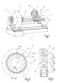
- the in Figure 1 The lathe schematically sketched as an example has a machine frame with a base 1 on which a headstock 2 and a tool turret 3 are each mounted so as to be adjustable in the X and Z directions.
- the headstock 2 is assigned a sleeve 4 which can also be moved in the Z direction and which serves to support a workpiece (not shown in more detail) which is clamped in a chuck indicated at 5 on the spindle 6 mounted in the headstock 2.
- the tool turret 3 has a turret disk 7 which forms a tool carrier and on the circumference of which receptacles 8 for tool holders 9 are provided which are set up for different machining tasks as shown in Figure 1 is indicated schematically.
- Each of the mounts 8 of the polygonal turret disk 7 is provided with a flat support surface 10 ( Figure 2,3 ) through which a central cylindrical receiving bore 11 for the shaft of an attached tool holder 9 extends.
- Each receiving surface 10 is also provided with crosswise arranged receiving grooves 12 for adjusting elements 13 provided on the associated tool holder 9 (see for example Figure 6 ) which, together with the receiving grooves 12, ensure the exact positioning of an attached tool holder 9.
- the turret disk is mounted so as to be rotatable about its axis 16 in a housing 15 of the tool turret 3 containing its drive devices.
- the turret disk 7 can be rotated in cycles about its axis of rotation 16 by its drive device in such a way that at least one of the Tool holder 9 is in a machining position in which the tool provided in it acts on the workpiece.
- the tool holder 9 shown has a housing 17 which is designed with a flat support surface 18 over which the adjusting elements 13 project axially, which surround a centrally arranged cylindrical shaft 19 which, when the tool holder is placed on the turret disk 7, is received in the receiving bore 11 of the respective holder 8.
- the drive shaft for a collet device indicated at 20 and rotatably mounted in the housing 17 for receiving a driven tool runs through the shaft 19.
- the tool drive shaft carries at its end projecting over the shaft 19 a coupling piece 21 for a tool drive device arranged in the area of the turret disk 7, which drives the tool for the machining process when the tool holder 9 is in the machining position.
- the shaft 19 is designed as a tie rod running at right angles to the support surface 18, which cooperates with a clamping device provided on the turret disk 7.
- This clamping device has a clamping element in the form of a slide 22, which is mounted on the turret disk 7 transversely to the shaft 19 and is adjustable between a clamping position and a release position and which is slidably guided in a longitudinal guide 23 assigned to the respective receptacle 8 ( Figure 2 ).
- the slide 22 is rectangular in cross-section and essentially plate-shaped with parallel, opposing broad surfaces 24, 25, of which the lower surface 24 facing the rotation axis 16 of the turret disk 7 is referred to as the first clamping surface.
- Each of the longitudinal guides 23 is provided with a slot-like opening 26 delimited by a parallel surface, which extends from the rear side of the turret disk 7 facing the bearing flange 14 into the receiving bore 11 and which is dimensioned such that it receives the respective slide 22 in a sliding seat.
- the upper boundary wall 230 of the slot-like opening 26 has a narrow tolerance in its position with respect to the support surface 10 of the associated receptacle 8.
- the slide 22 is provided with an approximately semicircular recess 28 on its front end facing the turret disk 7, so that it has an approximately fork-like shape overall. It is connected on its side opposite the recess 28 to a first coupling element 29 located outside the turret disk 7, which is designed in the form of a hook opening towards the circumference of the turret disk 7, as is the case, for example, with the Figures 7 and 9
- the thickness, ie the distance between the broad surfaces 24, 25 of the slide 22, is also closely tolerated, so that the axial distance between the first clamping surface 24 and the support surface 10 corresponds exactly and with close tolerance to a predetermined dimension.
- a second coupling element 30 can be brought into engagement with the first coupling element 29, which is coupled via an actuating rod 31 to an adjusting device 32, which is designed to move the slide 22 in its longitudinal guide via the coupling elements 29, 30. 23 between a clamping position and a release position.
- the adjusting device 32 can, for example, contain a hydraulic cylinder or another mechanical or electromechanical drive element that can be optionally controlled from the outside and allows the actuating rod 31 to be given the aforementioned reciprocating linear movement.
- the hook shape of the complementary coupling elements 29, 30 is configured such that the two coupling elements 29, 30 are in relation to Figure 10 are freely movable transversely to the slide 22. They can therefore be brought into or out of engagement with one another by a rotational movement of the turret disk 7 about the axis 16.
- the shaft 19 of the tool holder 9 is designed to be elastically stretchable to a limited extent in the axial direction.
- the shaft 19 is designed with a region of reduced diameter, which forms an expansion element 33.
- the elastic stretchability of the shaft 19 could also be achieved by other measures, for example by a correspondingly small wall thickness or appropriate incisions or comparable elements that provide the required stretchability.
- the expansion element 33 is limited on the side facing away from the tool holder 9 by an annular shoulder 34, which forms a second clamping surface 35 running at right angles to the axis of the shaft 19.
- This second clamping surface 35 is positioned in such a way that when the tool holder 9 is inserted into the receptacle 8, the first clamping surface 24 located on the underside of the associated slide 22 is positioned by a small predetermined amount below the second clamping surface 35 of the shaft 19, such that when the clamping surfaces 24, 35 are pushed over one another via the slide 22, which is supported radially in the longitudinal guide 23 with respect to the turret disk 7, the shaft 19 is axially elastically stretched in the area of its expansion element 33 to such an extent that the predetermined clamping force required for securely pressing the support surface 18 of the tool holder 9 onto the support surface 10 of the turret disk 7 is generated.
- the stretched shaft 19 acts as a tension rod that acts centrally on the housing 17 of the tool holder 9.
- a run-on slope 330 or 340 is provided, which facilitates the sliding of the slider 22 onto the second clamping surface 35 on the shaft 19.
- the approximately semicircular recess 28 on the slide 22 has a fork width which, with radial play, corresponds to the diameter of the expansion element 33 of the shaft 19, so that when the slide 22 is in the clamping position, a full support of its first clamping surface 24 on the second clamping surface 35 of the shaft 19 is ensured.
- the first clamping surface 24 therefore generally projects radially beyond the central axis of the cylindrical expansion element 33.
- the described clamping device works as follows: Starting from the slide 22 in a retracted release position according to Figure 6 is a tool holder 9 has been inserted in the correct position by an automatic tool holder changing device or manually by an operator with its shaft 19 into the corresponding receiving bore 11 of the associated holder 8 of the turret disk 7.
- the adjusting device 32 is caused by a corresponding control to push the slide 22 forwards against the shaft 19 in such a way that the first clamping surface 24 of the slide 22 is pushed onto the second clamping surface 35 of the shaft 19 via the run-on slopes 330/340 and the shaft 19 is thereby pulled radially inwards so that the required axial clamping force is generated via the expansion element 33, with which the tool holder 9 is pressed onto the turret disk 7.
- the situation when the slide 22 runs onto the second clamping surface 35 is shown in Figure 7 illustrated.
- the slide 22 is moved into the position shown in Figure 8 shown position, in which a secure, full engagement of the two clamping surfaces is ensured.
- the recess 28 can also have insertion bevels 36 at its front end, as shown in Figure 8 is indicated.
- first and second clamping surfaces 24 and 35 are aligned parallel to one another, as mentioned.
- these surfaces form a small angle with one another, for example to enable adjustment of the slides 22 with respect to the respective shaft 19, as may be useful, for example, to compensate for wear or manufacturing tolerances.
- the hook-shaped coupling elements 29, 30 have a sufficiently large play in their hook openings for this purpose. In any case, however, the self-locking mutual engagement of the clamping surfaces must be ensured.
- the slides 22 are actuated from the rear of the turret disk 7.
- the slides are accessible for actuation from the front of the turret disk.
- the second clamping surface 35 does not necessarily have to be formed by an annular shoulder of the shaft 19.
- Other designs, such as grooves, shoulders and the like, are also conceivable.
- the shaft 19 acts as a tension rod that engages centrally on the tool holder, ensuring that the latter is not deformed by the action of the clamping force and the actuation of the clamping elements and that the clamping force acts at right angles to the support surfaces 10, 18.
- the new machine tool with its described tool carrier and its tool holders is especially designed for automatic tool changing.
- the manufacturer of the machine has specified a specific tool changing position of the turret disk 7.
- the tool holder to be changed should be easily accessible in order to ensure problem-free tool holder changing, while another tool holder in the machining position is carrying out a machining operation with its tool.
- the tool holder changing position and the machining position are not directly related. It must only be ensured that the clamping device of the tool holder to be changed can be operated unhindered by a machine operator or a corresponding handling system.
- the turret disk 7 moves into its tool holder changing position, in which the adjusting device 32 is arranged.
- the coupling elements 29, 30 of the slide 22 of the tool holder 9 to be changed come into engagement with one another.
- the adjusting device 32 is now actuated either by the control system of the machine tool or by the machine operator. This pulls the slide 22 out of the turret disk 7 via the actuating rod 31 and the coupling 29/30 so far that it moves into the release position after Figure 6 This unlocks the tool holder 9.
- the type of drive for the adjusting device 32 must be selected appropriately.
- This connection can be made directly via a rod, as shown, but it can also be made via one or more deflections. Only the linear movement of the slide to clamp the tool holder needs to be achieved.
- a threaded rod can also be used, for example, to convert a rotary movement of a motor into a linear movement.
- the adjusting device 32 Since the adjusting device 32 is permanently installed in the machine tool, it is expediently controlled by the machine tool itself. This ensures that the tool holder change is not initiated at an inopportune time.
- the tool holder change can be initiated either by the machine operator or via the machine control system, in which the machine operator gives a corresponding command to the control system.
- the tool holder change can also be carried out fully automatically by a handling system of the machine, whereby the Control of the handling system is coupled with the control of the machine tool to control the tool holder change.
- the clamping force with which the tool holder 9 is clamped on the turret disk 7 is generated by the elastic deformation of the shaft 19.
- a tool holder is assigned several axially elastically deformable tie rods, which interact with clamping elements assigned in the manner described and take the place of the shaft 19 or are present in addition to it.
- the shaft 16 is accommodated with a certain radial play in its receiving bore 11 of the turret disk 7. This prevents the exact positioning of the tool holder 9 on the associated receiving surface 10 of the tool disk 7, which is ensured by the interaction of the adjusting elements 13 with the receiving grooves 12, from being impaired by the shaft being forced into a narrow receiving bore. Particularly with a small shaft diameter, it can therefore be expedient to provide an abutment for the slide in the receiving bore 11 on the side opposite the slide, in order to prevent the shaft from being deflected sideways when the slide 22 is retracted.
- Such an abutment can be provided, for example, by a Figure 9 merely schematically indicated own abutment element 350, for example a screw bolt slightly protruding into the receiving bore 11 or by a corresponding slight lateral offset of at least part of the inner wall of the receiving bore 11.
- the slides 22 are held in their clamping position by friction, without the need for the action of the adjusting device 32.
- the adjusting device 32 For example, in machining processes that generate strong vibrations, such as milling work with interrupted cutting, it may be expedient to provide additional safety measures that prevent the slides 22 from being accidentally released when in the clamping position.
- Such safety devices are described in the Figures 11, 12 illustrated by example:
- the securing means comprise a ring 37 with a rectangular cross-section, which is fixedly mounted on the rear side of the turret disk 7 on the housing 15 of the tool turret 3 ( Figure 1 ) is arranged.
- the ring 37 extends at a small axial distance along the hook-shaped coupling elements 29, the slide 22 created in the clamping position such that these are in relation to Figure 12 are prevented from moving out to the right, ie away from the back of the turret disk 7.
- the ring 37 has an interruption 38, the width of which is such that it allows the passage of the coupling elements 29, 30 of the adjusting device 32 arranged at this point, as can be seen from Figure 11
- the ring 37 is therefore positioned in such a way that it facilitates the tool holder change at the The freely selectable tool holder changing position is not hindered by the circumference of the turret disk 7.
- the invention was explained using a tool carrier in the form of a star turret 3 as an example. However, it is also suitable for tool turrets of a different design and can also be used for tool carriers that carry out a linear movement in order to bring their tools into the respective machining position or into the tool holder changing position.
- the associated slide 22 slides with its first clamping surface 24 over the second clamping surface 35 on the shaft 19 of the tool holder 9, which forms a tie rod.
- the slide 22 is supported by its broad side surface 25 opposite the clamping surface 24 on the upper boundary wall 230 of the slot-like opening 26 of the longitudinal guide 23, so that it can transfer the relatively large clamping force required for clamping the tool holder 9 in the correct position to the shaft 19 acting as a tie rod.
- the interacting Clamping surfaces 24, 35 and 25, 230 must be designed and constructed with such material pairings that the functionality is not impaired by wear on these surfaces even when the machine tool is in operation for longer periods.
- the surfaces 24, 25, 35 and 230 can therefore, for example, be provided with a suitable coating, preferably made of hard materials (for example TiC, TiN, etc.), if necessary individually or in pairs. It is also possible to provide inserts made of a wear-resistant material or coated with such a material on the slide 22 or the slot-like opening 26 of the longitudinal guide 23 which receives it, which inserts support the surfaces 24, 25, 230 and 35.
- the tool holder 9 corresponds in its basic structure to that shown in the Figures 6 to 10 explained tool holder 9, while the tool holders in the Figures 17, 18
- the turret disk 7 shown with the associated clamping devices for the tool holders 9 corresponds to the embodiments according to the Figures 4, 5 Identical parts are therefore provided with the same reference symbols and are not explained again.
- the second clamping surface 35 is formed on a separate annular clamping part 40, the details of which can be seen in particular from the Figures 15, 16 can be seen.
- the clamping part 40 consists of a wear-resistant material, for example a hard material. It can also have a wear-resistant coating on its clamping surface 351 that results in a favorable surface pairing, as already mentioned.
- the clamping part 40 is designed as a ring segment, ie it has a substantially horseshoe-shaped form, the inner diameter of which in the area of the clamping surface 351 corresponds to the diameter of the cylindrical expansion element 33, so that it can be pushed onto the expansion element 33 from the side.
- the clamping part 40 takes up the Figure 13 shown position, in which it rests snugly on the clamping surface 35 ring shoulder 34 of the shaft 19 with its lower support surface 41 opposite the precisely machined second clamping surface 351.
- the support surface 41 is precisely machined. Its axial distance from the parallel clamping surface 351 is set precisely so that the second clamping surface 351 can interact with the clamping surface 24 on the slide 22 in the assembled state in the manner already described.
- annular flange 43 is formed on the shaft 19 on the annular shoulder 34, which has an annular groove 44 on its circumference, into which an annular shoulder 45 of the clamping part 40 can engage, so that the clamping part 40 is held axially immovably on the shaft in the pushed-on state.
- at least one flattening is provided on the peripheral surface of the annular flange 43. 440 is present, which is assigned a corresponding flat on the inside of the clamping part 40 and which ensures that the clamping part 40 pushed onto the shaft 19 is secured against rotation.
- the flat 440 can, for example, be assigned a second corresponding flat on the diametrically opposite side of the shaft, and it is also conceivable to provide several such flats 440 distributed around the circumference of the ring flange 43 in order to be able to clamp the tool holder 9 optionally in several rotational positions of a shaft on the turret slide 7.
- the ring- or horseshoe-shaped clamping part 40 can be easily replaced if signs of wear make this advisable.
- the clamping force occurring during the clamping process can be adjusted to the The dimensions can be adjusted to the respective requirements or a manufacturing tolerance can be compensated.
- the Figures 17, 18 As can be seen, the annular clamping part 40 lies with its closed peripheral area opposite the slide 22, so that it cannot be pushed away from the shaft 19 by the slide 22 during the clamping process.
- the clamping part 40 can also be designed in several parts, just as embodiments of the tool holder are conceivable in which the ring flange 43 is dispensed with or is replaced, for example, by grooves or the like on the shaft 19.
Landscapes
- Engineering & Computer Science (AREA)
- Mechanical Engineering (AREA)
- Cutting Tools, Boring Holders, And Turrets (AREA)
- Gripping On Spindles (AREA)
Applications Claiming Priority (2)
| Application Number | Priority Date | Filing Date | Title |
|---|---|---|---|
| DE102019120522.0A DE102019120522A1 (de) | 2019-07-30 | 2019-07-30 | Werkzeugmaschine mit einem beweglichen Werkzeugträger, Werkzeugträger und Werkzeughalter dafür |
| EP20175642.6A EP3771510B1 (fr) | 2019-07-30 | 2020-05-20 | Machine-outil dotée d'un porte-outil mobile, porte-outil et support d'outil correspondant |
Related Parent Applications (2)
| Application Number | Title | Priority Date | Filing Date |
|---|---|---|---|
| EP20175642.6A Division-Into EP3771510B1 (fr) | 2019-07-30 | 2020-05-20 | Machine-outil dotée d'un porte-outil mobile, porte-outil et support d'outil correspondant |
| EP20175642.6A Division EP3771510B1 (fr) | 2019-07-30 | 2020-05-20 | Machine-outil dotée d'un porte-outil mobile, porte-outil et support d'outil correspondant |
Publications (2)
| Publication Number | Publication Date |
|---|---|
| EP4501505A2 true EP4501505A2 (fr) | 2025-02-05 |
| EP4501505A3 EP4501505A3 (fr) | 2025-05-14 |
Family
ID=70802578
Family Applications (3)
| Application Number | Title | Priority Date | Filing Date |
|---|---|---|---|
| EP24214537.3A Pending EP4491309A3 (fr) | 2019-07-30 | 2020-05-20 | Machine-outil avec un porte-outil mobile, porte-outil et porte-outil pour cette machine-outil |
| EP24220729.8A Pending EP4501505A3 (fr) | 2019-07-30 | 2020-05-20 | Machine-outil avec un porte-outil mobile, porte-outil et porte-outil pour cette machine-outil |
| EP20175642.6A Active EP3771510B1 (fr) | 2019-07-30 | 2020-05-20 | Machine-outil dotée d'un porte-outil mobile, porte-outil et support d'outil correspondant |
Family Applications Before (1)
| Application Number | Title | Priority Date | Filing Date |
|---|---|---|---|
| EP24214537.3A Pending EP4491309A3 (fr) | 2019-07-30 | 2020-05-20 | Machine-outil avec un porte-outil mobile, porte-outil et porte-outil pour cette machine-outil |
Family Applications After (1)
| Application Number | Title | Priority Date | Filing Date |
|---|---|---|---|
| EP20175642.6A Active EP3771510B1 (fr) | 2019-07-30 | 2020-05-20 | Machine-outil dotée d'un porte-outil mobile, porte-outil et support d'outil correspondant |
Country Status (5)
| Country | Link |
|---|---|
| US (2) | US11583938B2 (fr) |
| EP (3) | EP4491309A3 (fr) |
| JP (1) | JP7553277B2 (fr) |
| KR (1) | KR102837353B1 (fr) |
| DE (1) | DE102019120522A1 (fr) |
Families Citing this family (2)
| Publication number | Priority date | Publication date | Assignee | Title |
|---|---|---|---|---|
| DE102019100257A1 (de) * | 2019-01-08 | 2020-07-09 | Esa Eppinger Gmbh | Werkzeugmaschine |
| KR102507278B1 (ko) * | 2021-11-17 | 2023-03-07 | 현대위아 주식회사 | 드리븐툴 장착 기구 및 이를 이용한 드리븐툴 장착 방법 |
Citations (3)
| Publication number | Priority date | Publication date | Assignee | Title |
|---|---|---|---|---|
| DE19940330A1 (de) | 1999-08-25 | 2001-03-15 | Esa Eppinger Gmbh | Werkzeugspanneinrichtung |
| DE102008048206A1 (de) | 2008-09-20 | 2010-04-01 | Sauter Feinmechanik Gmbh | Werkzeugrevolver |
| DE102014119482A1 (de) | 2014-12-23 | 2016-06-23 | Esa Eppinger Gmbh | Werkzeugspanneinrichtung |
Family Cites Families (16)
| Publication number | Priority date | Publication date | Assignee | Title |
|---|---|---|---|---|
| DE2234676C2 (de) * | 1972-07-14 | 1975-02-27 | Gildemeister Ag, 4800 Bielefeld | Anordnung zum Wechseln von mit Werkzeugen bestückten Werkzeughaltern an einer Werkzeugmaschine |
| DD138520B1 (de) * | 1978-05-25 | 1980-07-23 | Volker Thomas | Einrichtung zum werkzeugwechsel fuer eine drehmaschine |
| JPS62157703A (ja) * | 1985-12-27 | 1987-07-13 | Okuma Mach Works Ltd | 工作機械 |
| US5127775A (en) * | 1991-11-01 | 1992-07-07 | Smith & Wesson Corp. | Fail safe stop for a drill press control device |
| JPH0691469A (ja) * | 1992-09-08 | 1994-04-05 | Mori Seiki Co Ltd | 自動工具交換装置を備えたnc旋盤 |
| KR970020283A (ko) * | 1995-10-31 | 1997-05-28 | 유상부 | 내마모성이 우수한 내마모부재와 그 제조방법 |
| US5873682A (en) * | 1997-04-14 | 1999-02-23 | Koyo Corporation Of Usa | Pivoting tool holder |
| JP4285527B2 (ja) * | 2006-10-30 | 2009-06-24 | 三菱マテリアル株式会社 | 切削ヘッド交換式工具およびそのアーバと切削ヘッドとの締結方法 |
| JP5308893B2 (ja) * | 2009-04-03 | 2013-10-09 | 株式会社森精機製作所 | 工作機械の刃物台 |
| DE102014102082A1 (de) * | 2014-02-19 | 2015-08-20 | Ott-Jakob Spanntechnik Gmbh | Werkzeugrevolver |
| DE102017007905A1 (de) * | 2017-08-17 | 2019-02-21 | Oesterle + Partner GbR (vertretungsberechtigter Gesellschafter: Hermann Oesterle, 72202 Nagold, Harald Öschger, 79183 Waldkirch) | Festlegevorrichtung für Werkzeugmaschinen |
| JP2019123063A (ja) * | 2018-01-18 | 2019-07-25 | オークマ株式会社 | ホルダおよび工作機械 |
| EP3536429A1 (fr) * | 2018-03-06 | 2019-09-11 | Daunert Maquinas Herramientas, S.A. | Kit d'aide lors du changement manuel d'un outil dans un porte-outil rotatif |
| DE102019100257A1 (de) * | 2019-01-08 | 2020-07-09 | Esa Eppinger Gmbh | Werkzeugmaschine |
| DE102019104686A1 (de) * | 2019-02-25 | 2020-08-27 | Index-Werke Gmbh & Co. Kg Hahn & Tessky | Werkzeugträger und Werkzeughalter |
| JP2021157703A (ja) * | 2020-03-30 | 2021-10-07 | 富士通株式会社 | 部分形状抽出プログラム、部分形状抽出方法及び情報処理装置 |
-
2019
- 2019-07-30 DE DE102019120522.0A patent/DE102019120522A1/de active Pending
-
2020
- 2020-05-20 EP EP24214537.3A patent/EP4491309A3/fr active Pending
- 2020-05-20 EP EP24220729.8A patent/EP4501505A3/fr active Pending
- 2020-05-20 EP EP20175642.6A patent/EP3771510B1/fr active Active
- 2020-07-28 KR KR1020200093604A patent/KR102837353B1/ko active Active
- 2020-07-28 JP JP2020127174A patent/JP7553277B2/ja active Active
- 2020-07-29 US US16/942,510 patent/US11583938B2/en active Active
-
2023
- 2023-01-10 US US18/152,199 patent/US11945035B2/en active Active
Patent Citations (3)
| Publication number | Priority date | Publication date | Assignee | Title |
|---|---|---|---|---|
| DE19940330A1 (de) | 1999-08-25 | 2001-03-15 | Esa Eppinger Gmbh | Werkzeugspanneinrichtung |
| DE102008048206A1 (de) | 2008-09-20 | 2010-04-01 | Sauter Feinmechanik Gmbh | Werkzeugrevolver |
| DE102014119482A1 (de) | 2014-12-23 | 2016-06-23 | Esa Eppinger Gmbh | Werkzeugspanneinrichtung |
Also Published As
| Publication number | Publication date |
|---|---|
| DE102019120522A1 (de) | 2021-02-04 |
| JP2021041523A (ja) | 2021-03-18 |
| EP4491309A2 (fr) | 2025-01-15 |
| US11583938B2 (en) | 2023-02-21 |
| EP3771510B1 (fr) | 2025-01-29 |
| EP4501505A3 (fr) | 2025-05-14 |
| US20230166337A1 (en) | 2023-06-01 |
| US20210031274A1 (en) | 2021-02-04 |
| JP7553277B2 (ja) | 2024-09-18 |
| EP4491309A3 (fr) | 2025-04-09 |
| EP3771510A1 (fr) | 2021-02-03 |
| KR20210014585A (ko) | 2021-02-09 |
| KR102837353B1 (ko) | 2025-07-24 |
| US11945035B2 (en) | 2024-04-02 |
Similar Documents
| Publication | Publication Date | Title |
|---|---|---|
| DE102014119482A1 (de) | Werkzeugspanneinrichtung | |
| DE102010043667A1 (de) | Werkzeugmaschine mit Werkzeughalterung | |
| DE4028775C1 (fr) | ||
| DE3904259C2 (fr) | ||
| DE8505616U1 (de) | Werkzeugadapter für eine Spindel von Bohr-, Fräs- und dgl. Werkzeugmaschinen | |
| DE3913139C2 (fr) | ||
| DE3010934C2 (fr) | ||
| DE3209999A1 (de) | Werkzeugkopf und wechseleinrichtung an werkzeugmaschinen | |
| EP3771510B1 (fr) | Machine-outil dotée d'un porte-outil mobile, porte-outil et support d'outil correspondant | |
| EP1884303B1 (fr) | Procédé destiné à centrer des pièces à usiner tout comme dispositif destiné à la réalisation d'un tel procédé | |
| DE3323502C1 (de) | Revolver-Drehautomat | |
| EP3651922B1 (fr) | Dispositif changeur d'outil, machine-outil pourvue d'un tel dispositif changeur d'outil et procédé associé | |
| EP3682990B1 (fr) | Dispositif de sécurité | |
| DE2840129A1 (de) | Befestigungsvorrichtung zum halten eines werkstuecks an einer werkzeugmaschine | |
| EP1147838B1 (fr) | Machine-outil et mandrin | |
| EP4003643A1 (fr) | Cocon de machine-outil, procédé et programme informatique destiné à faire fonctionner une machine-outil comprenant un tel cocon de machine-outil | |
| EP0166887B1 (fr) | Dispositif pour le changement rapide des mordaches | |
| DE3341252A1 (de) | Automatische werkzeugwechseleinrichtung | |
| WO2019020783A1 (fr) | Dispositif d'ajustement pour un outil d'usinage par enlèvement de copeaux et outil d'usinage par enlèvement de copeaux présentant un dispositif d'ajustement | |
| EP3684533B1 (fr) | Tournage de pièces à usiner sur une machine-outil | |
| EP3658319B1 (fr) | Outil d'usinage par enlèvement de copeaux et procédé pour l'usinage d'une roulement d'un palier | |
| DE9015333U1 (de) | Vorrichtung zum Wechseln von Werkzeugen an Werkzeugmaschinen | |
| EP1038618A2 (fr) | Tête d'outil pour un tour | |
| DE3100908C2 (de) | Spannfutter für Drehmaschinen u. dgl. Werkzeugmaschinen | |
| DE3930787A1 (de) | Einrichtung zur spanabhebenden bearbeitung, insbesondere fraeseinrichtung, fuer den werkzeugrevolver von werkzeugmaschinen |
Legal Events
| Date | Code | Title | Description |
|---|---|---|---|
| PUAI | Public reference made under article 153(3) epc to a published international application that has entered the european phase |
Free format text: ORIGINAL CODE: 0009012 |
|
| STAA | Information on the status of an ep patent application or granted ep patent |
Free format text: STATUS: THE APPLICATION HAS BEEN PUBLISHED |
|
| AC | Divisional application: reference to earlier application |
Ref document number: 3771510 Country of ref document: EP Kind code of ref document: P |
|
| AK | Designated contracting states |
Kind code of ref document: A2 Designated state(s): AL AT BE BG CH CY CZ DE DK EE ES FI FR GB GR HR HU IE IS IT LI LT LU LV MC MK MT NL NO PL PT RO RS SE SI SK SM TR |
|
| REG | Reference to a national code |
Ref country code: DE Ref legal event code: R079 Free format text: PREVIOUS MAIN CLASS: B23B0029040000 Ipc: B23B0029240000 |
|
| PUAL | Search report despatched |
Free format text: ORIGINAL CODE: 0009013 |
|
| AK | Designated contracting states |
Kind code of ref document: A3 Designated state(s): AL AT BE BG CH CY CZ DE DK EE ES FI FR GB GR HR HU IE IS IT LI LT LU LV MC MK MT NL NO PL PT RO RS SE SI SK SM TR |
|
| RIC1 | Information provided on ipc code assigned before grant |
Ipc: B23B 29/04 20060101ALI20250409BHEP Ipc: B23B 29/20 20060101ALI20250409BHEP Ipc: B23B 29/24 20060101AFI20250409BHEP |
|
| STAA | Information on the status of an ep patent application or granted ep patent |
Free format text: STATUS: REQUEST FOR EXAMINATION WAS MADE |
|
| 17P | Request for examination filed |
Effective date: 20250919 |