EP4501545A1 - Plateau et dispositif à plateau - Google Patents
Plateau et dispositif à plateau Download PDFInfo
- Publication number
- EP4501545A1 EP4501545A1 EP23864585.7A EP23864585A EP4501545A1 EP 4501545 A1 EP4501545 A1 EP 4501545A1 EP 23864585 A EP23864585 A EP 23864585A EP 4501545 A1 EP4501545 A1 EP 4501545A1
- Authority
- EP
- European Patent Office
- Prior art keywords
- positioning
- seat
- pallet
- support plate
- driving member
- Prior art date
- Legal status (The legal status is an assumption and is not a legal conclusion. Google has not performed a legal analysis and makes no representation as to the accuracy of the status listed.)
- Pending
Links
Images


Classifications
-
- B—PERFORMING OPERATIONS; TRANSPORTING
- B25—HAND TOOLS; PORTABLE POWER-DRIVEN TOOLS; MANIPULATORS
- B25B—TOOLS OR BENCH DEVICES NOT OTHERWISE PROVIDED FOR, FOR FASTENING, CONNECTING, DISENGAGING, OR HOLDING
- B25B11/00—Work holders not covered by any preceding group in the subclass, e.g. magnetic work holders, vacuum work holders
- B25B11/02—Assembly jigs
Definitions
- the present disclosure relates to the technical field of battery manufacturing equipment, and particularly to a pallet and a pallet device.
- a battery module includes a plurality of battery cells, and when assembling the battery module, each battery cell is placed into the pallet, and the pallet provides positioning for the battery module.
- the pallet is conveyed by a conveying mechanism and enters each processing station on a battery module assembly equipment in sequence to complete the assembly of the battery module.
- the pallet generally includes a support plate, a first restraining block and a moving assembly, the first restraining block is fixed to the support plate, and the moving assembly is movable relative to the support plate.
- the battery module is provided between the first restraining block and the moving assembly.
- the moving assembly may move in a direction approaching the first restraining block so as to clamp and position the battery module.
- the moving assembly in order to position battery modules of different lengths, is provided with a screw rod and a pressing block, the pressing block is connected to one end of the screw rod, and the other end of the screw rod is provided with a cooperating hole.
- the positioning pin is connected to a motor, and may be inserted into the cooperating hole. The motor drives the positioning pin to rotate, and then rotation of the screw rod allows the pressing block to move in the direction approaching the first restraining block; the pressing block and the first restraining block cooperate to clamp the battery module.
- the present disclosure is intended to alleviate or solve, at least in part, at least one of the above-mentioned problems.
- the present disclosure proposes a pallet, including: a support plate; a first restraining block provided on the support plate; a moving assembly including a moving seat and a positioning member, the moving seat being slidably provided on the support plate in a first direction and being capable of approaching or moving away from the first restraining block to cooperate with the first restraining block to clamp or release a workpiece, and the positioning member being movably provided on the moving seat in a second direction to switch between a first position and a second position relative to the moving seat; wherein the support plate is provided with at least two positioning hole groups which are spaced apart from each other in the first direction, and each positioning hole group includes at least one positioning hole arranged in a third direction; when the positioning member is in the first position, the positioning member is capable of selectively inserting into one of the positioning hole groups, and when the positioning member is in the second position, the positioning member is detached from the positioning hole group; and the first direction, the second direction, and the third direction intersect with each
- the moving assembly further includes: an elastic member provided between the moving seat and the positioning member for providing a preloading force to the positioning member so that the positioning member is inserted into the positioning hole group.
- the positioning member includes: a connecting seat and a positioning pin, the positioning pin being connected to the connecting seat and being capable of inserting through the moving seat;
- the moving assembly further includes a connecting rod which includes a rod body and a head connected to each other, the rod body extends in the second direction, and one end of the rod body distal to the head passes through the connecting seat to be fixedly connected to the moving seat; the elastic member is sleeved onto the rod body and abuts between the head of the connecting rod and the connecting seat.
- the positioning member has a cooperating hole opened in the third direction, and the cooperating hole is configured to allow insertion of an external equipment, so as to enable the positioning member to switch between the first position and the second position.
- the positioning hole is a waist-shaped hole extending in the third direction.
- the moving seat includes: a seat body slidably connected to the support plate; a pressing block provided on the seat body; an abutting block connected to the pressing block and cooperating with the first restraining block to clamp or release the workpiece.
- the moving assembly further includes: a fixing member and an adjusting member, the fixing member fixing the pressing block to the seat body, and the adjusting member abutting against a side of the pressing block that is distal to the first restraining block;
- the adjusting member is turned to adjust a spacing between the pressing block and the first restraining block.
- the pallet further includes: two supporting blocks, which are spaced apart from each other in the third direction, and are provided on the same surface of the support plate as the first restraining block and the moving assembly, each of the supporting blocks includes at least two second restraining blocks spaced apart from each other in the first direction, and the second restraining blocks included in the two supporting blocks are in one-to-one opposition in the third direction.
- the present disclosure proposes a pallet device, including: the pallet and the adjusting mechanism according to any one of the above, the adjusting mechanism is capable of cooperating with the positioning member to enable the positioning member to switch between the first position and the second position, and is capable of driving the moving assembly to move in the first direction relative to the support plate.
- the positioning member has a cooperating hole opened in the third direction;
- the adjusting mechanism includes: a first driving member, and a second driving member connected to the first driving member; a third driving member connected to the second driving member, and an insertion pin connected to the third driving member;
- the first driving member is capable of driving the second driving member, the third driving member and the insertion pin to move in the first direction
- the second driving member is capable of driving the third driving member and the insertion pin to move in the second direction
- the third driving member is capable of driving the insertion pin to move in the third direction to insert into or detach from the cooperating hole.
- the pallet and the pallet device proposed by the present disclosure by locking the position of the moving seat by inserting the positioning member into the positioning hole group, it is possible to allow the moving seat to move accurately to the preset position so as to cooperate with the first restraining block to clamp the battery module, which improves the positioning accuracy compared with the prior art.
- first and second are only used for descriptive purposes and should not be understood as indicating or implying relative importance or implying a number of indicated technical features. Therefore, a feature delimited with “first”, “second” may expressly or implicitly include at least one of those features.
- a plurality means at least two, such as two, three, etc., unless expressly and specifically defined otherwise.
- a first feature "on” or “under” a second feature may be that the first feature is in direct contact with the second feature, or the first feature and the second feature are indirectly contacted through an intermediary.
- the first feature being “above”, “over” and “on” the second feature may mean that the first feature is directly above or obliquely above the second feature, or simply means that the first feature is on a higher horizontal level than the second feature.
- the first feature being “below”, “under” and “beneath” the second feature may mean that the first feature is directly below or obliquely below the second feature, or simply means that the first feature is on a lower horizontal level than the second feature.
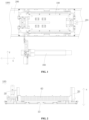
- an embodiment of the present disclosure provides a pallet device 1000, including a pallet 100 configured for positioning a workpiece. Further, the pallet device 1000 further includes a conveying mechanism 200 configured for conveying the pallet 100 to convey the workpiece located on the pallet 100 to a corresponding station for performing a corresponding operation.
- the conveying mechanism 200 is provided with a blocking cylinder 201, which is configured for blocking the pallet 100 to keep it stationary at a preset position.
- the pallet device 1000 of the present disclosure will be described in detail by taking the pallet device 1000 applied to positioning and conveying the battery module as an example.
- this description does not limit the protection scope of the present disclosure, i.e., in other embodiments, it is possible that the workpiece is not a battery module, and may be determined depending on needs.
- the pallet 100 includes a support plate 10, a first restraining block 20, and a moving assembly 30.
- the first restraining block 20 is fixedly provided on the support plate 10
- the moving assembly 30 is slidably provided on the support plate 10 in a first direction and is capable of approaching or moving away from the first restraining block 20 so as to cooperate with the first restraining block 20 to clamp or release the battery module. That is, when it is necessary to clamp and position the battery module, the battery module is placed between the first restraining block 20 and the moving assembly 30, and the moving assembly 30 approaches the first restraining block 20 in the first direction to clamp the battery module.
- the first direction may be the X direction in FIG. 1 .
- the moving assembly 30 moves away from the first restraining block 20 in the first direction to release the battery module, so as to facilitate removal of the battery module from the support plate 10.
- the moving assembly 30 includes a moving seat 31 and a positioning member 32.
- the moving seat 31 is slidably connected to the support plate 10 in the first direction and cooperates with the first restraining block 20 to clamp or release the battery module.
- the positioning member 32 is movably provided on the moving seat 31 in a second direction to switch between a first position and a second position relative to the moving seat 31.
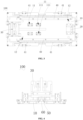
- the first direction may be the Z direction in FIG. 2 .
- the first direction intersects with the second direction. Specifically, the first direction is perpendicular to the second direction.
- the first direction is the X direction in FIG. 1 .
- the second direction is the direction perpendicular to the paper surface in FIG. 1 , and is also the Z direction in FIG 2 .
- the support plate 10 is provided with at least two positioning hole groups 11 spaced apart from each other in the first direction, and each positioning hole group 11 includes one positioning hole 111 arranged in a third direction.
- the first direction, the second direction, and the third direction intersect with each other. Specifically, the first direction, the second direction, and the third direction are mutually perpendicular.
- the third direction is the Y direction in FIG. 1 .
- the positioning member 32 When the positioning member 32 is in the first position, the positioning member 32 is capable of selectively inserting into one of the positioning hole groups 11; when the positioning member 32 is in the second position, the positioning member 32 is detached from the positioning hole group 11.
- the moving assembly 30 is controlled to move in the first direction to a positioning hole group 11 matching the length of the battery module, the positioning member 32 is inserted into the positioning hole group 11, and the moving seat 31 cooperates with the first restraining block 20 to position the battery module, thereby accommodating battery modules of different lengths.
- the positioning member 32 When there is no need to position the battery module, the positioning member 32 only needs to be detached from the positioning hole group 11.
- the pallet device 100 by locking the position of the moving seat 31 by inserting the positioning member 32 into the positioning hole group 11, it is possible to allow the moving seat 31 to move accurately to the preset position so as to cooperate with the first restraining block 20 to clamp the battery module, which improves the positioning accuracy compared with the prior art.
- the moving assembly 30 is directly opposite to the first restraining block 20 in the first direction, and when they clamp the battery module, it is possible to ensure balanced force application on the battery module, preventing damage to the battery module.
- the moving seat 31 includes a seat body 311, a pressing block 312, and an abutting block 313.
- the seat body 311 is slidably connected to the support plate 10.
- the pressing block 312 is provided on the seat body 311, and the abutting block 313 is connected to the pressing block 312 and cooperates with the first restraining block 20 to clamp or release the battery module.
- the seat body 311 is provided with a first slider 50, while the support plate 10 is provided with a first guide rail 60.
- the seat body 311 is slidably connected to the support plate 10 through the cooperation of the first slider 50 with the first guide rail 60.
- the moving seat 31 includes at least two abutting blocks 313 spaced apart from each other in the third direction.
- the moving seat 31 could include only one abutting block 313, which is not limited herein.
- the moving assembly 30 further includes a fixing member 33 and an adjusting member 34.
- the fixing member 33 fixes the pressing block 312 to the seat body 311, and the adjusting member 34 abuts against a side of the pressing block 312 that is distal to the first restraining block 20.
- the fixing member 33 releases the pressing block 312, the adjusting member 34 is turned to adjust a spacing between the pressing block 312 and the first restraining block 20.
- the pressing block 312 is provided with a waist-shaped hole extending in the first direction.
- the fixing member 33 is a fastening screw that passes through the waist-shaped hole and the seat body 311 to fix the two.
- the fastening screw is loosened;
- the adjusting member 34 is an adjusting screw, and it is possible to adjust the relative position of the pressing block 312 and the seat body 311 by turning the adjusting screw.
- the seat body 311 includes a body 3111 and a connecting block 3112.
- the connecting block 3112 is provided on the seat body 311, and the adjusting member 34 is mounted on the connecting block 3112.
- the adjusting member 34 may be directly mounted on the body 3111 with the connecting block 3112 omitted.
- the support plate 10 is provided with three positioning hole groups 11.
- the positioning member 32 When the positioning member 32 is in the first position, it is capable of selectively inserting into one of the three positioning hole groups 11.
- the support plate 10 By providing the support plate 10 with three positioning hole groups 11, it is possible to clamp battery modules of three different lengths. It should be understood that, in some other embodiments, there is no restriction to the number of the positioning hole groups 11 opened on the support plate 10. For example, two, or more than three positioning hole groups 11 may be opened in the support plate 10.
- the positioning hole 111 is a waist-shaped hole extending in the third direction to allow the insertion of the positioning member 32 into the positioning holes 111.
- the positioning member 32 includes a connecting seat 321 and a positioning pin 322 connected to the connecting seat 321.
- the connecting seat 321 is provided on the pressing block 312, and the positioning pin 322 pass through the pressing block 312 and the seat body 311 and is provided in them.
- the positioning pin 322 may protrude from the seat body 311 and insert into the positioning hole 111.
- each positioning hole group 11 is provided to include at least two positioning holes 111 spaced apart from each other in the third direction, and the number of the positioning pins 322 is also at least two.
- the seat body 311 is fixedly provided with a linear bearing therein, and the positioning pin 322 is provided in the linear bearing and slidably connected thereto so as to improve the positioning accuracy.
- the positioning pin 322 is inserted into the pressing block 312 and the seat body 311, it does not interfere with the relative positions of the pressing block 312 and the seat body 311 when adjusting the relative position.
- the moving assembly 30 further includes an elastic member 35, which is provided on the moving seat 31 and is configured for providing a preloading force to the positioning member 32 to enable the positioning member 32 to be inserted into the positioning hole group 11.
- the moving assembly 30 further includes a connecting rod 36 which includes a rod body 362 and a head 361 connected to each other, the rod body 362 extends in the second direction, and one end of the rod body 362 distal to the head 361 passes through the connecting seat 321 and the pressing block 312 to be fixedly connected to the seat body 311.
- the elastic member 35 is sleeved onto the rod body 362 and abuts between the head 361 of the connecting rod 36 and the connecting seat 321.
- the elastic member 35 accumulates energy, and when the external force disappears, the positioning member 32 switches from the second position to the first position and stays there under the action of the elastic member 35.
- the rod body 362 passes through the connecting seat 321, it also serves to guide the movement of the connecting seat 321.
- connecting rods 36 and the elastic members 35 there are provided a plurality of the connecting rods 36 and the elastic members 35, with the elastic members 35 being springs, where each spring is sleeved onto one connecting rod 36.
- the number of connecting rods 36 and elastic members 35 is not limited, and the type of elastic member 35 is also not limited.
- the positioning member 32 further includes a cooperating part 323, which is connected to the connecting seat 321 and has a cooperating hole 3231 opened in the third direction.
- the cooperating hole 3231 is configured to allow insertion of an external equipment, so as to enable the positioning member 32 to switch between the first position and the second position.
- the cooperating hole 3231 penetrates through the cooperating part 323 in the third direction and is opened therein.
- the cooperating hole 3231 is provided as a waist-shaped hole extending in the second direction to facilitate the insertion of an external device.
- the pallet 100 further includes two supporting blocks 40, which are spaced apart from each other in the third direction, and are provided on the same surface of the support plate 10 as the first restraining block 20 and the moving assembly 30.
- Each of the supporting blocks 40 includes at least two second restraining blocks 41 spaced apart from each other in the first direction, and the second restraining blocks 41 included by the two support plates 10 are in one-to-one opposition in the third direction.
- the battery module is placed between the two supporting blocks 40, and the second restraining blocks 41 in one-to-one opposition in the third direction may position the battery module from two sides thereof.
- the pallet device 1000 further includes an adjusting mechanism 300, which is capable of cooperating with the positioning member 32 to enable the positioning member 32 to switch between the first position and the second position, and is capable of driving the moving assembly 30 to move in the first direction relative to the support plate 10.
- an adjusting mechanism 300 which is capable of cooperating with the positioning member 32 to enable the positioning member 32 to switch between the first position and the second position, and is capable of driving the moving assembly 30 to move in the first direction relative to the support plate 10.
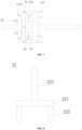
- the adjusting mechanism 300 includes a first driving member 301, a second driving member 302, a third driving member 303, and an insertion pin 304.
- the second driving member 302 is mounted on the first driving member 301, the third driving member 303 is connected to the second driving member 302, and the insertion pin 304 is connected to the third driving member 303.
- the first driving member 301 may drive the second driving member 302, the third driving member 303, and the insertion pin 304 to move in the first direction.
- the second driving member 302 may drive the third driving member 303 and the insertion pin 304 to move in the second direction.
- the third driving member 303 may drive the insertion pin 304 to move in the third direction to insert into or detach from the cooperating hole 3231.
- the third driving member 303 acts to drive the insertion pin 304 to perform forward movement in the third direction to insert into the cooperating hole 3231.
- the second driving member 302 acts to drive the third driving member 303 and the insertion pin 304 to perform forward movement in the second direction, causing the positioning pin 322 to detach from the positioning hole group 11.
- the first driving member 301 acts to drive the second driving member 302, the third driving member 303, and the insertion pin 304 to move in the first direction, causing the moving assembly 30 to move relative to the support plate 10.
- the second driving member 302 acts to drive the third driving member 303 and the insertion pin 304 to perform reverse movement in the second direction, causing the positioning pin 322 to insert into another positioning hole group 11.
- the third driving member 303 acts to drive the insertion pin 304 to perform reverse movement in the third direction to detach from the cooperating hole 3231.
- the positioning member 32 remains in the first position due to the action of the elastic member 35.
- the first driving member 301 uses a servo-driven component, which ensures the movement precision of the moving assembly 30.
- the adjusting mechanism 300 further includes a first mounting seat 305, a second mounting seat 306, and a third mounting seat 307.
- the first mounting seat 305 is connected to a first drive end of the first driving member 301
- the second driving member 302 is fixedly provided on the first mounting seat 305
- the second mounting seat 306 is connected to a second drive end of the second driving member 302
- the third driving member 303 is fixedly provided on the second mounting seat 306
- the third mounting seat 307 is connected to a third drive end of the third driving member 303
- the insertion pin 304 is fixedly provided on the third mounting seat 307.
- the adjusting mechanism 300 further includes a second slider and a second guide rail.
- the second guide rail is provided on the first mounting seat 305
- the second slider is provided on the second mounting seat 306, and the second mounting seat 306 is slidably connected to the first mounting seat 305 via the cooperation of the second slider and the second guide rail.
- the adjusting mechanism 300 further includes a third slider and a third guide rail.
- the third slider is provided on the third mounting seat 307
- the third guide rail is provided on the second mounting seat 306, and the third mounting seat 307 is slidably connected to the second mounting seat 306 via the cooperation of the third slider and the third guide rail.
- the adjusting mechanism 300 further includes a first restraining member 308 and a second restraining member 309.
- the first restraining member 308 is configured for restraining the position of the insertion pin 304 to move in the second direction
- the second restraining member 309 is configured for restraining the position of the insertion pin 304 to move in the third direction.
- the support plate 10 of the pallet 100 is further opened with a elevation hole 12.
- a jacking pin from the jacking mechanism is inserted into this elevation hole 12 to drive the pallet 100 to detach from the conveying mechanism 200, ensuring the repeatable positioning accuracy of the pallet 100.
- This jacking mechanism may be driven by a pneumatic cylinder.
- Another embodiment of the present disclosure also provides a pallet 100 included in the above pallet device 1000.
- the working principle of the pallet device 1000 provided by the embodiments of the present disclosure is as follows: In an initial state, the positioning pin 322 is inserted into one of the positioning hole groups 11.
- the first driving member 301 acts to drive the second driving member 302, the third driving member 303 and the insertion pin 304 to move in the first direction to reach the preset position.
- the third driving member 303 acts to drive the insertion pin 304 to perform forward movement in the third direction to insert into the cooperating hole 3231.
- the second driving member 302 acts to drive the third driving member 303 and the insertion pin 304 to perform forward movement in the second direction, causing the positioning pin 322 to detach from the positioning hole group 11 and the elastic member 35 to accumulate energy.
- the first driving member 301 acts again to drive the second driving member 302, the third driving member 303 and the insertion pin 304 to move in the first direction, thereby driving the moving assembly 30 to move to an appropriate position and thus avoiding interfering with the placement of the battery module on the support plate 10.
- the first driving member 301 acts again to drive the moving assembly 30 by means of the insertion pin 304 to move to the preset position.
- the second driving member 302 acts to drive the third driving member 303 and the insertion pin 304 to perform reverse movement in the second direction, causing the insertion pin 304 to insert into the positioning hole group 11.
- the third driving member 303 acts to drive the insertion pin 304 to perform reverse movement in the third direction to detach from the cooperating hole 3231, and the positioning member 32 remains in the first position due to the action of the elastic member 35.
Landscapes
- Engineering & Computer Science (AREA)
- Mechanical Engineering (AREA)
- Automatic Assembly (AREA)
- Battery Mounting, Suspending (AREA)
- Jigs For Machine Tools (AREA)
- Feeding Of Workpieces (AREA)
Applications Claiming Priority (2)
| Application Number | Priority Date | Filing Date | Title |
|---|---|---|---|
| CN202222421886.XU CN218504300U (zh) | 2022-09-13 | 2022-09-13 | 托盘及托盘装置 |
| PCT/CN2023/116588 WO2024055853A1 (fr) | 2022-09-13 | 2023-09-01 | Plateau et dispositif à plateau |
Publications (2)
| Publication Number | Publication Date |
|---|---|
| EP4501545A1 true EP4501545A1 (fr) | 2025-02-05 |
| EP4501545A4 EP4501545A4 (fr) | 2026-03-11 |
Family
ID=85210563
Family Applications (1)
| Application Number | Title | Priority Date | Filing Date |
|---|---|---|---|
| EP23864585.7A Pending EP4501545A4 (fr) | 2022-09-13 | 2023-09-01 | Plateau et dispositif à plateau |
Country Status (4)
| Country | Link |
|---|---|
| EP (1) | EP4501545A4 (fr) |
| CN (1) | CN218504300U (fr) |
| TR (1) | TR2024014376U5 (fr) |
| WO (1) | WO2024055853A1 (fr) |
Families Citing this family (9)
| Publication number | Priority date | Publication date | Assignee | Title |
|---|---|---|---|---|
| CN218504300U (zh) * | 2022-09-13 | 2023-02-21 | 无锡先导智能装备股份有限公司 | 托盘及托盘装置 |
| EP4506106A4 (fr) * | 2023-06-21 | 2025-02-12 | Contemporary Amperex Technology (Hong Kong) Limited | Support de module et appareil de production de batterie |
| CN117049101A (zh) * | 2023-10-11 | 2023-11-14 | 宁德时代新能源科技股份有限公司 | 托盘、夹紧方法及电池生产线 |
| CN117049219B (zh) * | 2023-10-12 | 2024-02-06 | 宁德时代新能源科技股份有限公司 | 一种快换平台、电池生产线及控制方法 |
| EP4570718B1 (fr) | 2023-10-12 | 2026-04-01 | Contemporary Amperex Technology (Hong Kong) Limited | Plateforme à changement rapide, ligne de production de batterie et procédé de commande |
| CN117068530B (zh) * | 2023-10-13 | 2024-04-02 | 宁德时代新能源科技股份有限公司 | 托盘结构及其使用方法、运输系统、电池加工系统 |
| CN117564831B (zh) * | 2023-11-13 | 2026-03-17 | 中山市创怡兴实业有限公司 | 辊支撑装置及辊加工设备 |
| CN118329912A (zh) * | 2024-04-18 | 2024-07-12 | 苏州恒视智能科技有限公司 | 新能源电芯模组外观ccd检测设备 |
| CN119108324A (zh) * | 2024-09-26 | 2024-12-10 | 无锡先导智能装备股份有限公司 | 定位机构及其定位方法 |
Family Cites Families (10)
| Publication number | Priority date | Publication date | Assignee | Title |
|---|---|---|---|---|
| JP3652383B2 (ja) * | 1994-06-02 | 2005-05-25 | 東芝電池株式会社 | 二次電池の充・放電用トレイ収納・装着装置 |
| CN200977607Y (zh) * | 2006-12-11 | 2007-11-21 | 比亚迪股份有限公司 | 一种定位装置 |
| CN110364765B (zh) * | 2019-05-29 | 2022-08-09 | 合肥国轩高科动力能源有限公司 | 一种锂电池模组打包自动压紧装置 |
| CN110340826B (zh) * | 2019-07-22 | 2024-06-07 | 昆山华誉自动化科技有限公司 | 一种叠芯定位装置 |
| CN212217562U (zh) * | 2020-02-14 | 2020-12-25 | 大族激光科技产业集团股份有限公司 | 动力电池的焊前定位装置 |
| CN213595358U (zh) * | 2020-09-25 | 2021-07-02 | 无锡先导智能装备股份有限公司 | 一种输送装置及电芯输送系统 |
| CN216943359U (zh) * | 2021-05-07 | 2022-07-12 | 宝能(广州)汽车研究院有限公司 | 用于汽车底盘装配的托盘设备及汽车生产系统 |
| CN216084990U (zh) * | 2021-10-14 | 2022-03-18 | 宁德时代新能源科技股份有限公司 | 电池模组成组夹具及装置 |
| CN114976443B (zh) * | 2022-06-24 | 2024-08-13 | 广州明珞装备股份有限公司 | 一种定位组件、托盘模组及输送装置 |
| CN218504300U (zh) * | 2022-09-13 | 2023-02-21 | 无锡先导智能装备股份有限公司 | 托盘及托盘装置 |
-
2022
- 2022-09-13 CN CN202222421886.XU patent/CN218504300U/zh active Active
-
2023
- 2023-09-01 WO PCT/CN2023/116588 patent/WO2024055853A1/fr not_active Ceased
- 2023-09-01 TR TR2024/014376U patent/TR2024014376U5/tr unknown
- 2023-09-01 EP EP23864585.7A patent/EP4501545A4/fr active Pending
Also Published As
| Publication number | Publication date |
|---|---|
| EP4501545A4 (fr) | 2026-03-11 |
| WO2024055853A1 (fr) | 2024-03-21 |
| TR2024014376U5 (tr) | 2024-11-21 |
| CN218504300U (zh) | 2023-02-21 |
Similar Documents
| Publication | Publication Date | Title |
|---|---|---|
| EP4501545A1 (fr) | Plateau et dispositif à plateau | |
| US7415758B2 (en) | Device to press the shaft of a rotor into a stator housing | |
| CN111948550B (zh) | 用于电芯测试的拘束托盘 | |
| CN100537150C (zh) | 夹具装置 | |
| EP4670864A1 (fr) | Appareil de cintrage et dispositif de cintrage flottant associé | |
| CN113655243B (zh) | 多工位测试系统 | |
| CN113263633B (zh) | 刻划头及刻划装置 | |
| CN119165204A (zh) | 探针间隔调节装置以及系统 | |
| KR20090066369A (ko) | 공극조정장치를 포함한 리니어모터 | |
| CN117767474A (zh) | 一种不同厚度电池膨胀收缩自动调节装置 | |
| CN115837682B (zh) | 抓手装置及抓手系统 | |
| CN222447807U (zh) | 一种弯折装置及其浮动弯折设备 | |
| CN220155636U (zh) | 定位装置及电池制造设备 | |
| KR20120070522A (ko) | 부품 실장 장치 | |
| CN111048356A (zh) | 继电器外壳组立装置 | |
| CN216803105U (zh) | 固定装置 | |
| CN215010877U (zh) | 折弯设备 | |
| CN117023123A (zh) | 物料搬运装置和用于该物料搬运装置的间距调节方法 | |
| CN112499272B (zh) | 堆叠设备、堆叠装置及堆叠方法 | |
| CN210879306U (zh) | Fpc板的定位装置 | |
| CN116161405A (zh) | 固定装置以及输送设备 | |
| CN120870839B (zh) | 芯片测试夹具及芯片测试组件 | |
| CN114425503A (zh) | 一种载具及注胶设备 | |
| TR2024014376T7 (tr) | Palet ve palet ci̇hazi | |
| CN223961166U (zh) | 一种定位装置 |
Legal Events
| Date | Code | Title | Description |
|---|---|---|---|
| STAA | Information on the status of an ep patent application or granted ep patent |
Free format text: STATUS: THE INTERNATIONAL PUBLICATION HAS BEEN MADE |
|
| PUAI | Public reference made under article 153(3) epc to a published international application that has entered the european phase |
Free format text: ORIGINAL CODE: 0009012 |
|
| STAA | Information on the status of an ep patent application or granted ep patent |
Free format text: STATUS: REQUEST FOR EXAMINATION WAS MADE |
|
| 17P | Request for examination filed |
Effective date: 20241029 |
|
| AK | Designated contracting states |
Kind code of ref document: A1 Designated state(s): AL AT BE BG CH CY CZ DE DK EE ES FI FR GB GR HR HU IE IS IT LI LT LU LV MC ME MK MT NL NO PL PT RO RS SE SI SK SM TR |
|
| DAV | Request for validation of the european patent (deleted) | ||
| DAX | Request for extension of the european patent (deleted) | ||
| A4 | Supplementary search report drawn up and despatched |
Effective date: 20260206 |
|
| RIC1 | Information provided on ipc code assigned before grant |
Ipc: B25B 11/00 20060101AFI20260202BHEP Ipc: B25B 11/02 20060101ALI20260202BHEP |