EP4501568A1 - Robot de forage à conduite autonome et positionnement précis - Google Patents
Robot de forage à conduite autonome et positionnement précis Download PDFInfo
- Publication number
- EP4501568A1 EP4501568A1 EP23893524.1A EP23893524A EP4501568A1 EP 4501568 A1 EP4501568 A1 EP 4501568A1 EP 23893524 A EP23893524 A EP 23893524A EP 4501568 A1 EP4501568 A1 EP 4501568A1
- Authority
- EP
- European Patent Office
- Prior art keywords
- ground vehicle
- drilling
- unmanned ground
- manipulator
- automatic driving
- Prior art date
- Legal status (The legal status is an assumption and is not a legal conclusion. Google has not performed a legal analysis and makes no representation as to the accuracy of the status listed.)
- Pending
Links
Images




Classifications
-
- B—PERFORMING OPERATIONS; TRANSPORTING
- B28—WORKING CEMENT, CLAY, OR STONE
- B28D—WORKING STONE OR STONE-LIKE MATERIALS
- B28D7/00—Accessories specially adapted for use with machines or devices of the preceding groups
-
- B—PERFORMING OPERATIONS; TRANSPORTING
- B23—MACHINE TOOLS; METAL-WORKING NOT OTHERWISE PROVIDED FOR
- B23B—TURNING; BORING
- B23B39/00—General-purpose boring or drilling machines or devices; Sets of boring and/or drilling machines
- B23B39/14—General-purpose boring or drilling machines or devices; Sets of boring and/or drilling machines with special provision to enable the machine or the drilling or boring head to be moved into any desired position, e.g. with respect to immovable work
-
- B—PERFORMING OPERATIONS; TRANSPORTING
- B25—HAND TOOLS; PORTABLE POWER-DRIVEN TOOLS; MANIPULATORS
- B25D—PERCUSSIVE TOOLS
- B25D17/00—Details of, or accessories for, portable power-driven percussive tools
- B25D17/28—Supports; Devices for holding power-driven percussive tools in working position
-
- B—PERFORMING OPERATIONS; TRANSPORTING
- B25—HAND TOOLS; PORTABLE POWER-DRIVEN TOOLS; MANIPULATORS
- B25J—MANIPULATORS; CHAMBERS PROVIDED WITH MANIPULATION DEVICES
- B25J11/00—Manipulators not otherwise provided for
- B25J11/005—Manipulators for mechanical processing tasks
-
- B—PERFORMING OPERATIONS; TRANSPORTING
- B25—HAND TOOLS; PORTABLE POWER-DRIVEN TOOLS; MANIPULATORS
- B25J—MANIPULATORS; CHAMBERS PROVIDED WITH MANIPULATION DEVICES
- B25J13/00—Controls for manipulators
- B25J13/006—Controls for manipulators by means of a wireless system for controlling one or several manipulators
-
- B—PERFORMING OPERATIONS; TRANSPORTING
- B25—HAND TOOLS; PORTABLE POWER-DRIVEN TOOLS; MANIPULATORS
- B25J—MANIPULATORS; CHAMBERS PROVIDED WITH MANIPULATION DEVICES
- B25J13/00—Controls for manipulators
- B25J13/06—Control stands, e.g. consoles, switchboards
-
- B—PERFORMING OPERATIONS; TRANSPORTING
- B25—HAND TOOLS; PORTABLE POWER-DRIVEN TOOLS; MANIPULATORS
- B25J—MANIPULATORS; CHAMBERS PROVIDED WITH MANIPULATION DEVICES
- B25J13/00—Controls for manipulators
- B25J13/08—Controls for manipulators by means of sensing devices, e.g. viewing or touching devices
-
- B—PERFORMING OPERATIONS; TRANSPORTING
- B25—HAND TOOLS; PORTABLE POWER-DRIVEN TOOLS; MANIPULATORS
- B25J—MANIPULATORS; CHAMBERS PROVIDED WITH MANIPULATION DEVICES
- B25J13/00—Controls for manipulators
- B25J13/08—Controls for manipulators by means of sensing devices, e.g. viewing or touching devices
- B25J13/085—Force or torque sensors
-
- B—PERFORMING OPERATIONS; TRANSPORTING
- B25—HAND TOOLS; PORTABLE POWER-DRIVEN TOOLS; MANIPULATORS
- B25J—MANIPULATORS; CHAMBERS PROVIDED WITH MANIPULATION DEVICES
- B25J19/00—Accessories fitted to manipulators, e.g. for monitoring, for viewing; Safety devices combined with or specially adapted for use in connection with manipulators
- B25J19/005—Accessories fitted to manipulators, e.g. for monitoring, for viewing; Safety devices combined with or specially adapted for use in connection with manipulators using batteries, e.g. as a back-up power source
-
- B—PERFORMING OPERATIONS; TRANSPORTING
- B25—HAND TOOLS; PORTABLE POWER-DRIVEN TOOLS; MANIPULATORS
- B25J—MANIPULATORS; CHAMBERS PROVIDED WITH MANIPULATION DEVICES
- B25J19/00—Accessories fitted to manipulators, e.g. for monitoring, for viewing; Safety devices combined with or specially adapted for use in connection with manipulators
- B25J19/02—Sensing devices
-
- B—PERFORMING OPERATIONS; TRANSPORTING
- B25—HAND TOOLS; PORTABLE POWER-DRIVEN TOOLS; MANIPULATORS
- B25J—MANIPULATORS; CHAMBERS PROVIDED WITH MANIPULATION DEVICES
- B25J19/00—Accessories fitted to manipulators, e.g. for monitoring, for viewing; Safety devices combined with or specially adapted for use in connection with manipulators
- B25J19/02—Sensing devices
- B25J19/021—Optical sensing devices
- B25J19/022—Optical sensing devices using lasers
-
- B—PERFORMING OPERATIONS; TRANSPORTING
- B25—HAND TOOLS; PORTABLE POWER-DRIVEN TOOLS; MANIPULATORS
- B25J—MANIPULATORS; CHAMBERS PROVIDED WITH MANIPULATION DEVICES
- B25J19/00—Accessories fitted to manipulators, e.g. for monitoring, for viewing; Safety devices combined with or specially adapted for use in connection with manipulators
- B25J19/02—Sensing devices
- B25J19/021—Optical sensing devices
- B25J19/023—Optical sensing devices including video camera means
-
- B—PERFORMING OPERATIONS; TRANSPORTING
- B25—HAND TOOLS; PORTABLE POWER-DRIVEN TOOLS; MANIPULATORS
- B25J—MANIPULATORS; CHAMBERS PROVIDED WITH MANIPULATION DEVICES
- B25J19/00—Accessories fitted to manipulators, e.g. for monitoring, for viewing; Safety devices combined with or specially adapted for use in connection with manipulators
- B25J19/02—Sensing devices
- B25J19/026—Acoustical sensing devices
-
- B—PERFORMING OPERATIONS; TRANSPORTING
- B25—HAND TOOLS; PORTABLE POWER-DRIVEN TOOLS; MANIPULATORS
- B25J—MANIPULATORS; CHAMBERS PROVIDED WITH MANIPULATION DEVICES
- B25J5/00—Manipulators mounted on wheels or on carriages
- B25J5/005—Manipulators mounted on wheels or on carriages mounted on endless tracks or belts
-
- B—PERFORMING OPERATIONS; TRANSPORTING
- B25—HAND TOOLS; PORTABLE POWER-DRIVEN TOOLS; MANIPULATORS
- B25J—MANIPULATORS; CHAMBERS PROVIDED WITH MANIPULATION DEVICES
- B25J9/00—Program-controlled manipulators
- B25J9/02—Program-controlled manipulators characterised by movement of the arms, e.g. cartesian coordinate type
- B25J9/04—Program-controlled manipulators characterised by movement of the arms, e.g. cartesian coordinate type by rotating at least one arm, excluding the head movement itself, e.g. cylindrical coordinate type or polar coordinate type
- B25J9/046—Revolute coordinate type
-
- B—PERFORMING OPERATIONS; TRANSPORTING
- B28—WORKING CEMENT, CLAY, OR STONE
- B28D—WORKING STONE OR STONE-LIKE MATERIALS
- B28D1/00—Working stone or stone-like materials, e.g. brick, concrete or glass, not provided for elsewhere; Machines, devices, tools therefor
- B28D1/14—Working stone or stone-like materials, e.g. brick, concrete or glass, not provided for elsewhere; Machines, devices, tools therefor by boring or drilling
-
- B—PERFORMING OPERATIONS; TRANSPORTING
- B28—WORKING CEMENT, CLAY, OR STONE
- B28D—WORKING STONE OR STONE-LIKE MATERIALS
- B28D7/00—Accessories specially adapted for use with machines or devices of the preceding groups
- B28D7/005—Devices for the automatic drive or the program control of the machines
-
- G—PHYSICS
- G05—CONTROLLING; REGULATING
- G05D—SYSTEMS FOR CONTROLLING OR REGULATING NON-ELECTRIC VARIABLES
- G05D1/00—Control of position, course, altitude or attitude of land, water, air or space vehicles, e.g. using automatic pilots
- G05D1/20—Control system inputs
- G05D1/22—Command input arrangements
- G05D1/229—Command input data, e.g. waypoints
-
- G—PHYSICS
- G05—CONTROLLING; REGULATING
- G05D—SYSTEMS FOR CONTROLLING OR REGULATING NON-ELECTRIC VARIABLES
- G05D1/00—Control of position, course, altitude or attitude of land, water, air or space vehicles, e.g. using automatic pilots
- G05D1/20—Control system inputs
- G05D1/24—Arrangements for determining position or orientation
- G05D1/242—Means based on the reflection of waves generated by the vehicle
-
- G—PHYSICS
- G05—CONTROLLING; REGULATING
- G05D—SYSTEMS FOR CONTROLLING OR REGULATING NON-ELECTRIC VARIABLES
- G05D1/00—Control of position, course, altitude or attitude of land, water, air or space vehicles, e.g. using automatic pilots
- G05D1/20—Control system inputs
- G05D1/24—Arrangements for determining position or orientation
- G05D1/246—Arrangements for determining position or orientation using environment maps, e.g. simultaneous localisation and mapping [SLAM]
-
- G—PHYSICS
- G05—CONTROLLING; REGULATING
- G05D—SYSTEMS FOR CONTROLLING OR REGULATING NON-ELECTRIC VARIABLES
- G05D1/00—Control of position, course, altitude or attitude of land, water, air or space vehicles, e.g. using automatic pilots
- G05D1/60—Intended control result
- G05D1/656—Interaction with payloads or external entities
- G05D1/689—Pointing payloads towards fixed or moving targets
- G05D1/6895—Pointing payloads towards fixed or moving targets the payload being a manipulator arm
-
- B—PERFORMING OPERATIONS; TRANSPORTING
- B23—MACHINE TOOLS; METAL-WORKING NOT OTHERWISE PROVIDED FOR
- B23B—TURNING; BORING
- B23B2260/00—Details of constructional elements
- B23B2260/128—Sensors
-
- B—PERFORMING OPERATIONS; TRANSPORTING
- B25—HAND TOOLS; PORTABLE POWER-DRIVEN TOOLS; MANIPULATORS
- B25D—PERCUSSIVE TOOLS
- B25D2250/00—General details of portable percussive tools; Components used in portable percussive tools
- B25D2250/221—Sensors
-
- G—PHYSICS
- G05—CONTROLLING; REGULATING
- G05D—SYSTEMS FOR CONTROLLING OR REGULATING NON-ELECTRIC VARIABLES
- G05D2105/00—Specific applications of the controlled vehicles
- G05D2105/05—Specific applications of the controlled vehicles for soil shifting, building, civil engineering or mining, e.g. excavators
-
- G—PHYSICS
- G05—CONTROLLING; REGULATING
- G05D—SYSTEMS FOR CONTROLLING OR REGULATING NON-ELECTRIC VARIABLES
- G05D2107/00—Specific environments of the controlled vehicles
- G05D2107/90—Building sites; Civil engineering
-
- G—PHYSICS
- G05—CONTROLLING; REGULATING
- G05D—SYSTEMS FOR CONTROLLING OR REGULATING NON-ELECTRIC VARIABLES
- G05D2109/00—Types of controlled vehicles
- G05D2109/10—Land vehicles
-
- G—PHYSICS
- G05—CONTROLLING; REGULATING
- G05D—SYSTEMS FOR CONTROLLING OR REGULATING NON-ELECTRIC VARIABLES
- G05D2111/00—Details of signals used for control of position, course, altitude or attitude of land, water, air or space vehicles
- G05D2111/10—Optical signals
- G05D2111/17—Coherent light, e.g. laser signals
-
- G—PHYSICS
- G05—CONTROLLING; REGULATING
- G05D—SYSTEMS FOR CONTROLLING OR REGULATING NON-ELECTRIC VARIABLES
- G05D2111/00—Details of signals used for control of position, course, altitude or attitude of land, water, air or space vehicles
- G05D2111/20—Acoustic signals, e.g. ultrasonic signals
-
- Y—GENERAL TAGGING OF NEW TECHNOLOGICAL DEVELOPMENTS; GENERAL TAGGING OF CROSS-SECTIONAL TECHNOLOGIES SPANNING OVER SEVERAL SECTIONS OF THE IPC; TECHNICAL SUBJECTS COVERED BY FORMER USPC CROSS-REFERENCE ART COLLECTIONS [XRACs] AND DIGESTS
- Y02—TECHNOLOGIES OR APPLICATIONS FOR MITIGATION OR ADAPTATION AGAINST CLIMATE CHANGE
- Y02T—CLIMATE CHANGE MITIGATION TECHNOLOGIES RELATED TO TRANSPORTATION
- Y02T10/00—Road transport of goods or passengers
- Y02T10/60—Other road transportation technologies with climate change mitigation effect
- Y02T10/70—Energy storage systems for electromobility, e.g. batteries
Definitions
- the present invention relates to the technical field of drilling equipment, and in particular, to an automatic driving and accurate positioning drilling robot.
- an automatic drilling positioning and anchor bolt fixing robot including a movable lifting platform mounted with a laser radar, where the movable lifting platform is provided with an operation platform; the operation platform is provided with a mechanical arm, a drilling tool, and an expansion bolt mounting tool, a tail end of the mechanical arm is provided with a first connecting device, and the drilling tool and the expansion bolt mounting tool are respectively provided with a second connecting device; the operation platform is also provided with an expansion bolt supply device, which includes an arc-shaped expansion bolt clamp and a guide pipe arranged at one end of the expansion bolt clamp, a lower end of the guide pipe is provided with a push rod, and an expansion bolt driver is further arranged on the expansion bolt clamp.
- the robot can automatically position drilling and mount expansion bolts without ascend operation by a constructor, ensuring safety and health of the constructor and improving work efficiency.
- this robot is mainly suitable for automatic drilling positioning and anchor bolt fixing at a high position, and is not suitable for performing drilling operation at a low position indoor and outdoor.
- the invention aims to provide an automatic driving and accurate positioning drilling robot, so as to solve a technical problem in the prior art that drilling operation of building construction still needs to rely on manual work, which is low in efficiency, high in cost, and endangers human health.
- an automatic driving and accurate positioning drilling robot including an unmanned ground vehicle, where a top portion of the unmanned ground vehicle is provided with a laser radar for drawing a map and performing navigation, a front side and a rear side of the unmanned ground vehicle are respectively provided with front ultrasonic sensors and rear ultrasonic sensors for perceiving and preventing collision, the laser radar, the front ultrasonic sensors, and the rear ultrasonic sensors are electrically connected to a control computer of the unmanned ground vehicle, respectively; and a manipulator is arranged on the unmanned ground vehicle, and a percussion drill is arranged on the manipulator.
- the unmanned ground vehicle is a crawler-type electric carrying vehicle
- the front side of the unmanned ground vehicle is provided with a mounting platform at a low position
- the rear side of the unmanned ground vehicle is provided with a navigation platform at a high position
- the manipulator is arranged on the mounting platform
- the laser radar is arranged on the navigation platform.
- the rear side of the unmanned ground vehicle is provided with a detachable battery compartment, and the battery compartment is provided with a replaceable battery.
- the percussion drill is provided with a three-dimensional camera for finding a drilling position and a drilling angle, and the three-dimensional camera is electrically connected to the control computer of the unmanned ground vehicle.
- a rear side of the percussion drill is provided with a force sensor for sensing whether a steel bar is impacted during drilling, and the force sensor is electrically connected to the control computer of the unmanned ground vehicle.
- the percussion drill is provided with a horizontal sensor for feeding back an absolute vertical degree of the percussion drill relative to the earth, and the horizontal sensor is electrically connected to the control computer of the unmanned ground vehicle.
- the unmanned ground vehicle is provided with a WiFi communication module, a 4G/5G communication module, and an Internet networking module, and the WiFi communication module, the 4G/5G communication module, and the Internet networking module are all electrically connected to the control computer of the unmanned ground vehicle.
- a human-computer interaction terminal is further included, where the human-computer interaction terminal is provided with a screen, and the human-computer interaction terminal communicates with the control computer of the unmanned ground vehicle in a WiFi communication, 4G/5G communication or Internet communication manner.
- the front ultrasonic sensors are arranged on both sides of the front side of the unmanned ground vehicle, and the rear ultrasonic sensors are arranged on both sides of the rear side of the unmanned ground vehicle.
- the manipulator is a six-axis manipulator.
- the automatic driving and accurate positioning drilling robot includes an unmanned ground vehicle.
- a top portion of the unmanned ground vehicle is provided with a laser radar for drawing a map and performing navigation
- a front side and a rear side of the unmanned ground vehicle are respectively provided with front ultrasonic sensors and rear ultrasonic sensors for perceiving and thereby preventing collision
- a manipulator is arranged on the unmanned ground vehicle
- a percussion drill is arranged on the manipulator.
- map drawing and performing navigation are conducted through the laser radar, the ultrasonic sensors assist in navigation, and the manipulator and the horizontal sensor cooperate to level the percussion drill to drill holes in the ground; the manipulator and the three-dimensional camera cooperate so that a drilling position can be found and a drilling angle can be adjusted on the wall; a force sensor can detect whether a steel bar is impacted during drilling; and the unmanned ground vehicle is provided with a replaceable battery, which can be replaced to enable long-time operation; and the robot is suitable for automatically drilling at a low position inside and outside a house according to a set drawing, the drilling cost is reduced, the drilling efficiency is improved, and harm to the health of workers caused by drilling dust is avoided.
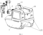
- an automatic driving and accurate positioning drilling robot is provided, referring to FIG. 1 to FIG. 12 .
- the automatic driving and accurate positioning drilling robot includes an unmanned ground vehicle 1, the unmanned ground vehicle 1 is a crawler-type electric carrying vehicle, a battery pack, driving motors and a control computer is arranged on the unmanned ground vehicle 1, the battery pack supplies power to the driving motor and the control computer, the control computer controls the driving motor to work, the driving motors include a forward-backward driving motor and a left-right turning motor, and a crawler belt is driven by the driving motors to move forwards and backwards and turn.
- a top portion of the unmanned ground vehicle 1 is provided with a laser radar 11 for drawing a map and navigation
- a front side and a rear side of the unmanned ground vehicle 1 are respectively provided with front ultrasonic sensors 12 and rear ultrasonic sensors 13 for perceiving and preventing collision
- the laser radar 11, the front ultrasonic sensors 12 and the rear ultrasonic sensors 13 are electrically connected to the control computer of the unmanned ground vehicle, respectively.
- the front ultrasonic sensors 12 are arranged on both sides of the front side of the unmanned ground vehicle 1
- the rear ultrasonic sensors 13 are arranged on both sides of the rear side of the unmanned ground vehicle 1.
- the four ultrasonic sensors are used for compensating a sensing blind area of the laser radar 11 during navigation, so as to prevent the front and rear sides of the unmanned ground vehicle 1 from hitting an obstacle.
- a manipulator 2 is arranged on the unmanned ground vehicle 1, and a percussion drill 3 is arranged on the manipulator 2.
- the manipulator 2 herein is a six-axis manipulator, has six degrees of freedom, and can rotate to any direction in space, thereby facilitating flexible drilling.
- the front side of the unmanned ground vehicle 1 is provided with a mounting platform 14 at a low position
- the rear side of the unmanned ground vehicle is provided with a navigation platform 15 at a high position
- the manipulator 2 is arranged on the mounting platform 14, and the laser radar 11 is arranged on the navigation platform 15.
- the mounting platform 14 is arranged to facilitate the manipulator 2 to touch a drilling position on the ground or a lower portion of a wall.
- the navigation platform 15 is arranged, so that the laser radar 11 has a wider sensing field of view.
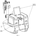
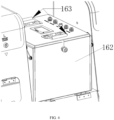
- the rear side of the unmanned ground vehicle 1 is provided with a detachable battery compartment 16, the battery compartment 16 is formed by two battery compartment covers 161 hinged to the unmanned ground vehicle 1, the battery compartment 16 is provided with a replaceable battery 162, and the replaceable battery 162 is provided with a handle 163, so as to facilitate removal of the replaceable battery 162.
- the percussion drill 3 is provided with a three-dimensional camera 31, and the three-dimensional camera 31 is used for finding a drilling position and a drilling angle, the three-dimensional camera 31 is electrically connected to the control computer of the unmanned ground vehicle 1 to transmit photographed three-dimensional information to the control computer.
- a rear side of the percussion drill 3 is provided with a force sensor 32, the force sensor 32 is used for sensing whether a steel bar is impacted during drilling, and the force sensor 32 is electrically connected to the control computer of the unmanned ground vehicle 1.
- the percussion drill 3 is further provided with a horizontal sensor 33 for feeding back an absolute vertical degree of the percussion drill relative to the earth, and the horizontal sensor 33 is electrically connected to the control computer of the unmanned ground vehicle 1.
- the unmanned ground vehicle 1 is provided with a WiFi communication module, a 4G/5G communication module, and an Internet networking module, and the WiFi communication module, the 4G/5G communication module, and the Internet networking module are all electrically connected to the control computer of the unmanned ground vehicle, so that the unmanned ground vehicle 1 can communicate with the outside in a WiFi communication, 4G/5G communication and Internet communication manner.
- the communication is to receive a control signal and transmit measured data of related sensors outwards.
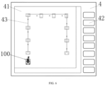
- the automatic driving and accurate positioning drilling robot further includes a human-computer interaction terminal 4 as shown in FIG. 6 , and the human-computer interaction terminal 4 is provided with a screen 41 and a plurality of manipulation buttons 42.
- a map of a drilling area of the robot 100 can be displayed on the screen 41.
- the map includes a drilling path 43 planned by the robot 100, and the human-computer interaction terminal 4 communicates with the control computer of the unmanned ground vehicle 1 in a WiFi communication, 4G/5G communication or Internet communication manner.
- the manipulation buttons 42 include, but are not limited to, a driving direction control button, a manipulator direction control button, a start drilling button, an emergency stop button, a shutdown button, and the like.
- the screen 41 is provided with a virtual button for adjusting drilling parameters, so that a drilling depth, a drilling size, a drill bit perpendicularity, and the like can be adjusted.
- the working principle of the automatic driving and accurate positioning drilling robot is as follows:
- the unmanned ground vehicle moves around the site.
- the laser radar on the robot continuously scans the site, and a map is constructed for the site in real time in cooperation with an SLAM map drawing algorithm.
- a drilling position in a design drawing (a CAD/BIM drawing) is input to the control computer of the robot, and then the scanning map and the input map are manually paired on a touch screen of the human-computer interaction terminal through translation, rotation, scaling and the like, and the input map is manually segmented if necessary, so as to pair the map part-by-part for positions most suitable for the action of each hole.
- Drilling path planning the control computer of the robot is provided with the SLAM map and design drawing fitting software.
- a drilling position in a drawing designed by BIM or CAD software can be calibrated on the SLAM map, and a drilling path and a parking operation position are automatically planned according to fitted drilling position coordinates and a design coverage range of a mechanical arm and laser radar vision.
- a user can also define a staying operation point and a staying angle of the robot, and the drilling path composed of a series of staying points through a software interface of the control computer of the robot.
- Drilling manner 1 after the robot automatically reaches an operation point, a drilling positioning of the mechanical arm is automatically calculated and adjusted based on drilling coordinates pre-imported by a control system in the robot, and drilling is implemented.
- drilling positions are paired according to drilling positions on a drilling path and according to a single working range of the robot, the drilling positions are combined into a plurality of drilling position combinations, a direction of a wall is determined according to a scanning of the laser radar and a building design drawing, and a stopping position at a fixed distance from the wall is calculated from the drilling position combination and the wall direction; and the shortest movement distance of the robot is found from the stopping position, so that a planned drilling path and a parking position are generated.
- the drilling path of the robot can also be modified by the user through the human-computer interaction terminal for adjustment. If needed, the user can also manually set the drilling path and the stopping position on the human-computer interaction terminal completely.
- an algorithm in the control computer perceives an obstacle in real time according to information of the laser radars and the short-distance ultrasonic sensors, and real-time adjustment of the path and obstacle avoidance are achieved.
- the whole process of the drilling operation of the robot is limited to a default drilling diameter, and if there are a plurality of drilling diameter requirements on one site, the drill bit needs to be replaced.
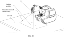
- Drilling manner 2 as shown in FIG. 10 , after a robot is automatically or manually controlled to reach a working point, the three-dimensional camera arranged on the mechanical arm detects a drilling position in a working range on the ground; if there is a default drilling positioning map, the relative coordinates in a visual range are fed back by the three-dimensional camera, and then drilling is implemented by the robot.
- the three-dimensional camera mounted on the manipulator of the robot may perform normal video streaming or photographing. Unlike a common camera, the three-dimensional camera may simultaneously output three-dimensional coordinates of each pixel in a photo to form a point cloud, which is used for perceiving a position in a three-dimensional space.
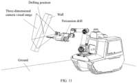
- the robot when the robot travels to a staying operation point according to the guidance of the control computer, because a three-dimensional map of the site, including the wall, has been stored in data of the robot through an SLAM map, the robot can appropriately adjust the manipulator, so that a three-dimensional camera and a percussion drill are oriented substantially perpendicular to the ground or the wall that needs to be drilled.
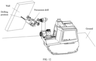
- the laser radar and the SLAM map drawing algorithm may have respective errors, the directions of the three-dimensional camera and the percussion drill may not be completely perpendicular to the wall. Therefore, as shown in FIG. 12 , before drilling by the drill bit of the percussion drill, the three-dimensional camera scans the ground or the wall of the drilling position coordinates in the robot data for calculating a direction difference between the wall and the percussion drill, and then adjusts a direction of the percussion drill through the manipulator, so that a direction error between the percussion drill and the wall is controlled within a certain range.
- the drilling position error is adjusted, it is not limited to an angle and a position of the wall shown in FIG. 11 and FIG. 12 .
- the robot can drill the wall at any angle.
- the manipulator can actually reach this position is defined as: when the manipulator moves to this position, a collision does not occur. For example, when the drilling position is under the ground, it is physically impossible for the manipulator to reach the underground for drilling, and this position is a position that cannot be actually reached.
- the horizontal sensor is suitable for use in underground drilling.
- the three-dimensional camera does not need to be used to adjust the direction of the percussion drill.
- the horizontal sensor on the manipulator may feed back an absolute vertical degree of the percussion drill relative to the earth.
- the robot can control the manipulator to fine-tune the angle, according to the feedback of the horizontal sensor, so that the percussion drill is turned back to be perpendicular.
- the robot controls the speed of the percussion drill according to the drilling setting (depth, size); and with reference to a drilling depth, the robot automatically calculates an appropriate speed to drill to the appropriate depth.
- the force sensor monitors the drilling force during drilling to determine whether there is a steel bar impacting.
- the determining method includes but is not limited to: a. sudden increase of the drilling force: when the drilling force increases suddenly, the percussion drill is still started, but the force does not decrease after stopping/slowly continuing to move into the hole for a period of time, it indicates that a steel bar is impacted.
- Battery replacement the battery is located at the rear of the robot, and after the compartment cover of the replaceable battery is opened, the battery can be pulled up by a handle as long as the main cable plug is unplugged, and another battery of the same model is replaced to supply power to the robot.
Landscapes
- Engineering & Computer Science (AREA)
- Mechanical Engineering (AREA)
- Robotics (AREA)
- Physics & Mathematics (AREA)
- General Physics & Mathematics (AREA)
- Radar, Positioning & Navigation (AREA)
- Remote Sensing (AREA)
- Aviation & Aerospace Engineering (AREA)
- Automation & Control Theory (AREA)
- Human Computer Interaction (AREA)
- Computer Networks & Wireless Communication (AREA)
- Optics & Photonics (AREA)
- Mining & Mineral Resources (AREA)
- Multimedia (AREA)
- Acoustics & Sound (AREA)
- Manipulator (AREA)
- Control Of Position, Course, Altitude, Or Attitude Of Moving Bodies (AREA)
Applications Claiming Priority (2)
| Application Number | Priority Date | Filing Date | Title |
|---|---|---|---|
| CN202223107944.8U CN219486175U (zh) | 2022-11-23 | 2022-11-23 | 一种自动驾驶、精确定位钻孔机械人 |
| PCT/CN2023/126629 WO2024109433A1 (fr) | 2022-11-23 | 2023-10-26 | Robot de forage à conduite autonome et positionnement précis |
Publications (2)
| Publication Number | Publication Date |
|---|---|
| EP4501568A1 true EP4501568A1 (fr) | 2025-02-05 |
| EP4501568A4 EP4501568A4 (fr) | 2025-11-19 |
Family
ID=87512070
Family Applications (1)
| Application Number | Title | Priority Date | Filing Date |
|---|---|---|---|
| EP23893524.1A Pending EP4501568A4 (fr) | 2022-11-23 | 2023-10-26 | Robot de forage à conduite autonome et positionnement précis |
Country Status (6)
| Country | Link |
|---|---|
| EP (1) | EP4501568A4 (fr) |
| JP (1) | JP3255779U (fr) |
| KR (1) | KR20250001105U (fr) |
| CN (1) | CN219486175U (fr) |
| CA (1) | CA3239696A1 (fr) |
| WO (1) | WO2024109433A1 (fr) |
Families Citing this family (4)
| Publication number | Priority date | Publication date | Assignee | Title |
|---|---|---|---|---|
| CN219486175U (zh) * | 2022-11-23 | 2023-08-08 | 智建机械技术有限公司 | 一种自动驾驶、精确定位钻孔机械人 |
| CN117921435A (zh) * | 2024-01-25 | 2024-04-26 | 中铁十一局集团有限公司 | 一种全自动打孔设备控制系统 |
| CN117921436A (zh) * | 2024-01-25 | 2024-04-26 | 中铁十一局集团有限公司 | 一种全自动打孔设备智能感应系统 |
| WO2026065714A1 (fr) * | 2024-09-24 | 2026-04-02 | 北京石头世纪科技股份有限公司 | Robot mobile et système de robot |
Family Cites Families (11)
| Publication number | Priority date | Publication date | Assignee | Title |
|---|---|---|---|---|
| CN106498834A (zh) * | 2016-12-30 | 2017-03-15 | 成都圭目机器人有限公司 | 一种履带轮道面修复机器人系统和道面修复方法 |
| JP6864319B2 (ja) * | 2017-03-13 | 2021-04-28 | 工建テック株式会社 | 連続削孔装置、及び、連続削孔方法 |
| CN107127731A (zh) * | 2017-05-16 | 2017-09-05 | 上海大界机器人科技有限公司 | 履带式自定位机器人多功能智能施工平台 |
| GB2582996B (en) * | 2019-07-01 | 2021-04-14 | A2E Industries Ltd | Vehicle, apparatus and method |
| CN110703778A (zh) * | 2019-10-12 | 2020-01-17 | 福州大学 | 矿山智能安全定位巡检机器人装置及系统 |
| GB2593501B (en) * | 2020-03-25 | 2024-06-05 | True Position Robotics Ltd | Robot drilling clamp |
| CN212706791U (zh) | 2020-07-17 | 2021-03-16 | 智建机械技术有限公司 | 一种自动定位钻孔及锚栓固定机器人 |
| CN112959518A (zh) * | 2021-03-04 | 2021-06-15 | 智建机械技术有限公司 | 一种建筑机器人 |
| CN113107358B (zh) * | 2021-04-26 | 2023-03-17 | 中国矿业大学 | 一种防冲击钻孔机器人及钻杆精确定位方法 |
| CN217345469U (zh) * | 2022-06-02 | 2022-09-02 | 王振杰 | 一种钻孔机器人 |
| CN219486175U (zh) * | 2022-11-23 | 2023-08-08 | 智建机械技术有限公司 | 一种自动驾驶、精确定位钻孔机械人 |
-
2022
- 2022-11-23 CN CN202223107944.8U patent/CN219486175U/zh active Active
-
2023
- 2023-10-26 CA CA3239696A patent/CA3239696A1/fr active Pending
- 2023-10-26 EP EP23893524.1A patent/EP4501568A4/fr active Pending
- 2023-10-26 JP JP2025600062U patent/JP3255779U/ja active Active
- 2023-10-26 WO PCT/CN2023/126629 patent/WO2024109433A1/fr not_active Ceased
- 2023-10-26 KR KR2020257000031U patent/KR20250001105U/ko active Pending
Also Published As
| Publication number | Publication date |
|---|---|
| KR20250001105U (ko) | 2025-07-15 |
| WO2024109433A1 (fr) | 2024-05-30 |
| EP4501568A4 (fr) | 2025-11-19 |
| JP3255779U (ja) | 2026-05-12 |
| CA3239696A1 (fr) | 2024-05-30 |
| CN219486175U (zh) | 2023-08-08 |
Similar Documents
| Publication | Publication Date | Title |
|---|---|---|
| CA3239696A1 (fr) | Robot de forage a conduite autonome et positionnement precis | |
| AU2013391114B2 (en) | Method and control system for a mining vehicle and a mining vehicle | |
| US20200399869A1 (en) | Image display system for work machine, remote operation system for work machine, and work machine | |
| JPWO2019189260A1 (ja) | ショベル | |
| JP7560973B2 (ja) | 掘削情報処理装置、作業機械、掘削支援装置および掘削情報処理方法 | |
| JP2020133223A (ja) | 安全装置及び建設機械 | |
| JP2016181119A (ja) | 移動機器の周囲状況提示システム | |
| KR20220131393A (ko) | 작업 기계 | |
| JPH0772472B2 (ja) | 地中掘削機の水平偏差測定装置 | |
| CN117355660A (zh) | 地下钻凿钻机行走控制 | |
| JP2022154674A (ja) | ショベル | |
| EP3978692B1 (fr) | Appareil de support de travail pour machine de travail | |
| JP2696442B2 (ja) | 自動法面掘削システム | |
| US20230272595A1 (en) | Remote control operation of a machine using a light beam for depth perception | |
| CN216696092U (zh) | 用于巷道盲区检测的设备 | |
| WO2002018749A1 (fr) | Appareil d'installation d'un ensemble support d'une structure rocheuse | |
| CN117083537A (zh) | 具有用于障碍物跟踪的自动相机控制的自行采掘机系统 | |
| US20250207369A1 (en) | Control system for excavator and excavator | |
| EP4394134B1 (fr) | Pelle pelle | |
| KR20260047246A (ko) | 전력 제어 시스템 및 전력 제어 방법 | |
| WO2026101427A1 (fr) | Robot de démolition et procédé d'exploitation d'un robot de démolition | |
| JPH0786768B2 (ja) | 無人走行車の走行制御装置 | |
| CN113686883A (zh) | 用于巷道盲区检测的设备及方法 | |
| WO2025047877A1 (fr) | Pelle excavatrice et système d'actionnement à distance pour pelle excavatrice | |
| JP2024175864A (ja) | 作業機械、及び作業機械の移動制御システム |
Legal Events
| Date | Code | Title | Description |
|---|---|---|---|
| STAA | Information on the status of an ep patent application or granted ep patent |
Free format text: STATUS: THE INTERNATIONAL PUBLICATION HAS BEEN MADE |
|
| PUAI | Public reference made under article 153(3) epc to a published international application that has entered the european phase |
Free format text: ORIGINAL CODE: 0009012 |
|
| STAA | Information on the status of an ep patent application or granted ep patent |
Free format text: STATUS: REQUEST FOR EXAMINATION WAS MADE |
|
| 17P | Request for examination filed |
Effective date: 20241101 |
|
| AK | Designated contracting states |
Kind code of ref document: A1 Designated state(s): AL AT BE BG CH CY CZ DE DK EE ES FI FR GB GR HR HU IE IS IT LI LT LU LV MC ME MK MT NL NO PL PT RO RS SE SI SK SM TR |
|
| STAA | Information on the status of an ep patent application or granted ep patent |
Free format text: STATUS: EXAMINATION IS IN PROGRESS |
|
| A4 | Supplementary search report drawn up and despatched |
Effective date: 20251020 |
|
| RIC1 | Information provided on ipc code assigned before grant |
Ipc: B28D 1/14 20060101AFI20251014BHEP Ipc: B28D 7/00 20060101ALI20251014BHEP Ipc: B25D 17/28 20060101ALI20251014BHEP Ipc: B25J 5/00 20060101ALI20251014BHEP Ipc: B25J 9/04 20060101ALI20251014BHEP Ipc: B25J 11/00 20060101ALI20251014BHEP Ipc: B25J 13/00 20060101ALI20251014BHEP Ipc: B25J 13/06 20060101ALI20251014BHEP Ipc: B25J 13/08 20060101ALI20251014BHEP Ipc: B25J 19/00 20060101ALI20251014BHEP Ipc: B25J 19/02 20060101ALI20251014BHEP Ipc: G05D 1/229 20240101ALI20251014BHEP Ipc: G05D 1/242 20240101ALI20251014BHEP Ipc: G05D 1/246 20240101ALI20251014BHEP Ipc: G05D 1/689 20240101ALI20251014BHEP Ipc: B23B 39/14 20060101ALI20251014BHEP Ipc: G05D 105/05 20240101ALN20251014BHEP Ipc: G05D 107/90 20240101ALN20251014BHEP Ipc: G05D 109/10 20240101ALN20251014BHEP Ipc: G05D 111/10 20240101ALN20251014BHEP Ipc: G05D 111/20 20240101ALN20251014BHEP |
|
| 17Q | First examination report despatched |
Effective date: 20251114 |
|
| DAV | Request for validation of the european patent (deleted) | ||
| DAX | Request for extension of the european patent (deleted) |