EP4501574A1 - System und verfahren zur handhabung von schaufelformen zur herstellung von windturbinenschaufeln - Google Patents
System und verfahren zur handhabung von schaufelformen zur herstellung von windturbinenschaufeln Download PDFInfo
- Publication number
- EP4501574A1 EP4501574A1 EP23189896.6A EP23189896A EP4501574A1 EP 4501574 A1 EP4501574 A1 EP 4501574A1 EP 23189896 A EP23189896 A EP 23189896A EP 4501574 A1 EP4501574 A1 EP 4501574A1
- Authority
- EP
- European Patent Office
- Prior art keywords
- framework
- blade
- hinge devices
- hinge
- mold
- Prior art date
- Legal status (The legal status is an assumption and is not a legal conclusion. Google has not performed a legal analysis and makes no representation as to the accuracy of the status listed.)
- Pending
Links
Images



Classifications
-
- B—PERFORMING OPERATIONS; TRANSPORTING
- B29—WORKING OF PLASTICS; WORKING OF SUBSTANCES IN A PLASTIC STATE IN GENERAL
- B29D—PRODUCING PARTICULAR ARTICLES FROM PLASTICS OR FROM SUBSTANCES IN A PLASTIC STATE
- B29D99/00—Subject matter not provided for in other groups of this subclass
- B29D99/0025—Producing blades or the like, e.g. blades for turbines, propellers, or wings
- B29D99/0028—Producing blades or the like, e.g. blades for turbines, propellers, or wings hollow blades
-
- B—PERFORMING OPERATIONS; TRANSPORTING
- B29—WORKING OF PLASTICS; WORKING OF SUBSTANCES IN A PLASTIC STATE IN GENERAL
- B29C—SHAPING OR JOINING OF PLASTICS; SHAPING OF MATERIAL IN A PLASTIC STATE, NOT OTHERWISE PROVIDED FOR; AFTER-TREATMENT OF THE SHAPED PRODUCTS, e.g. REPAIRING
- B29C31/00—Handling, e.g. feeding of the material to be shaped, storage of plastics material before moulding; Automation, i.e. automated handling lines in plastics processing plants, e.g. using manipulators or robots
- B29C31/006—Handling moulds, e.g. between a mould store and a moulding machine
-
- B—PERFORMING OPERATIONS; TRANSPORTING
- B29—WORKING OF PLASTICS; WORKING OF SUBSTANCES IN A PLASTIC STATE IN GENERAL
- B29C—SHAPING OR JOINING OF PLASTICS; SHAPING OF MATERIAL IN A PLASTIC STATE, NOT OTHERWISE PROVIDED FOR; AFTER-TREATMENT OF THE SHAPED PRODUCTS, e.g. REPAIRING
- B29C33/00—Moulds or cores; Details thereof or accessories therefor
- B29C33/20—Opening, closing or clamping
- B29C33/26—Opening, closing or clamping by pivotal movement
-
- B—PERFORMING OPERATIONS; TRANSPORTING
- B29—WORKING OF PLASTICS; WORKING OF SUBSTANCES IN A PLASTIC STATE IN GENERAL
- B29L—INDEXING SCHEME ASSOCIATED WITH SUBCLASS B29C, RELATING TO PARTICULAR ARTICLES
- B29L2031/00—Other particular articles
- B29L2031/08—Blades for rotors, stators, fans, turbines or the like, e.g. screw propellers
- B29L2031/082—Blades, e.g. for helicopters
- B29L2031/085—Wind turbine blades
-
- Y—GENERAL TAGGING OF NEW TECHNOLOGICAL DEVELOPMENTS; GENERAL TAGGING OF CROSS-SECTIONAL TECHNOLOGIES SPANNING OVER SEVERAL SECTIONS OF THE IPC; TECHNICAL SUBJECTS COVERED BY FORMER USPC CROSS-REFERENCE ART COLLECTIONS [XRACs] AND DIGESTS
- Y02—TECHNOLOGIES OR APPLICATIONS FOR MITIGATION OR ADAPTATION AGAINST CLIMATE CHANGE
- Y02P—CLIMATE CHANGE MITIGATION TECHNOLOGIES IN THE PRODUCTION OR PROCESSING OF GOODS
- Y02P70/00—Climate change mitigation technologies in the production process for final industrial or consumer products
- Y02P70/50—Manufacturing or production processes characterised by the final manufactured product
Definitions
- the present disclosure relates to wind turbine blades, and more particularly, to a system for handling blade molds during manufacturing of wind turbine blades.
- the disclosure further concerns a method used in the manufacturing of wind turbine blades.
- Wind turbines are commonly used to supply electricity into the electrical grid.
- Wind turbines of this kind generally comprise a tower and a rotor arranged on the tower.
- the rotor which typically comprises a hub and a plurality of blades, is set into rotation under the influence of the wind on the blades. This rotation generates a torque that is normally transmitted through a rotor shaft to a generator, either directly (in the case of “directly driven” or “gearless” wind turbines) or through the use of a gearbox. This way, the generator produces electricity which can be supplied to the electrical grid.
- the wind turbine hub may be rotatably coupled to a front of the nacelle.
- the wind turbine hub may be connected to a rotor shaft, and the rotor shaft may then be rotatably mounted in the nacelle using one or more rotor shaft bearings arranged in a frame inside the nacelle.
- the nacelle is a housing arranged on top of a wind turbine tower that may contain and protect the gearbox (if present) and the generator (if not placed outside the nacelle) and, depending on the wind turbine, further components such as a power converter, and auxiliary systems.
- wind turbine blades where each of the wind turbine blades are molded and assembled at the same workstation.
- the wind turbine blade may then be moved to another workstation, typically a finishing workstation, where the wind turbine blade is cut, trimmed, painted and the final fittings are mounted on the wind turbine blade.
- the wind turbine blades are often made of fiber-reinforced polymer and are usually manufactured as shell parts in molds, where the top side and the bottom side of the blade profile (typically the upwind or pressure side and the downwind or suction side, respectively) are manufactured separately by arranging glass fiber mats in each of the two molds and injecting a liquid resin, which subsequently is cured. Afterwards, the two halves are glued together, often by means of internal flange parts. Glue is applied to the inner face of the lower blade half before the upper blade half is lowered thereon or vice versa. Additionally, one or two reinforcing profiles (beams) are often attached to the inside of the lower blade half prior to gluing to the upper blade half. A crane or hoisting assembly may be used to lift one of the mold parts about a hinge line for closure and opening of the molds. Throughout this disclosure, a mold will primarily refer to each of the mold parts used for the manufacture of a blade shell part.
- the conventional manufacturing method requires that all the materials required for manufacturing a wind turbine blade, e.g. resin and fiber reinforcement material, be transported to every workstation, which is logistically demanding. Secondly, every workstation has to be equipped with tools necessary for every single manufacturing step in the process, which results in a significant overhead. Additionally, the usual manufacturing method requires a mold in every single workstation, which is expensive since production and maintenance of molds are time consuming and thus expensive. Furthermore, the conventional manufacturing method occupies a lot of space, and since the workers at each workstation have to perform a variety of manufacturing steps, there is a risk that the quality of the manufactured wind turbine blades may suffer.
- the materials required for manufacturing a wind turbine blade e.g. resin and fiber reinforcement material
- a specific logistic difficulty is associated with the manufacturing step of lifting one of the molds about a hinge for closure of the molds, i.e. for putting a mold containing a blade shell part on top of the other mold containing the other blade shell parts so that the blade parts can be fasted together. Due to the increasing size of the blades, this operation imposes a minimum building height which, based on the usual manufacturing method, results in a requirement to construct a manufacturing facility with a high ceiling at all workstations.
- EP2403708 proposes an alternative manufacturing method and an alternative manufacturing line involving "moving molds".
- a manufacturing line is disclosed, wherein wind turbine blades are formed in a number of mold sets, each of the mold sets comprising at least a first mold comprising a first mold cavity.
- the manufacturing line further comprises a number of separate workstations, where separate manufacturing steps are carried out. In particular, a sequence of steps in different workstations may be carried out to manufacture each of the blade shell parts. Once manufactured, the two blade shell parts are moved to a separate workstation where they are adhered to each other, e.g.
- wind turbine blades can be manufactured using fewer resources e.g. molds and tools, or alternatively improving the throughput as the method increases the number of manufactured wind turbine blades per time unit compared to conventionally project oriented manufacturing methods.
- each workstation can be equipped with specialized and advanced equipment that is dedicated to the manufacturing step carried out at each workstation. Additionally, each workstation can be manned with specialized workers that are skilled and trained in the manufacturing step carried out at that particular workstation, which lowers quality risks. However, some of the workstations can also be automated, e.g. by using robots, such that fewer workers are needed. Automation is also expected to additionally improve the quality of the manufactured wind turbine blades.
- US 9,796,116 discloses a transport vehicle for handling a rotor blade mold for the production of a rotor blade of a wind power installation or a shell portion of a rotor blade of a wind power installation, adapted for use in a handling apparatus.
- the handling apparatus includes a first rail set for displacement of the transport vehicle in a first direction, and a second rail set for displacement of the transport vehicle in a second direction.
- the transport vehicle includes a first wheel set including a plurality of wheels for movement on the first rail set, and a second wheel set including a plurality of wheels for movement on the second rail set.
- the handling apparatus can include a first rotor blade mold for the production of a first rotor shell portion and also a second rotor blade mold arranged on the transport vehicle for the production of a second rotor blade shell portion.
- the first rotor blade mold can be arranged to be stationary or can also be arranged on a transport vehicle.
- a hinge device adapted for pivotal movement of the second rotor blade mold, more specifically in such a way that a second rotor blade shell portion accommodated by the second rotor blade mold is pivoted on to a first rotor blade shell portion accommodated in the first rotor blade mold in order in that way to assemble those two rotor blade shell portions and to finish the rotor blade or to produce a corresponding sub-portion of the rotor blade.
- the hinge device is adapted to be fixedly but releasably connected to the second rotor blade mold for the pivotal movement.
- EP2403708 and US 9,796,116 disclose methods and systems which have important advantages over other prior art systems but further improvements are still welcome, in particular in terms of flexibility of the manufacturing line and the ability to handle different molds and the manufacture of different blades.
- a system for handling wind turbine blade molds includes a first framework configured to hold a first mold of one of an upwind and a downwind blade shell part of a wind turbine blade and a second framework configured to hold a second mold of the other of the upwind and the downwind blade shell part of the wind turbine.
- the system for handling wind turbine blade molds further comprises a set of one or more hinge devices, where the hinge devices comprise hinge connection interfaces configured to be releasably connected to corresponding framework connection interfaces of the first framework and to corresponding framework connection interfaces of the second framework.
- the system allows for a hinge system that, by virtue of being releasably connected to the two frameworks, can be used for multiple blade molds.
- the set of hinges may be arranged at a certain workstation of the manufacturing plant, where the hinge system can be releasably connected to a pair of frameworks for manufacturing a wind turbine blade when the frameworks are positioned in the corresponding workstation.
- the use of the same set of hinges i.e. the use of a shared hinge system, results in lower equipment costs.
- the use of a set of hinges that can be releasably connected to the respective frameworks provides increased flexibility in the manufacturing process as different frameworks, including frameworks supporting molds for manufacturing blades of different lengths, can be connected to the same hinge system.
- a method for manipulating molds during blade manufacturing comprises providing a first framework supporting a first mold containing a first shell part of a wind turbine blade and providing a second framework supporting a second mold containing a second shell part of a wind turbine blade.
- the method further comprises moving the first and second frameworks along a first direction, specifically a longitudinal direction of the blade, to a workstation, wherein the workstation comprises a set of one or more hinge devices.
- the first framework is releasably connected to a static member of the hinge devices whereas the second framework is releasably connected to a movable member of the hinge devices, the movable member being pivotable with respect to the static member about a substantially horizontal axis.
- the method further comprises using the hinge devices to pivot at least a part of the second framework so as to bring the second shell part into contact with the first shell part.
- the method allows the hinge system to remain in a specific workstation while the frameworks holding the molds with the blade shell parts are moved from previous workstations.
- a single dedicated position of the manufacturing plant may be used for the operation comprising closing the two molds containing the blade shell parts so that they can be glued and fastened together to manufacture a complete blade.
- the use of a dedicated workstation is also favoring the dedication of a specialist team, thus resulting in fewer defects and quicker operations.
- the frameworks are connected to the hinge system in a releasable manner. This results in a shared hinge system that can be used for multiple frameworks, including frameworks intended for production of different types of blades and, more particularly, for blades of varying lengths. This aspect is accordingly providing improved flexibility on the manufacturing plant while saving equipment costs.
- a longitudinal direction is to be interpreted as a direction along the length of the manufactured blade extending between the root and the tip, i.e. along the longitudinal axis of the blade.
- this direction is also the lengthwise direction of the molds used for the manufacture of blade shell parts or the lengthwise direction of the frameworks used to support the molds.
- a transverse direction is to be interpreted in this disclosure as a direction which is substantially horizontal and substantially perpendicular to the longitudinal direction, i.e. substantially perpendicular to the longitudinal axis of the blade.
- Fig. 1 illustrates a conventional modern upwind wind turbine 2 according to the so-called "Danish concept" with a tower 4, a nacelle 6 and a rotor with a substantially horizontal rotor shaft.
- the rotor includes a hub 8 and three blades 10 extending radially from the hub 8, each having a blade root 16 nearest the hub and a blade tip 14 furthest from the hub 8.
- Fig. 2 shows a schematic view of an example of a wind turbine blade 10.
- the wind turbine blade 10 has the shape of a conventional wind turbine blade with a root end 17 and a tip end 15 and comprises a root region 30 closest to the hub, a profiled or an airfoil region 34 furthest away from the hub and a transition region 32 between the root region 30 and the airfoil region 34.
- the blade 10 comprises a leading edge 18 facing the direction of rotation of the blade 10, when the blade is mounted on the hub, and a trailing edge 20 facing the opposite direction of the leading edge 18.
- the airfoil region 34 (also called the profiled region) has an ideal or almost ideal blade shape with respect to generating lift, whereas the root region 30 due to structural considerations has a substantially circular or elliptical cross-section, which for instance makes it easier and safer to mount the blade 10 to the hub.
- the diameter (or the chord) of the root region 30 may be constant along the entire root area 30.
- the transition region 32 has a transitional profile gradually changing from the circular or elliptical shape of the root region 30 to the airfoil profile of the airfoil region 34.
- the chord length of the transition region 32 typically increases with increasing distance from the hub.
- the airfoil region 34 has an airfoil profile with a chord extending between the leading edge 18 and the trailing edge 20 of the blade 10. The width of the chord decreases with increasing distance from the hub.
- a shoulder 40 of the blade 10 is defined as the position, where the blade 10 has its largest chord length.
- the shoulder 40 is typically provided at the boundary between the transition region 32 and the airfoil region 34.
- chords of different sections of the blade normally do not lie in a common plane, since the blade may be twisted and/or curved (i.e. pre-bent), thus providing the chord plane with a correspondingly twisted and/or curved course, this being most often the case in order to compensate for the local velocity of the blade being dependent on the distance to the hub.
- the wind turbine blade 10 comprises a blade shell comprising two blade shell parts or half shells, a first blade shell part 24 and a second blade shell part 26, typically made of fiber-reinforced polymer.
- the wind turbine blade 10 may comprise additional shell parts, such as a third shell part and/or a fourth shell part.
- the first blade shell part 24 is typically a pressure side or upwind blade shell part.
- the second blade shell part 26 is typically a suction side or downwind blade shell part.
- the first blade shell part 24 and the second blade shell part 26 are fastened together with adhesive, such as glue, along bond lines or glue joints 28 extending along the trailing edge 20 and the leading edge 18 of the blade 10.
- the root ends of the blade shell parts 24, 26 has a semi-circular or semi-oval outer cross-sectional shape.
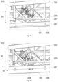
- Figure 3A and 3B show an area of a manufacturing line 99 for manufacturing a wind turbine blade 10 according to an example.
- a first workstation 95 and a second workstation 96 are shown, wherein the second workstation 96 comprises a set 300 of hinge devices 301a - 301d.
- the number and location of the hinge devices 301a-301d may vary in different examples and, particularly, they may depend on the characteristics (e.g. length), of the manufactured blade.
- the hinge devices 301a-301d may comprise a support configured to rest on a floor of the workstation.
- a first blade shell part corresponding to either the upwind or downwind part of a wind turbine blade 10 may be contained in a first mold 103, which is supported by a first framework 100.
- a second blade shell part corresponding to the other of the upwind and downwind part of a wind turbine blade 10 may be contained on a second mold 203, which is supported by a second framework 200.
- the manufacturing step at workstation 95 may comprise infusion of matrix material, thus forming separate blade shell parts and, more particularly, an upwind and a downwind blade shell part of the same blade. Curing of the resin may take place at workstation 95 but this is not necessary.
- further workstations where further manufacturing steps take place may be arranged upstream from the workstation 95, e.g. a gelcoat station and/or a fiber lay-up station.
- the first framework 100 and the second framework 200 are movable in a longitudinal direction corresponding substantially to a lengthwise direction of the blade shell parts according to an example.
- Figures 3A and 3B illustrate the move of the first framework 100 and the second framework 200 from the first workstation 95 to the second workstation 96. The move takes place in the longitudinal direction 91, i.e. along the lengthwise direction of the axis of the blade shell parts.
- a number of rails 90 may be provided on the floor of the assembly plant.
- Workstation 96 comprises a set 300 of hinge devices 301a-301d.
- Figure 3B schematically illustrates the releasable connection of both the first framework 100 and the second framework 200 to each of the hinge devices 301a-301d.
- the hinge devices 301a - 301d may be arranged in holding or supporting structures in the workstation 96. Such holding or supporting structures may be supported, i.e. resting, on the floor of the workstation.
- the manufacturing step at workstation 96 corresponds to the closing of the molds.
- the hinge devices 301a-301d may be used to lift and turn at least a part of one of the first framework 100 and the second framework 200 so that the corresponding blade mold (103 or 203 respectively) is repositioned into a so-called closed mold position such that it is arranged on top of the other blade mold.
- the two blade shell parts contained in the corresponding molds are put into contact and they are fastened together, e.g. by gluing.
- Suitable glue may be applied to portions of the shells prior to complete closing of the mold.
- Glue may also be applied to e.g. internal reinforcement structures such as spars.
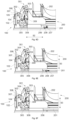
- FIGS 4A - 4C illustrate an example of a system for handling wind turbine blade molds during blade manufacturing. Different stages of the manufacturing sequence, all of them occurring at the same workstation, are illustrated in each of the figures.
- Figure 4A shows a first framework 100 for supporting a first mold 103 and a second framework 200 for supporting a second mold 203.
- At least one of the frameworks may comprise a bed frame and a mold frame releasably mounted on the bed frame.
- the first framework 100 comprises a first bedframe 101 and a first mold frame 102 to support a first mold 103
- the second framework 200 comprises a second bedframe 201 and a second mold frame 202 for supporting a second mold 203.
- first framework 100 and the second framework 200 in this example each comprise a first set of wheels to move in the longitudinal direction.
- the bedframe 101 of the first framework 100 comprises a set of wheels that facilitate the movement of the first framework 100 along the rails 90, i.e. in a longitudinal direction 91.
- the first mold 103 may be containing either the downwind or the upwind blade part of a wind turbine blade.
- the second mold 203 is containing the other of the upwind and downwind blade part.
- the second framework 202 in this example is also movable in the longitudinal direction 91 and, to this end, a first set of wheels 206 for the second bedframe 201 is arranged.
- Rails 90 may be used to facilitate the move of the frameworks and, more particularly, to increase safety of the operations by preventing deviations from established maneuvers. Nevertheless, systems with no such rails may be also provided. Different types of rails 90 may be implemented. In particular, rails 90 may comprise longitudinal grooves practiced on the floor of the manufacturing plant or they may also comprise horizontal bars fixed on the floor. It should be clear that alternatives to wheels such as skates, slides, rollers or other may be used for moving the frameworks and molds in other examples.
- a set 300 of four hinge devices 301a-301d is disposed in between the two frameworks as also shown in Figure 4A .
- the hinge devices 301a-301d comprise connection interfaces configured to be releasably connected to corresponding connection interfaces of the first 100 and second 200 frameworks. More details regarding structural characteristics and operation of the connection interfaces will be provided with reference to Figures 5A-5B and Figures 6A-6G .
- a set of four hinge devices 301a-301d is shown but any number of hinge devices may be used depending, among other aspects, on the length of the frameworks, which may depend on the length of the manufactured blade.
- the first framework 100 is aligned with the set 300 of hinge devices 301a-301d both in the longitudinal 91 and transverse 92 directions.
- the connection interfaces of the framework 100 and hinge devices 301a-301d are in position for engagement in those directions.
- the second framework 200 which is positioned in the corresponding rails 90, is also aligned with the hinge devices 301a-301d in the longitudinal direction 91, i.e. the connection interfaces of the framework 200 are at the same position in the longitudinal direction 91 as the connection interfaces of the hinge devices 301a-301d, but it is separated from the hinge devices 301a-301d in the transverse direction 92.
- the relative alignment of the first 100 and second 200 framework with respect to the set 300 of hinge devices may be different, e.g., both frameworks 100, 200 may be spaced from the set 300 of hinge devices in the transverse direction 92, both frameworks 100, 200 may be aligned with the hinge devices 301a-301d, or the first framework 100 may be the one spaced apart in the transverse direction 92 whereas the second framework 200 is aligned.
- At least one of the first framework 100 and the second framework 200 may be movable in a transverse direction 92, i.e. in a direction substantially perpendicular to the lengthwise direction of the framework. This transverse movement is visible in Figure 4B , which shows a subsequent stage in the manufacturing sequence according to an example.
- Figure 4B depicts the situation where both the first framework 100 and the second framework 200 have been connected to the hinge devices 301a-301d. More details will be provided below but Figure 4B shows that, in order to enable said connection, the second framework 200 moves laterally along the direction 92 so that the connection with the hinge devices 301a-301d is enabled. In particular, Figure 4B shows that the second framework 200 is no longer resting on the rails 90 with its first set of wheels 206, which are now lifted and no longer touching the floor and supporting the framework 200, but arranged within connecting distance of the hinge devices 301a-301d. As also visible in Figure 4B , the hinge devices 301a-301d are displaced vertically downwards with respect to their position in Figure 4A to enable the connection. More details about the functionality of the hinge devices 301a-301d will be provided with reference to Figures 5A - 5B and Figures 6A - 6G .
- Figure 4C shows a further step in the manufacturing sequence occurring in the same workstation.
- This step corresponds to the closing of the blade mold, i.e. to the situation where one of the molds is positioned on top of the other mold.
- Hinge devices 301a-301d are shown in an extended position which, in this example, results in the mold frame 202 of the second framework 200 being tilted and resting on the mold frame 102 of the first framework 100.
- the blade shell part contained on the second mold 203 (not visible) is brought into contact with the blade shell part contained on the first mold 103 so that the two shell parts can be joined together.
- the mold frame 202 of the second framework 200 is tilted while the bedframe 201 of the second framework 200 remains on the floor.
- FIG. 4C Also depicted in Figure 4C are some components of the moving system 207.
- the moving system 207 is used in an example to lift the second framework 200 and to displace the second framework 200 in the transverse direction to bring it in close proximity of the hinge devices 301a-301d. Details regarding the moving system 207 and its operation will be provided below.
- FIGS 5A and 5B schematically illustrate an example of a hinge device 301 and its connection with both the first framework 100 and the second framework 200.
- the hinge device 301 comprises a static first member 302 connectable to the first framework 100 and a movable second member 303 connectable to the second framework 200, the movable second member 303 being arranged to pivot with respect to the static first member 302 about a substantially horizontal axis (defined in this example by a pivot point for horizontal rotation 304) so that at least a part of the second framework 200 (in particular, the second mold frame 202 in this example) can be rotated such that a mold held by the second framework 200 can be brought into contact with a mold held by the first framework so as to form a complete wind turbine blade.
- a turning or pivoting mechanism 309 of the hinge device 301 is also shown.
- a hydraulic cylinder is used as a turning mechanism 309 although other options, such as an electromechanical actuator, may be available.
- the hinge device 301 may be passive, thus providing a pivot point about the horizontal axis 304 but not comprising a turning mechanism 309. In those cases, a crane or similar hoisting equipment may be used to turn the second framework 200 (or part of it) about the pivot point 304.
- the second member 303 of the hinge device is connectable to a mold frame 202 of the second framework 200 so that only the mold frame is lifted and pivoted whereas the bed frame 201 is arranged to remain on the floor. In this manner, only the relevant equipment needs to be lifted and tilted.
- the hinge devices may comprise connection interfaces 306, 307, 308 configured to be releasably connected to corresponding connection interfaces 104, 105 of the first framework 100 and to corresponding connection interfaces 204 of the second framework 200.
- connection interfaces may in some examples comprise one or more hooks in one of the hinge devices and the corresponding framework configured to engage with connection pins of the other of the hinge device and the corresponding framework.
- the hinge connection interfaces may further comprise a locking mechanism, specifically comprising a hydraulic pin on the hinge device arranged to engage with a pad eye on the corresponding framework.
- connection interfaces on the static member 302 of the hinge device 301 comprise a hook system 306 with a number of hooks, which in this example are arranged at two different heights. and which is intended to engage with a connection interface in the first mold frame 102 of the first framework 100 which, in this example, comprises connecting pins 104 arranged at two different heights to match the different heights of the hook system 306.
- the hinge connection interface in this example comprises also a locking mechanism which is embodied as a hydraulic pin 307 in the static member 302 of the hinge device 301 which is arranged to engage a pad eye 105 in the mold frame 102 once the two parts are properly engaged.
- connection interfaces are shown in Figure 5A for the releasable connection between the movable member 303 of the hinge device 301 and the mold frame 202 of the second framework 200.
- a hook system 204 is arranged on the mold frame 202 which is intended for connection with the connecting pins 308 in the movable member 303 of the hinge device 301.
- the hooks are configured to engage with and hook over connecting pins 308.
- Figure 5A illustrates the situation before connection whereas Figure 5B illustrates the situation upon connection.
- Figure 5B shows the hook system 306 of the static member 302 already engaged with the connecting pins 104 of the first mold frame 102.
- the locked status of this connection is shown by the locking pin 307 being engaged with the pad eye 105.
- the releasable connection between the movable member 303 of the hinge device 301 and the second mold frame 202 is also established in Figure 7B .
- the hook system 204 of the second mold frame 202 is shown in an engaged position with respect to the connecting pins 308 of the movable member 303.
- An example may provide for the hinge devices, and particularly the supports of the hinges, to be movable in the vertical direction, specifically by means of a hydraulic system, so that they can be releasably connected to the first framework and to the second framework at various positions.
- Figures 5A and 5B illustrate the hinge device 301 at two different heights, i.e. at different positions along the vertical direction 93.
- Figure 5A shows a situation when the hinge device 301 is not yet connected to the first mold frame 104 and second mold frame 202, in which case a lifting device 305, specifically in this case a hydraulic system, is depicted in a first, extended, position.
- a lifting device 305 specifically in this case a hydraulic system
- FIG 5B illustrates the connected situation, when the hinge device 301 is connected to both the first mold frame 102 and the second mold frame 202.
- the hinge device 301 is shown as being arranged at a different height. More particularly, the lifting device 305 is actuated so that the hinge device 301 is lowered.
- the use of the lifting device 305 allows then vertical displacement of the hinge device 301 which may be useful to facilitate connection to a certain framework (see Figures 6A-6G ) and/or to enable connection of the same hinge device 301 to different frameworks, e.g. frameworks intended for the manufacture of different types of blades which may require connection at different positions in the vertical direction 93.
- a plurality of hinge devices may be distributed in the longitudinal direction defined by the length of the first 100 and second 200 framework so that the connection interfaces of each of the hinge devices is faced with a corresponding connection interface of a plurality of connection interfaces of each of the first and second frameworks. This is illustrated by, e.g. Figures 4A-4B and by Figures 5A-5B .
- FIGS 4A-4C illustrate a system with four hinge devices 301a-301d distributed along the length of the first framework 100 and the second framework 200.
- Each of those hinge devices 301a-301d comprises some connection interfaces, which are aligned with corresponding connection interfaces of the first and second framework, i.e. the connection interfaces are at the same position along the longitudinal direction 91 so that connection interfaces of the hinge devices face connection interfaces of the frameworks.
- the specific characteristics of the connection interfaces are further shown in Figures 5A-5B , which provide an example of a single hinge device 301, whose different connection interfaces 306, 307, 308 are aligned with, i.e. faced, with the connection interfaces of the first framework 104, 105 and with the connection interfaces 204 of the second framework 202 in the longitudinal direction.
- each of the hinge devices 301a-301d may be movable in the longitudinal direction. In this manner, increased flexibility for the process is achieved. Said movement may be used to adjust the position of the same set of hinge devices 300 to different frameworks or to correct the relative position of the connection interfaces in case of slight deviations.
- rails may be provided for the displacement of the hinge devices 301a-301d.
- the hinge devices 301a-301d may be arranged with their supports on said rails and movement of the hinge devices may be facilitated by a spindle driven by a servo motor which may displace the hinge device along the rails.
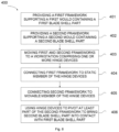
- the method 400 comprises, at block 401, providing a first framework supporting a first mold containing a first blade shell part of a wind turbine blade and, at block 402, providing a second framework supporting a second mold containing a second blade shell part of a wind turbine blade.
- the method 400 comprises, at block 403, moving the first and second frameworks along a first direction, specifically a longitudinal direction, to a workstation, wherein the workstation comprises one or more hinge devices.
- the method 400 comprises connecting the first framework to a static member of the hinge devices and block 405 comprises connecting the second framework to a movable member of the hinge devices, the movable member being pivotable with respect to the static member about a substantially horizontal axis
- the method further comprises, at block 406, using the hinge devices to pivot at least a part of the second framework so as to bring the second blade shell part into contact with the first blade shell part.
- Connecting the first framework to a static member of the hinge devices or connecting the second framework to a movable member of the hinge devices may further comprise aligning the respective framework with the hinge devices so that connection interfaces of the respective framework are at the same longitudinal position as corresponding connection interfaces of the hinge devices.
- the method in another example may comprise, in order to connect the first framework to a static member of the hinge devices or in order to connect the second framework to a movable member of the hinge devices, vertically displacing at least one of the hinge devices with a lifting device and the respective framework with a moving system.
- the method according to another example may also comprise moving at least one of the first framework and the second framework in a transverse direction when connecting the first framework to the static member of the hinge devices or when connecting the second framework to a movable member of the hinge devices.
- This method allows increased flexibility of the system by providing an additional degree of freedom in the movement of the frameworks.
- a moving system may be used to displace the respective framework in the vertical direction and in the transverse direction.
- two different systems may be used to displace the framework in either the vertical or the transverse direction.
- connecting a second framework to a movable member of the hinge devices may comprise connecting a mold frame support of the second framework to the movable member of the hinge devices and it may further comprise releasing the mold frame from a bed frame before actuation the hinge devices so that only the mold frame with the second blade shell is pivoted upon actuation of the hinge devices. In this manner, only the required equipment is tilted which may facilitate the operation while reducing costs.
- Figures 6A - 6G schematically illustrate a method of manipulating molds during a blade manufacturing process. More particularly, these figures provide a sequence of an example of the releasable connection of a hinge device 301 to both a first mold frame 102 and a second mold frame 202.
- a hinge device 301 is aligned, i.e. facing, a first mold frame 102 and a second mold frame 202.
- the static member 302 of the hinge device 301 is facing the first mold 102 whereas the movable member 303 of the hinge device 301 is facing the second mold frame 202.
- the connection interfaces 306, 307 of the static member 302 of the hinge device 301 are aligned with the connecting pins 104 of the first mold frame 102 in the first direction 91, i.e. they are facing each other.
- the same connection interfaces are also aligned in the transverse direction 92.
- connection interfaces are at a different height, i.e. the hook system 306 of the static member 302 of the hinge device 301 is at a higher vertical position than the receiving connecting pins 104 of the first mold frame 102. Consequently, releasable connection has not occurred yet.
- the connecting pins 308 on the movable part 303 of the hinge device 301 and the hook system 204 of the second frame 202 are located at the same position along the longitudinal direction 91 but they are at different heights in the vertical direction 93 and also at different positions in the transverse direction 92.
- the static member 302 of the hinge device 301 is engaged with the mold frame 102 of the first framework 100.
- a lifting device 305 of the hinge device 301 may be provided.
- the lifting device 305 e.g. a hydraulic system, is actuated so that the hinge device 301 is lowered in the vertical direction 93 from the situation previously depicted in relation to Figure 6A until the hook system 306 of the static member 302 engages the connecting pins 104 of the first mold frame 102.
- the locking mechanism is actuated so that the locking pin 307 is passed through the eye pad 105.
- Figures 6C-6E show a sequence for engagement between the connection interfaces of the movable member 303 of the hinge device 301 and the connection interfaces of the second mold frame 202.
- the connecting pins 308 of the movable member 303 are aligned with the hook system 204 of the second mold frame 202 in the longitudinal direction 91 but they are at a different position in the transverse direction 92.
- the hooking system 204 is at the same position in the vertical direction 93 as the connecting pins 308 but, as also deductible from previous Figure 6B , the second mold frame 202 may be lifted so that the hook system 204 can be arranged above the connecting pins 308 by displacing the second mold 203 in the transverse direction 92 and then lowered for engagement. Consequently, a first upward vertical movement, i.e. a movement along direction 93, followed by a transverse movement along direction 92, and finally, a downward vertical movement along direction 93 may be used to connect the movable part 303 of the hinge device 301 with the second mold frame 202.
- At least one of the first framework and the second framework may be movable in a transverse direction of the first and the second framework.
- the first of second framework may engage a moving system comprising a second set of wheels arranged substantially in the transverse direction.
- Such moving system may also be configured to lift the at least first and second framework from the floor in an upward direction so that the second set of wheels supports the framework while allowing displacement of the framework in the transverse direction.
- the moving system may comprise a hydraulic piston configured to push the at least first or second framework in a vertically upwards direction while the second set of wheels rests on the floor.
- Figure 6C depicts such a moving system 207 which, in this example, is attached to the bed frame 201 of the second framework 200.
- the second framework 200 which includes the second bed frame 201 and the second mold frame 202, is lifted from the floor in a vertical direction 93.
- the second framework 200 is no longer supported by the first set wheels 206 but by a second set of wheels 208.
- the first set of wheels 206 is configured to run in the longitudinal direction 91 whereas the second set of wheels 208 is oriented in the transverse direction 92.
- the second framework 200 may be moved in the transverse direction 92 with the aid of the second set of wheels 208 toward the hinge device 301 so that the hook set 204 of the second mold frame 202 and the connecting pins 308 of the movable member 303 of the hinge device 301 are in the same position in the transverse direction 92.
- This situation is schematically illustrated in Figure 6D .
- a similar situation to that depicted in Figure 6A for the connection of the first mold frame 102 and the static member 302 of the hinge device is also observed here.
- connection interfaces of the second mold frame 202 and of the movable member 303 of the hinge device 301 are aligned in both the longitudinal direction 91 and the transverse direction 92 but they are at different positions, i.e. heights, in the vertical direction 93.
- the moving system 207 which was already used to move the second framework 200 in the transverse direction 92, is used to lower the framework 200 (and so the second mold frame 202) along the vertical direction 93 until the hook set 204 is engaged with the connecting pins 308 of the movable member 303 of the hinge device 301.
- the second framework 200 is still supported by the second set of wheels 208 of the moving system 207 and not by the first set of wheels 206, which is still slightly above the floor.
- a locking pin or a similar system may be used to lock the parts so as to prevent any accidental movement.
- the hinge device 301 is releasably connected to both the first framework 100 and the second framework 200. More particularly, the static member 302 of the hinge device 301 is connected to the first mold frame 102 of the first framework 100 and the movable member 303 of the hinge device 301 is connected to the second mold frame 202 of the second frame 200.
- Figure 6F shows a subsequent situation in an example which, in this case, comprises decoupling the second mold frame 202 from the second bed frame 201.
- the releasable connection between the mold frame 202 and the bed frame 201 (not shown in the figure) is released and the bed frame 201 is lowered by retracting the moving system 207 so that the first set of wheels 206 is again in contact with the floor and supporting the bed frame 201.
- the second mold frame 202 and the corresponding second mold 203 containing the blade shell part may be supported by the connection interface with the movable member 303 of the hinge device 301.
- a turning mechanism more specifically a hydraulic cylinder of the hinge devices, is used to pivot at least a part of the second framework so as to bring the second blade shell part into contact with the first blade shell part.
- the turning mechanism 309 of the hinge device 301 is actuated so that the movable part 303 of the hinge device 301, which is connected to the second mold frame 202, rotates about the pivot point for horizontal rotation 304 thus bringing the second blade shell part arranged in the second mold 203 (not shown in the figure) into contact with the first blade shell part arrange in the first mold 103 (not shown in the figure) to close the mold.
- the first framework 100 may act as the anchor for the hinge devices 301a-301d, so that the hinge devices 301a-301d may be only supported but not fixed to the floor. In this manner, the floor does not need to be reinforced to absorb the turning torque.
- Figures 7A - 7B show an enlarged view of the moving system 207 engaged with the second bed frame 201 of the second framework 200.
- Figure 7A corresponds to the situation where the moving system 207 is not operating, i.e. the bed frame 201 is supported by the first set of wheels 206 and the moving system 207, which comprises a hydraulic piston 209, is in a retracted position. Accordingly, the second set of wheels 208 is not in contact with the floor and the second framework 200 is able to move with the aid of the first set of wheels 206 in the longitudinal direction 91 along the rails 90.
- Figure 7B shows the situation when the moving system 207 is in its extended position.
- the hydraulic piston 209 is actuated, which results in the second set of wheels 208 been projected from its original retracted position.
- the second framework 200 is pushed upwards in the vertical direction 93. Consequently, the first set of wheels 206 is no longer in contact with the floor and the second framework 200 is now supported by the second set of wheels 208 which, in this example, is oriented in the traversal direction 92, i.e. in a direction substantially perpendicular to the longitudinal direction of the second framework 200.
- the moving system 207 in this example comprises a hydraulic piston 209 as actuation mechanism. Nevertheless, other actuators, such as electromechanical systems, may be also used in alternative examples.
- the moving system 207 in this example facilitates movement of the second framework 200 in two different directions.
- actuation of the hydraulic piston 209 allows moving the framework 200 in a vertical direction 93.
- a second set of wheels 208 is used, movement in the direction of that set of wheels is also facilitated.
- the direction of the second set of wheels 208 coincides with the transverse direction 92.
- other examples may comprise wheels oriented in different directions.
- the orientation of the wheels in the moving systems may be adjusted by means of an internal mechanism.
- multiple moving systems comprising different sets of wheels oriented at different orientations, may be engaged with the framework and they may be selectively actuated so that the second framework becomes supported by a set of wheels with a certain preferred orientation aimed at facilitating move of the framework in certain directions.
- an example method may further comprise attaching the first blade shell contained in the first mold 103 part of the blade and the second blade shell part contained in the second mold 203 so as to form a single blade.
- the method may further comprise actuating the hinge devices 301 to pivot the at least part of the second framework 200 back to its non-tilted position.
- the method may comprise moving the first framework 100 and/or the second framework 200 to a different workstation.
- a reverse sequence to the one described with reference to figures 6A to 6F may be used to release the connections between the set 300 of hinge devices 301 and both the first mold frame 102 and the second mold frame 202.
- the first framework 100 and the second framework 200 may be movable in the longitudinal direction 91 by means of the corresponding sets of first wheels 106 or 206.
- a moving system 207 may be used to displace the corresponding framework in a non-longitudinal direction and, more particularly, on a transverse direction 92.
- any of the frameworks may be positioned in a different workstation to continue with a next manufacturing step of the blade. This may be the situation if, following with the example shown in reference to Figures 6A-6G , the first framework 100 containing now the blade shell parts is moved.
- the next workstation may comprise an initial manufacturing step for a new wind turbine blade. This may be the situation if, following with the example shown in reference to Figures 6A-6G , the second framework 200, which in the example is no longer carrying a blade shell part at the end of the sequence, is moved.
Landscapes
- Engineering & Computer Science (AREA)
- Mechanical Engineering (AREA)
- Robotics (AREA)
- Wind Motors (AREA)
Priority Applications (1)
| Application Number | Priority Date | Filing Date | Title |
|---|---|---|---|
| EP23189896.6A EP4501574A1 (de) | 2023-08-04 | 2023-08-04 | System und verfahren zur handhabung von schaufelformen zur herstellung von windturbinenschaufeln |
Applications Claiming Priority (1)
| Application Number | Priority Date | Filing Date | Title |
|---|---|---|---|
| EP23189896.6A EP4501574A1 (de) | 2023-08-04 | 2023-08-04 | System und verfahren zur handhabung von schaufelformen zur herstellung von windturbinenschaufeln |
Publications (1)
| Publication Number | Publication Date |
|---|---|
| EP4501574A1 true EP4501574A1 (de) | 2025-02-05 |
Family
ID=87557579
Family Applications (1)
| Application Number | Title | Priority Date | Filing Date |
|---|---|---|---|
| EP23189896.6A Pending EP4501574A1 (de) | 2023-08-04 | 2023-08-04 | System und verfahren zur handhabung von schaufelformen zur herstellung von windturbinenschaufeln |
Country Status (1)
| Country | Link |
|---|---|
| EP (1) | EP4501574A1 (de) |
Citations (3)
| Publication number | Priority date | Publication date | Assignee | Title |
|---|---|---|---|---|
| EP2403708A1 (de) | 2009-03-06 | 2012-01-11 | LM Glasfiber A/S | Verfahren und fertigungsstrasse zur herstellung von windturbinenschaufeln |
| CN205615027U (zh) * | 2016-05-20 | 2016-10-05 | 上海华宜风电模具有限公司 | 一种风电叶片模具翻转系统 |
| US9796116B2 (en) | 2012-07-02 | 2017-10-24 | Wobben Properties Gmbh | Handling device for handling a rotor blade mold for producing a rotor blade of a wind turbine |
-
2023
- 2023-08-04 EP EP23189896.6A patent/EP4501574A1/de active Pending
Patent Citations (3)
| Publication number | Priority date | Publication date | Assignee | Title |
|---|---|---|---|---|
| EP2403708A1 (de) | 2009-03-06 | 2012-01-11 | LM Glasfiber A/S | Verfahren und fertigungsstrasse zur herstellung von windturbinenschaufeln |
| US9796116B2 (en) | 2012-07-02 | 2017-10-24 | Wobben Properties Gmbh | Handling device for handling a rotor blade mold for producing a rotor blade of a wind turbine |
| CN205615027U (zh) * | 2016-05-20 | 2016-10-05 | 上海华宜风电模具有限公司 | 一种风电叶片模具翻转系统 |
Similar Documents
| Publication | Publication Date | Title |
|---|---|---|
| CN104093546B (zh) | 用于制造风轮机叶片的系统及方法 | |
| US20210231097A1 (en) | A system and method for manufacturing a wind turbine blade | |
| US11794379B2 (en) | Turning system for wind turbine blade parts | |
| US10328640B2 (en) | Wind turbine blade manufacturing system and method | |
| EP3257646A1 (de) | Schaufelform zur herstellung eines schaufelhüllenteils einer windturbinenschaufel und zugehöriges verfahren | |
| US20240181732A1 (en) | Pneumatically operated web lifting tongs | |
| EP3723972B1 (de) | System und verfahren zur herstellung einer verstärkten windturbinenschaufel | |
| EP4501574A1 (de) | System und verfahren zur handhabung von schaufelformen zur herstellung von windturbinenschaufeln | |
| EP4563338A1 (de) | System und verfahren zur scherstegbefestigung in windturbinenschaufeln | |
| EP4571096A1 (de) | System und verfahren zur herstellung von windturbinenschaufeln | |
| EP4571095A1 (de) | System und verfahren zur herstellung von windturbinenschaufeln | |
| EP4501573A1 (de) | Bewegliche plattform und verfahren zur handhabung einer beweglichen plattform zur herstellung von windturbinenschaufeln | |
| EP4234918B1 (de) | Verfahren zur blattwurzelentovalisierung und anordnungen dafür | |
| EP4609989A1 (de) | Bearbeitung eines wurzelteils einer windturbinenschaufel | |
| EP4506146A1 (de) | Formanordnungen und verfahren bei der herstellung von windturbinenschaufeln | |
| EP4290073A1 (de) | Werkzeuge zur lagerung von windturbinenschaufeln | |
| EP4265906A1 (de) | Träger zum drehen eines verbundteils und zugehörige verfahren | |
| WO2025068716A1 (en) | Apparatus and method for use in wind blade assembly | |
| CN121816257A (zh) | 在叶片模具中定位翼梁帽 |
Legal Events
| Date | Code | Title | Description |
|---|---|---|---|
| PUAI | Public reference made under article 153(3) epc to a published international application that has entered the european phase |
Free format text: ORIGINAL CODE: 0009012 |
|
| STAA | Information on the status of an ep patent application or granted ep patent |
Free format text: STATUS: THE APPLICATION HAS BEEN PUBLISHED |
|
| AK | Designated contracting states |
Kind code of ref document: A1 Designated state(s): AL AT BE BG CH CY CZ DE DK EE ES FI FR GB GR HR HU IE IS IT LI LT LU LV MC ME MK MT NL NO PL PT RO RS SE SI SK SM TR |
|
| STAA | Information on the status of an ep patent application or granted ep patent |
Free format text: STATUS: REQUEST FOR EXAMINATION WAS MADE |
|
| 17P | Request for examination filed |
Effective date: 20250805 |