EP4501595A1 - Verfahren und vorrichtung zum ultraschallschweissen von thermoplastischen komponenten - Google Patents
Verfahren und vorrichtung zum ultraschallschweissen von thermoplastischen komponenten Download PDFInfo
- Publication number
- EP4501595A1 EP4501595A1 EP24179357.9A EP24179357A EP4501595A1 EP 4501595 A1 EP4501595 A1 EP 4501595A1 EP 24179357 A EP24179357 A EP 24179357A EP 4501595 A1 EP4501595 A1 EP 4501595A1
- Authority
- EP
- European Patent Office
- Prior art keywords
- ultrasonic
- tool
- step horn
- helical grooves
- circumference
- Prior art date
- Legal status (The legal status is an assumption and is not a legal conclusion. Google has not performed a legal analysis and makes no representation as to the accuracy of the status listed.)
- Pending
Links
Images

Classifications
-
- B—PERFORMING OPERATIONS; TRANSPORTING
- B23—MACHINE TOOLS; METAL-WORKING NOT OTHERWISE PROVIDED FOR
- B23K—SOLDERING OR UNSOLDERING; WELDING; CLADDING OR PLATING BY SOLDERING OR WELDING; CUTTING BY APPLYING HEAT LOCALLY, e.g. FLAME CUTTING; WORKING BY LASER BEAM
- B23K20/00—Non-electric welding by applying impact or other pressure, with or without the application of heat, e.g. cladding or plating
- B23K20/10—Non-electric welding by applying impact or other pressure, with or without the application of heat, e.g. cladding or plating making use of vibrations, e.g. ultrasonic welding
- B23K20/106—Features related to sonotrodes
-
- B—PERFORMING OPERATIONS; TRANSPORTING
- B23—MACHINE TOOLS; METAL-WORKING NOT OTHERWISE PROVIDED FOR
- B23K—SOLDERING OR UNSOLDERING; WELDING; CLADDING OR PLATING BY SOLDERING OR WELDING; CUTTING BY APPLYING HEAT LOCALLY, e.g. FLAME CUTTING; WORKING BY LASER BEAM
- B23K20/00—Non-electric welding by applying impact or other pressure, with or without the application of heat, e.g. cladding or plating
- B23K20/10—Non-electric welding by applying impact or other pressure, with or without the application of heat, e.g. cladding or plating making use of vibrations, e.g. ultrasonic welding
-
- B—PERFORMING OPERATIONS; TRANSPORTING
- B29—WORKING OF PLASTICS; WORKING OF SUBSTANCES IN A PLASTIC STATE IN GENERAL
- B29C—SHAPING OR JOINING OF PLASTICS; SHAPING OF MATERIAL IN A PLASTIC STATE, NOT OTHERWISE PROVIDED FOR; AFTER-TREATMENT OF THE SHAPED PRODUCTS, e.g. REPAIRING
- B29C65/00—Joining or sealing of preformed parts, e.g. welding of plastics materials; Apparatus therefor
- B29C65/02—Joining or sealing of preformed parts, e.g. welding of plastics materials; Apparatus therefor by heating, with or without pressure
- B29C65/08—Joining or sealing of preformed parts, e.g. welding of plastics materials; Apparatus therefor by heating, with or without pressure using ultrasonic vibrations
-
- B—PERFORMING OPERATIONS; TRANSPORTING
- B29—WORKING OF PLASTICS; WORKING OF SUBSTANCES IN A PLASTIC STATE IN GENERAL
- B29C—SHAPING OR JOINING OF PLASTICS; SHAPING OF MATERIAL IN A PLASTIC STATE, NOT OTHERWISE PROVIDED FOR; AFTER-TREATMENT OF THE SHAPED PRODUCTS, e.g. REPAIRING
- B29C65/00—Joining or sealing of preformed parts, e.g. welding of plastics materials; Apparatus therefor
- B29C65/02—Joining or sealing of preformed parts, e.g. welding of plastics materials; Apparatus therefor by heating, with or without pressure
- B29C65/08—Joining or sealing of preformed parts, e.g. welding of plastics materials; Apparatus therefor by heating, with or without pressure using ultrasonic vibrations
- B29C65/081—Joining or sealing of preformed parts, e.g. welding of plastics materials; Apparatus therefor by heating, with or without pressure using ultrasonic vibrations having a component of vibration not perpendicular to the welding surface
- B29C65/082—Angular, i.e. torsional ultrasonic welding
-
- B—PERFORMING OPERATIONS; TRANSPORTING
- B29—WORKING OF PLASTICS; WORKING OF SUBSTANCES IN A PLASTIC STATE IN GENERAL
- B29C—SHAPING OR JOINING OF PLASTICS; SHAPING OF MATERIAL IN A PLASTIC STATE, NOT OTHERWISE PROVIDED FOR; AFTER-TREATMENT OF THE SHAPED PRODUCTS, e.g. REPAIRING
- B29C65/00—Joining or sealing of preformed parts, e.g. welding of plastics materials; Apparatus therefor
- B29C65/48—Joining or sealing of preformed parts, e.g. welding of plastics materials; Apparatus therefor using adhesives, i.e. using supplementary joining material; solvent bonding
- B29C65/4805—Joining or sealing of preformed parts, e.g. welding of plastics materials; Apparatus therefor using adhesives, i.e. using supplementary joining material; solvent bonding characterised by the type of adhesives
- B29C65/481—Non-reactive adhesives, e.g. physically hardening adhesives
- B29C65/4815—Hot melt adhesives, e.g. thermoplastic adhesives
-
- B—PERFORMING OPERATIONS; TRANSPORTING
- B29—WORKING OF PLASTICS; WORKING OF SUBSTANCES IN A PLASTIC STATE IN GENERAL
- B29C—SHAPING OR JOINING OF PLASTICS; SHAPING OF MATERIAL IN A PLASTIC STATE, NOT OTHERWISE PROVIDED FOR; AFTER-TREATMENT OF THE SHAPED PRODUCTS, e.g. REPAIRING
- B29C65/00—Joining or sealing of preformed parts, e.g. welding of plastics materials; Apparatus therefor
- B29C65/48—Joining or sealing of preformed parts, e.g. welding of plastics materials; Apparatus therefor using adhesives, i.e. using supplementary joining material; solvent bonding
- B29C65/50—Joining or sealing of preformed parts, e.g. welding of plastics materials; Apparatus therefor using adhesives, i.e. using supplementary joining material; solvent bonding using adhesive tape, e.g. thermoplastic tape; using threads or the like
- B29C65/5007—Joining or sealing of preformed parts, e.g. welding of plastics materials; Apparatus therefor using adhesives, i.e. using supplementary joining material; solvent bonding using adhesive tape, e.g. thermoplastic tape; using threads or the like characterised by the structure of said adhesive tape, threads or the like
- B29C65/5014—Joining or sealing of preformed parts, e.g. welding of plastics materials; Apparatus therefor using adhesives, i.e. using supplementary joining material; solvent bonding using adhesive tape, e.g. thermoplastic tape; using threads or the like characterised by the structure of said adhesive tape, threads or the like being fibre-reinforced
-
- B—PERFORMING OPERATIONS; TRANSPORTING
- B29—WORKING OF PLASTICS; WORKING OF SUBSTANCES IN A PLASTIC STATE IN GENERAL
- B29C—SHAPING OR JOINING OF PLASTICS; SHAPING OF MATERIAL IN A PLASTIC STATE, NOT OTHERWISE PROVIDED FOR; AFTER-TREATMENT OF THE SHAPED PRODUCTS, e.g. REPAIRING
- B29C65/00—Joining or sealing of preformed parts, e.g. welding of plastics materials; Apparatus therefor
- B29C65/48—Joining or sealing of preformed parts, e.g. welding of plastics materials; Apparatus therefor using adhesives, i.e. using supplementary joining material; solvent bonding
- B29C65/50—Joining or sealing of preformed parts, e.g. welding of plastics materials; Apparatus therefor using adhesives, i.e. using supplementary joining material; solvent bonding using adhesive tape, e.g. thermoplastic tape; using threads or the like
- B29C65/5007—Joining or sealing of preformed parts, e.g. welding of plastics materials; Apparatus therefor using adhesives, i.e. using supplementary joining material; solvent bonding using adhesive tape, e.g. thermoplastic tape; using threads or the like characterised by the structure of said adhesive tape, threads or the like
- B29C65/5021—Joining or sealing of preformed parts, e.g. welding of plastics materials; Apparatus therefor using adhesives, i.e. using supplementary joining material; solvent bonding using adhesive tape, e.g. thermoplastic tape; using threads or the like characterised by the structure of said adhesive tape, threads or the like being multi-layered
-
- B—PERFORMING OPERATIONS; TRANSPORTING
- B29—WORKING OF PLASTICS; WORKING OF SUBSTANCES IN A PLASTIC STATE IN GENERAL
- B29C—SHAPING OR JOINING OF PLASTICS; SHAPING OF MATERIAL IN A PLASTIC STATE, NOT OTHERWISE PROVIDED FOR; AFTER-TREATMENT OF THE SHAPED PRODUCTS, e.g. REPAIRING
- B29C65/00—Joining or sealing of preformed parts, e.g. welding of plastics materials; Apparatus therefor
- B29C65/48—Joining or sealing of preformed parts, e.g. welding of plastics materials; Apparatus therefor using adhesives, i.e. using supplementary joining material; solvent bonding
- B29C65/50—Joining or sealing of preformed parts, e.g. welding of plastics materials; Apparatus therefor using adhesives, i.e. using supplementary joining material; solvent bonding using adhesive tape, e.g. thermoplastic tape; using threads or the like
- B29C65/5007—Joining or sealing of preformed parts, e.g. welding of plastics materials; Apparatus therefor using adhesives, i.e. using supplementary joining material; solvent bonding using adhesive tape, e.g. thermoplastic tape; using threads or the like characterised by the structure of said adhesive tape, threads or the like
- B29C65/5028—Joining or sealing of preformed parts, e.g. welding of plastics materials; Apparatus therefor using adhesives, i.e. using supplementary joining material; solvent bonding using adhesive tape, e.g. thermoplastic tape; using threads or the like characterised by the structure of said adhesive tape, threads or the like being textile in woven or non-woven form
-
- B—PERFORMING OPERATIONS; TRANSPORTING
- B29—WORKING OF PLASTICS; WORKING OF SUBSTANCES IN A PLASTIC STATE IN GENERAL
- B29C—SHAPING OR JOINING OF PLASTICS; SHAPING OF MATERIAL IN A PLASTIC STATE, NOT OTHERWISE PROVIDED FOR; AFTER-TREATMENT OF THE SHAPED PRODUCTS, e.g. REPAIRING
- B29C65/00—Joining or sealing of preformed parts, e.g. welding of plastics materials; Apparatus therefor
- B29C65/48—Joining or sealing of preformed parts, e.g. welding of plastics materials; Apparatus therefor using adhesives, i.e. using supplementary joining material; solvent bonding
- B29C65/50—Joining or sealing of preformed parts, e.g. welding of plastics materials; Apparatus therefor using adhesives, i.e. using supplementary joining material; solvent bonding using adhesive tape, e.g. thermoplastic tape; using threads or the like
- B29C65/5057—Joining or sealing of preformed parts, e.g. welding of plastics materials; Apparatus therefor using adhesives, i.e. using supplementary joining material; solvent bonding using adhesive tape, e.g. thermoplastic tape; using threads or the like positioned between the surfaces to be joined
-
- B—PERFORMING OPERATIONS; TRANSPORTING
- B29—WORKING OF PLASTICS; WORKING OF SUBSTANCES IN A PLASTIC STATE IN GENERAL
- B29C—SHAPING OR JOINING OF PLASTICS; SHAPING OF MATERIAL IN A PLASTIC STATE, NOT OTHERWISE PROVIDED FOR; AFTER-TREATMENT OF THE SHAPED PRODUCTS, e.g. REPAIRING
- B29C66/00—General aspects of processes or apparatus for joining preformed parts
- B29C66/01—General aspects dealing with the joint area or with the area to be joined
- B29C66/05—Particular design of joint configurations
- B29C66/10—Particular design of joint configurations particular design of the joint cross-sections
- B29C66/11—Joint cross-sections comprising a single joint-segment, i.e. one of the parts to be joined comprising a single joint-segment in the joint cross-section
- B29C66/112—Single lapped joints
- B29C66/1122—Single lap to lap joints, i.e. overlap joints
-
- B—PERFORMING OPERATIONS; TRANSPORTING
- B29—WORKING OF PLASTICS; WORKING OF SUBSTANCES IN A PLASTIC STATE IN GENERAL
- B29C—SHAPING OR JOINING OF PLASTICS; SHAPING OF MATERIAL IN A PLASTIC STATE, NOT OTHERWISE PROVIDED FOR; AFTER-TREATMENT OF THE SHAPED PRODUCTS, e.g. REPAIRING
- B29C66/00—General aspects of processes or apparatus for joining preformed parts
- B29C66/40—General aspects of joining substantially flat articles, e.g. plates, sheets or web-like materials; Making flat seams in tubular or hollow articles; Joining single elements to substantially flat surfaces
- B29C66/41—Joining substantially flat articles ; Making flat seams in tubular or hollow articles
- B29C66/43—Joining a relatively small portion of the surface of said articles
-
- B—PERFORMING OPERATIONS; TRANSPORTING
- B29—WORKING OF PLASTICS; WORKING OF SUBSTANCES IN A PLASTIC STATE IN GENERAL
- B29C—SHAPING OR JOINING OF PLASTICS; SHAPING OF MATERIAL IN A PLASTIC STATE, NOT OTHERWISE PROVIDED FOR; AFTER-TREATMENT OF THE SHAPED PRODUCTS, e.g. REPAIRING
- B29C66/00—General aspects of processes or apparatus for joining preformed parts
- B29C66/70—General aspects of processes or apparatus for joining preformed parts characterised by the composition, physical properties or the structure of the material of the parts to be joined; Joining with non-plastics material
- B29C66/73—General aspects of processes or apparatus for joining preformed parts characterised by the composition, physical properties or the structure of the material of the parts to be joined; Joining with non-plastics material characterised by the intensive physical properties of the material of the parts to be joined, by the optical properties of the material of the parts to be joined, by the extensive physical properties of the parts to be joined, by the state of the material of the parts to be joined or by the material of the parts to be joined being a thermoplastic or a thermoset
- B29C66/739—General aspects of processes or apparatus for joining preformed parts characterised by the composition, physical properties or the structure of the material of the parts to be joined; Joining with non-plastics material characterised by the intensive physical properties of the material of the parts to be joined, by the optical properties of the material of the parts to be joined, by the extensive physical properties of the parts to be joined, by the state of the material of the parts to be joined or by the material of the parts to be joined being a thermoplastic or a thermoset characterised by the material of the parts to be joined being a thermoplastic or a thermoset
- B29C66/7392—General aspects of processes or apparatus for joining preformed parts characterised by the composition, physical properties or the structure of the material of the parts to be joined; Joining with non-plastics material characterised by the intensive physical properties of the material of the parts to be joined, by the optical properties of the material of the parts to be joined, by the extensive physical properties of the parts to be joined, by the state of the material of the parts to be joined or by the material of the parts to be joined being a thermoplastic or a thermoset characterised by the material of the parts to be joined being a thermoplastic or a thermoset characterised by the material of at least one of the parts being a thermoplastic
- B29C66/73921—General aspects of processes or apparatus for joining preformed parts characterised by the composition, physical properties or the structure of the material of the parts to be joined; Joining with non-plastics material characterised by the intensive physical properties of the material of the parts to be joined, by the optical properties of the material of the parts to be joined, by the extensive physical properties of the parts to be joined, by the state of the material of the parts to be joined or by the material of the parts to be joined being a thermoplastic or a thermoset characterised by the material of the parts to be joined being a thermoplastic or a thermoset characterised by the material of at least one of the parts being a thermoplastic characterised by the materials of both parts being thermoplastics
-
- B—PERFORMING OPERATIONS; TRANSPORTING
- B29—WORKING OF PLASTICS; WORKING OF SUBSTANCES IN A PLASTIC STATE IN GENERAL
- B29C—SHAPING OR JOINING OF PLASTICS; SHAPING OF MATERIAL IN A PLASTIC STATE, NOT OTHERWISE PROVIDED FOR; AFTER-TREATMENT OF THE SHAPED PRODUCTS, e.g. REPAIRING
- B29C66/00—General aspects of processes or apparatus for joining preformed parts
- B29C66/80—General aspects of machine operations or constructions and parts thereof
- B29C66/81—General aspects of the pressing elements, i.e. the elements applying pressure on the parts to be joined in the area to be joined, e.g. the welding jaws or clamps
- B29C66/814—General aspects of the pressing elements, i.e. the elements applying pressure on the parts to be joined in the area to be joined, e.g. the welding jaws or clamps characterised by the design of the pressing elements, e.g. of the welding jaws or clamps
- B29C66/8145—General aspects of the pressing elements, i.e. the elements applying pressure on the parts to be joined in the area to be joined, e.g. the welding jaws or clamps characterised by the design of the pressing elements, e.g. of the welding jaws or clamps characterised by the constructional aspects of the pressing elements, e.g. of the welding jaws or clamps
-
- B—PERFORMING OPERATIONS; TRANSPORTING
- B29—WORKING OF PLASTICS; WORKING OF SUBSTANCES IN A PLASTIC STATE IN GENERAL
- B29C—SHAPING OR JOINING OF PLASTICS; SHAPING OF MATERIAL IN A PLASTIC STATE, NOT OTHERWISE PROVIDED FOR; AFTER-TREATMENT OF THE SHAPED PRODUCTS, e.g. REPAIRING
- B29C66/00—General aspects of processes or apparatus for joining preformed parts
- B29C66/80—General aspects of machine operations or constructions and parts thereof
- B29C66/83—General aspects of machine operations or constructions and parts thereof characterised by the movement of the joining or pressing tools
- B29C66/836—Moving relative to and tangentially to the parts to be joined, e.g. transversely to the displacement of the parts to be joined, e.g. using a X-Y table
-
- B—PERFORMING OPERATIONS; TRANSPORTING
- B29—WORKING OF PLASTICS; WORKING OF SUBSTANCES IN A PLASTIC STATE IN GENERAL
- B29L—INDEXING SCHEME ASSOCIATED WITH SUBCLASS B29C, RELATING TO PARTICULAR ARTICLES
- B29L2031/00—Other particular articles
- B29L2031/30—Vehicles, e.g. ships or aircraft, or body parts thereof
- B29L2031/3076—Aircrafts
Definitions
- the present disclosure relates to methods and apparatus for joining thermoplastic composite components together.
- Ultrasonic welding utilizes high frequency ultrasonic vibrations (usually at 20-40 kHz) and applied pressure to join two materials quickly and securely, without the need of a large amount of heat as is used in many traditional welding processes.
- Ultrasonic welding has some key advantages to material processing: lower energy consumption, reduced process cost, and reduced cycle time.
- the ultrasonic energy for welding is mainly used for thermal softening, and experimental results reveal that the ultrasonic energy required to produce an identical amount of softening is much less than the required thermal energy.
- a typical ultrasonic tooling system that includes a transducer, a booster, a horn, and a tool.
- the electrical energy input to the transducer is converted to mechanical vibrations along a longitudinal axis at high frequency (usually at 20-40 kHz).
- the excited vibration is subsequently transmitted through an energy-focusing horn to amplify the vibration amplitude and finally delivered to the tip of the tool.
- the tool which locates directly above the workpiece, can vibrate along its longitudinal axis with a desired amplitude.
- the tool applies pressure on the components to be welded, together with an ultrasonic vibration having an amplitude typically in the range of 2.5 to 250 ⁇ m (peak-to-peak).
- the heat generated by the ultrasonic vibration produces the welding energy.
- a consolidation phase follows the welding phase to create the desired bond.
- an ultrasonic welding tool having a longitudinal axis that includes an ultrasonic tool, a tapered step horn, an ultrasonic transducer, and a plurality of helical grooves.
- the ultrasonic tool (UT) has a diameter, a UT length extending between a UT first end and a distal tool tip, and a UT exterior surface that extends around a UT circumference of the ultrasonic tool.
- the tapered step horn has an SH length that extends between an SH first end and an SH second end, a major diameter disposed at the SH first end, a minor diameter disposed at the SH second end, a middle diameter between the SH first end and the SH second end, and an SH exterior surface that extends around an SH circumference of the step horn.
- the SH second end of the step horn is connected to the UT first end of the ultrasonic tool.
- the ultrasonic transducer is in communication with the step horn and the ultrasonic tool.
- the ultrasonic transducer is controllable to ultrasonically vibrate the step horn and the ultrasonic tool.
- the ultrasonic tool, the step horn, and the ultrasonic transducer are disposed along the longitudinal axis.
- the plurality of helical grooves may be disposed in the UT exterior surface spaced apart from one another around the UT circumference, or in the SH exterior surface spaced apart from one another around the SH circumference, or both.
- the ultrasonic vibration caused by the ultrasonic transducer produces a composite ultrasonic vibration of the ultrasonic tool that includes a longitudinal component and a torsional component.
- the plurality of helical grooves may include at least three helical grooves and less than nine helical grooves.
- each helical groove may have an arcuately shaped cross-sectional geometry, and that arcuately shaped cross-sectional geometry may be parti-circular.
- each helical groove within the ultrasonic tool may have a depth distance that is about twenty percent of the ultrasonic tool diameter
- each helical groove within the tapered step horn may have a depth distance that is about twenty percent of the step horn middle diameter
- each helical groove within the ultrasonic tool may have a first end disposed in close proximity to the SH second end of the step horn, and each such groove may helically extend a length from the first end towards the distal tool tip that is at least fifty percent of the UT length.
- each helical groove within the ultrasonic tool may include a first end and a distal end, the distal end being opposite the first end, wherein the first end may be disposed in close proximity to the SH second end of the step horn, and that respective groove may helically extend a length between the first end and the distal end, and the distal end of that respective helical groove may be longitudinally spaced apart from the distal tool tip by a separation distance that is less than the length of the helical groove.
- the ultrasonic tool may be a solid structure.
- each helical groove within the step horn may helically extends a length between the SH first end and the SH second end, and the length of the plurality of helical grooves is at least fifty percent of the SH length.
- the step horn may be a solid structure.
- a method of welding a pair of thermoplastic composite components along a continuous welding seam includes providing an ultrasonic welding tool having a longitudinal axis, the ultrasonic welding tool including an ultrasonic tool, a tapered step horn, an ultrasonic transducer, and a plurality of helical grooves.
- the ultrasonic tool (UT) has a diameter, a UT length extending between a UT first end and a distal tool tip, and a UT exterior surface that extends around a UT circumference of the ultrasonic tool.
- the tapered step horn has an SH length that extends between an SH first end and an SH second end, a major diameter disposed at the SH first end, a minor diameter disposed at the SH second end, a middle diameter between the SH first end and the SH second end, and an SH exterior surface that extends around an SH circumference of the step horn.
- the SH second end of the step horn is connected to the UT first end of the ultrasonic tool.
- the ultrasonic transducer is in communication with the step horn and the ultrasonic tool.
- the ultrasonic transducer is controllable to ultrasonically vibrate the step horn and the ultrasonic tool.
- the ultrasonic tool, the step horn, and the ultrasonic transducer are disposed along the longitudinal axis.
- the plurality of helical grooves may be disposed in the UT exterior surface spaced apart from one another around the UT circumference, or in the SH exterior surface spaced apart from one another around the SH circumference, or both.
- the ultrasonic vibration caused by the ultrasonic transducer produces a composite ultrasonic vibration of the ultrasonic tool that includes a longitudinal component and a torsional component.
- the method further includes: controlling the ultrasonic welding tool to produce the composite ultrasonic vibration of the ultrasonic tool, and translating the ultrasonic tool relative to the pair of thermoplastic composite components, or translating the pair of thermoplastic composite components relative to the ultrasonic tool, or some combination thereof, to produce the continuous welding seam.
- the step of controlling may include controlling the ultrasonic welding tool to produce the composite ultrasonic vibration of the ultrasonic tool in a manner that produces a sliding motion between the ultrasonic tool and the pair of thermoplastic composite components in a direction coincident with the continuous welding seam.
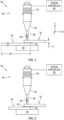
- the present disclosure is directed to a system 20 and method for joining components (e.g., a first component panel 22 and a second component panel 24 as will be detailed herein) that comprise one or more thermoplastic composite (TPC) materials.
- the system 20 includes an ultrasonic welding tool 26.
- the present disclosure system 20 may also include a system controller 28 and/or a stationary anvil 30 disposed on the side of the components opposite the ultrasonic welding tool 26.
- the present disclosure does not require a system controller or an anvil.
- thermoplastic materials that may be included within a TPC material (e.g., as a matrix material or the like) include polyaryletherketone (PAEK), polyetheretherketone (PEEK), polyetherketoneketone (PEKK), polyetherimide (PEI), perfluoroalkopxy (PFA), polytetrafluoroethylene (PTFE), polyphenylene sulfide (PPS), and polyamide (PA - "nylon”), and variations and/or combinations thereof.
- PAEK polyaryletherketone
- PEEK polyetheretherketone
- PEKK polyetherketoneketone
- PEI polyetherimide
- PFA perfluoroalkopxy
- PTFE polytetrafluoroethylene
- PPS polyphenylene sulfide
- PA - "nylon" polyamide
- each of the components 22, 24 to be joined may comprise the same TPC material(s) or may comprise different TPC materials; e.g., a first component comprising a first TPC material, a second component comprising a second TPC material that is different from the first TPC material, and so on.
- the present disclosure may be used to join components that comprise a homogenous TPC material, or components that include a plurality layers of different TPC materials, or the like.
- the present disclosure may be used to join TPC components with an interface layer 32 disposed between the TPC components.
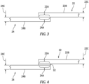
- the interface layer 32 may be a single (i.e., unitary) body that is disposed throughout a bond region (e.g., see FIG. 1 ), or it may be a plurality of independent segments (e.g., strips) disposed within the bond region (e.g., see FIG. 2 ).
- the interface layer 32 comprises at least one type of thermoplastic material.
- the interface layer 32 may have a homogenous configuration (e.g., the same thermoplastic material throughout), or it may include a fibrous material distributed within a thermoplastic material matrix (e.g., discontinuous fibers), or it may include a plurality of sublayers with different materials.
- a non-limiting example of an interface layer 32 with a plurality of sub-layers is one that includes a sub-layer comprising a mesh material, or a cloth material, or a screen material, or a layer of continuous fibers, or the like.
- Non-limiting examples of fiber material include ceramic, glass, metal, carbon, and the like.
- FIGS. 1 and 2 diagrammatically illustrate the first and second components configured as a first component panel 22 and a second component panel 24 to facilitate the description herein; e.g., panels having a thickness ("T"; Z-axis), a width ("W"; X-axis), and a length (perpendicular to the page; Y-axis), wherein the thickness is substantially less than width or length.
- the present disclosure is not limited to joining components having any particular configuration. However, the present disclosure provides great utility in joining components configured as panels; e.g., aircraft components such as fins, control surfaces, stabilizers, and the like.
- the surface portion of the first component panel 22 (FCP) aligned for bonding may be referred to herein as the FCP bonding surface 22A.
- the surface portion of the second component panel 24 (SCP) aligned for bonding may be referred to herein as the SCP bonding surface 24A.
- the first component panel 22 includes an FCP outer surface 22B opposite the FCP bonding surface 22A and a FCP thickness 22C that extends therebetween.
- the second component panel 24 includes an SCP outer surface 24B opposite the SCP bonding surface and a thickness 24C that extends therebetween.
- an interface layer 32 e.g., see FIG.
- the FCP bonding surface 22Aand the SCP bonding surface 24A are disposed in contact with one another prior to bonding.
- the interface layer 32 is disposed between the FCP bonding surface 22A and the SCP bonding surface 24A.
- FIGS. 5 and 5A illustrate a present disclosure ultrasonic welding tool 26 embodiment.
- FIG. 5A is an expanded view of a portion of the ultrasonic welding tool 26 embodiment shown in FIG. 5 .
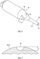
- FIG. 6 diagrammatically illustrates a portion of an alternative present disclosure ultrasonic welding tool 26 embodiment.
- the ultrasonic welding tool 26 embodiment shown in FIG. 5 includes a transducer 34, a step horn 36, and an ultrasonic tool 38 disposed along a longitudinal axis 40.
- the step horn 36 may have a tapered configuration (e.g., a conical or generally conical configuration), extending longitudinally between a first end 44 and a second end 46, the step horn 36 having a major diameter disposed at the first end 44, a minor diameter disposed at the second end 46, and a middle diameter between the first end 44 and the second end 46.
- the step horn 36 has an exterior surface 48 that extends longitudinally between the first end 44 and the second end 46 and around a circumference of the step horn 36.
- the ultrasonic tool 38 may be cylindrically shaped, extending longitudinally between a first end 50 and a distal second end 52 (also referred to as the tool tip 52).
- the ultrasonic tool 38 has an exterior surface 54 that extends longitudinally between the first end 50 and the tool tip 52 and around a circumference of the ultrasonic tool 38.
- a power supply (not shown) provides high frequency electrical signals to the transducer 34.
- the transducer 34 in turn converts high-frequency electricity into high-frequency (ultrasonic) vibrations.
- the step horn 36 focuses the ultrasound vibrations and delivers them to the ultrasonic tool 38 and the ultrasonic tool 38 in turn delivers the ultrasonic vibrations to the components to be joined.
- the ultrasonic welding tool 26 embodiments shown in FIGS. 5, 5A and 6 include a plurality of helical grooves 56.
- the helical grooves 56 may be disposed in the exterior surface 54 of the ultrasonic tool 38 portion of the ultrasonic welding tool 26 (e.g., see FIGS. 5 and 5A ), or in the exterior surface 48 of the step horn 36 portion of the ultrasonic welding tool 26 (e.g., see FIG. 6 ), or both.
- the present disclosure is not limited to any particular number of helical grooves 56 other than two or more. Our analysis indicates that a number of helical grooves 56 in the range of three to eight (3-8) helical grooves 56 works well for most ultrasonic welding tool 26 embodiments.
- the plurality of helical grooves 56 may be uniformly spaced relative to one another around the circumference of the respective portion of the ultrasonic welding tool 26; e.g., an embodiment having four (4) helical grooves 56 may have the grooves 56 circumferentially spaced ninety degrees (90°) apart from one another.
- the helical grooves 56 are disposed at an angle (" ⁇ ") in the range of about thirty to sixty degrees (30° - 60°) relative to the longitudinal axis of the ultrasonic welding tool 26; e.g., see FIG. 5A .
- the helical grooves 56 typically extending a depth distance ("D" - see FIG.
- the helical slot depth distance ("D") from the exterior surface 48 is about fifteen to twenty five (15-25%) of the radius of the step horn 36 at the longitudinal middle of the step horn 36.
- Our analysis indicates that a helical slot depth distance ("D") from the exterior surface 48, 54 at about twenty percent (20%) of the radius of the structure in which it is disposed works well.
- the ultrasonic tool 38 portion and the step horn 36 portion of the present disclosure ultrasonic welding tool 26 may be configured as a solid structure other than the aforesaid helical grooves 56.
- the FIGURES diagrammatically illustrate the helical grooves 56 as having a parti-circular cross-sectional geometry.
- the helical grooves 56 are not limited to having a parti-circular cross-sectional geometry; e.g., alternative cross-sectional geometries that may be used include elliptical geometries, oval geometries and other arcuate cross-sectional geometries.
- the longitudinal length ("L") of the helical grooves 56 (e.g., see FIG. 6 ) can be selected to suit the application at hand.
- the helical grooves 56 extend a distance "L” around the circumference of the ultrasonic tool 38 from about the intersection between the step horn 36 and the ultrasonic tool 38 to a separation distance ("SD") from the tool tip 52.
- SD separation distance
- a first end of each helical groove 56 is disposed in close proximity to the second end 46 of the step horn 36.
- the separation distance "SD" is substantially less than the length "L” of the grooves 56; e.g., the separation distance SD may be limited to a length "SD” sufficient to avoid undesirable stress concentrations at or in close proximity to the tool tip 52.
- FIGS. 5A the separation distance "SD" is substantially less than the length "L" of the grooves 56; e.g., the separation distance SD may be limited to a length "SD" sufficient to avoid undesirable stress concentrations at or in close proximity to the tool tip 52.
- the helical grooves 56 extend a distance "L" that is greater than fifty percent (50%) of the axial length of the ultrasonic tool (i.e., the axial length of the ultrasonic tool 38 between the first end 50 of the ultrasonic tool 38 and the tool tip 52).
- the embodiment shown in FIGS. 5 and 5A is understood to perform particularly well in a continuous welding seam process wherein the ultrasonic welding tool 26 is moved relative to thermoplastic components 22, 24 or vice versa.
- the helical grooves 56 extend around the circumference of the step horn 36 a distance "L" that may be at least about fifty percent (50%) or more of the distance between the first and second ends 44, 46 of the step horn 36.
- the helical grooves 56 extending in a helical direction around the step horn 36 or ultrasonic tool 38 desirably convert a higher percentage of a longitudinal excitation wave to a torsional vibration component than is possible with a straight line groove.
- system controller 28 is in communication with other components within the system 20, including the ultrasonic welding tool 26.
- the system controller 28 may be in communication with these components to control and/or receive signals therefrom to perform the functions described herein.
- the system controller 28 may include any type of computing device, computational circuit, processor(s), CPU, computer, or the like capable of executing a series of instructions that are stored in memory.
- the instructions may include an operating system, and/or executable software modules such as program files, system data, buffers, drivers, utilities, and the like.
- the executable instructions may apply to any functionality described herein to enable the system 20 to accomplish the same algorithmically and/or coordination of system components.
- the system controller 28 includes or is in communication with one or more memory devices.
- the present disclosure is not limited to any particular type of memory device, and the memory device may store instructions and/or data in a non-transitory manner.
- Examples of memory devices that may be used include read-only memory, random access memory, volatile memory, non-volatile memory, static memory, dynamic memory, flash memory, cache memory, and/or any device that stores digital information.
- the system controller 28 may include, or may be in communication with, an input device that enables a user to enter data and/or instructions, and may include, or be in communication with, an output device configured, for example to display information (e.g., a visual display device as indicated above or a printer), or to transfer data, etc. Communications between the system controller 28 and other system components may be via a hardwire connection or via a wireless connection.
- the linear ultrasonic vibration (parallel to the longitudinal axis) generates heat as a result of friction and viscoelastic response at the interface between components to be joined.
- the linear ultrasonic vibration produced by a conventional device includes torsional mode vibration at the tool tip, that torsional mode vibration does not appreciably contribute to the heat generation.
- the present disclosure ultrasonic welding tool 26 with helical grooves 56 produces a composite ultrasonic vibration that includes a longitudinal component throughout the ultrasonic tool 38 portion and a torsional component, the latter being large enough to produce appreciable torsional vibration at the tool tip 52; i.e., rotational movement of the tool tip 52.
- present disclosure ultrasonic welding tools 26 with helical grooves 56 may produce up to ten times (10x) the amount of torsional mode vibration at the tool tip 52 than is produced by a comparable ultrasonic welding tool without the aforesaid helical slots.
- the torsional mode vibration at the tool tip 52 is understood to improve surface heat generation and to mitigate undesirable bending modes.
- the torsional mode vibration produced by the present disclosure acts as a sliding motion, which is understood to provide a significant benefit when the present disclosure ultrasonic welding tool 26 is used to produce a continuous welding seam between thermoplastic components 22, 24.
- the torsional mode vibration provides a sliding motion which helps to smooth the welding area and facilitates movement between the ultrasonic tool 36 portion of the ultrasonic welding tool 26 and the thermoplastic components 22, 24 being joined along a continuous seam.
- any one of these structures may describe the operations as a sequential process, many of the operations can be performed in parallel or concurrently.
- the order of the operations may be rearranged.
- a process may correspond to a method, a function, a procedure, a subroutine, a subprogram, etc.
- the terms “comprise”, “comprising”, or any other variation thereof, are intended to cover a non-exclusive inclusion, such that a process, method, article, or apparatus that comprises a list of elements does not include only those elements but may include other elements not expressly listed or inherent to such process, method, article, or apparatus.
Landscapes
- Engineering & Computer Science (AREA)
- Mechanical Engineering (AREA)
- Textile Engineering (AREA)
- Lining Or Joining Of Plastics Or The Like (AREA)
- Pressure Welding/Diffusion-Bonding (AREA)
Applications Claiming Priority (1)
| Application Number | Priority Date | Filing Date | Title |
|---|---|---|---|
| US18/228,477 US12528136B2 (en) | 2023-07-31 | 2023-07-31 | Method and apparatus for ultrasonic welding thermoplastic components |
Publications (1)
| Publication Number | Publication Date |
|---|---|
| EP4501595A1 true EP4501595A1 (de) | 2025-02-05 |
Family
ID=91375057
Family Applications (1)
| Application Number | Title | Priority Date | Filing Date |
|---|---|---|---|
| EP24179357.9A Pending EP4501595A1 (de) | 2023-07-31 | 2024-05-31 | Verfahren und vorrichtung zum ultraschallschweissen von thermoplastischen komponenten |
Country Status (2)
| Country | Link |
|---|---|
| US (1) | US12528136B2 (de) |
| EP (1) | EP4501595A1 (de) |
Citations (9)
| Publication number | Priority date | Publication date | Assignee | Title |
|---|---|---|---|---|
| JP2013111508A (ja) * | 2011-11-25 | 2013-06-10 | Nihon Univ | 超音波複合振動装置 |
| CN108748366A (zh) * | 2018-05-31 | 2018-11-06 | 河南理工大学 | 模态叠加式纵-扭复合超声振动加工方法及装置 |
| CN108787407A (zh) * | 2018-05-31 | 2018-11-13 | 河南理工大学 | 单激励匹配式变螺旋纵-扭复合超声振动加工方法及装置 |
| US20190033264A1 (en) * | 2016-02-04 | 2019-01-31 | Instituto Superior Tecnico | Equipment For Fatigue Testing At Ultrasonic Frequencies In The Multiaxial Regime-Axial And Torsional Directions |
| EP3659717A1 (de) | 2018-11-27 | 2020-06-03 | MS Ultraschall Technologie GmbH | Sonotrode |
| EP3718647A1 (de) | 2019-04-01 | 2020-10-07 | Branson Ultraschall Niederlassung der Emerson Technologies GmbH & Co. oHG | Torsionshorn und ultraschallbearbeitungsverfahren unter verwendung des torsionshorns |
| EP3822018A1 (de) | 2019-11-15 | 2021-05-19 | Telsonic Holding AG | Ultraschallkomponente, vorrichtung zum bearbeiten von werkstücken und verfahren zum bearbeiten von werkstücken |
| WO2022194383A1 (de) * | 2021-03-19 | 2022-09-22 | Telsonic Holding Ag | Ultraschallbooster und vorrichtung zum bearbeiten von werkstücken |
| US20230158629A1 (en) * | 2021-11-19 | 2023-05-25 | Raytheon Technologies Corporation | Method for machining ceramic workpiece with composite vibration |
Family Cites Families (8)
| Publication number | Priority date | Publication date | Assignee | Title |
|---|---|---|---|---|
| DE4406818C1 (de) | 1994-03-02 | 1995-10-05 | Schunk Ultraschalltechnik Gmbh | Verfahren und Vorrichtung zum Verschweißen von zumindest Metallteilen |
| JP2002209906A (ja) * | 2001-01-23 | 2002-07-30 | Miwatec:Kk | 超音波ハンドピ−ス |
| JP2003190180A (ja) * | 2001-12-27 | 2003-07-08 | Miwatec:Kk | 複合振動超音波ハンドピ−ス |
| US7651490B2 (en) * | 2004-08-12 | 2010-01-26 | Alcon, Inc. | Ultrasonic handpiece |
| US7572242B2 (en) * | 2004-03-22 | 2009-08-11 | Alcon, Inc. | Method of operating an ultrasound handpiece |
| DE202005003067U1 (de) | 2005-02-25 | 2005-05-12 | Kln Ultraschall Gmbh | Sonotrode für die Ultraschall-Verschweißung von thermoplastischen Werkstücken |
| CN208246950U (zh) | 2018-05-31 | 2018-12-18 | 河南理工大学 | 模态叠加式纵-扭复合超声振动加工装置 |
| WO2020105434A1 (ja) * | 2018-11-20 | 2020-05-28 | 株式会社Link-Us | 超音波接合装置 |
-
2023
- 2023-07-31 US US18/228,477 patent/US12528136B2/en active Active
-
2024
- 2024-05-31 EP EP24179357.9A patent/EP4501595A1/de active Pending
Patent Citations (10)
| Publication number | Priority date | Publication date | Assignee | Title |
|---|---|---|---|---|
| JP2013111508A (ja) * | 2011-11-25 | 2013-06-10 | Nihon Univ | 超音波複合振動装置 |
| US20190033264A1 (en) * | 2016-02-04 | 2019-01-31 | Instituto Superior Tecnico | Equipment For Fatigue Testing At Ultrasonic Frequencies In The Multiaxial Regime-Axial And Torsional Directions |
| CN108748366A (zh) * | 2018-05-31 | 2018-11-06 | 河南理工大学 | 模态叠加式纵-扭复合超声振动加工方法及装置 |
| CN108787407A (zh) * | 2018-05-31 | 2018-11-13 | 河南理工大学 | 单激励匹配式变螺旋纵-扭复合超声振动加工方法及装置 |
| EP3659717A1 (de) | 2018-11-27 | 2020-06-03 | MS Ultraschall Technologie GmbH | Sonotrode |
| EP3718647A1 (de) | 2019-04-01 | 2020-10-07 | Branson Ultraschall Niederlassung der Emerson Technologies GmbH & Co. oHG | Torsionshorn und ultraschallbearbeitungsverfahren unter verwendung des torsionshorns |
| EP3822018A1 (de) | 2019-11-15 | 2021-05-19 | Telsonic Holding AG | Ultraschallkomponente, vorrichtung zum bearbeiten von werkstücken und verfahren zum bearbeiten von werkstücken |
| WO2022194383A1 (de) * | 2021-03-19 | 2022-09-22 | Telsonic Holding Ag | Ultraschallbooster und vorrichtung zum bearbeiten von werkstücken |
| US20240165735A1 (en) | 2021-03-19 | 2024-05-23 | Telsonic Holding Ag | Ultrasonic booster and device for processing workpieces |
| US20230158629A1 (en) * | 2021-11-19 | 2023-05-25 | Raytheon Technologies Corporation | Method for machining ceramic workpiece with composite vibration |
Also Published As
| Publication number | Publication date |
|---|---|
| US20250041962A1 (en) | 2025-02-06 |
| US12528136B2 (en) | 2026-01-20 |
Similar Documents
| Publication | Publication Date | Title |
|---|---|---|
| US10399274B2 (en) | Method for using transverse sonotrode in ultrasonic welding | |
| EP2544880B1 (de) | System zur verbesserung der sonotrodenleistung in anwendungen zur additivherstellung mittels ultraschall | |
| JP6317820B2 (ja) | コンバーターユニット | |
| US5976316A (en) | Non-nodal mounting system for acoustic horn | |
| EP3099468B1 (de) | Ultraschallsonotrode für transversal ausgerichteten wandler | |
| EP3964721A1 (de) | Verbindung von objekten | |
| US11311960B2 (en) | High-efficiency welding assembly for use in ultrasonic additive manufacturing | |
| KR20010075145A (ko) | 슬리브가 있는 회전형 음파 호온 | |
| EP4501595A1 (de) | Verfahren und vorrichtung zum ultraschallschweissen von thermoplastischen komponenten | |
| CN1486239A (zh) | 对称超声波旋转焊头 | |
| US10150178B2 (en) | Method and apparatus for vibration welding | |
| CN1291936A (zh) | 熔接聚合物织物的方法和装置 | |
| Belardi et al. | Structural analysis of transversally loaded quasi-isotropic rectilinear orthotropic composite circular plates with Galerkin method | |
| Mughal et al. | DESIGN AND PERFORMANCE EVALUATION OF A NOVEL ULTRASONIC WELDING SONOTRODE FOR LANGEVIN TRANSDUCER USING FINITE ELEMENT APPROACH. | |
| JP2018134858A (ja) | 熱可塑性樹脂複合材料の加工方法、結合方法及び加工装置並びに熱可塑性樹脂複合材料 | |
| WO2021262001A1 (en) | Rounded sonotrode | |
| WO2006074323A2 (en) | Ultrasonic welder with high-q tool | |
| Miller et al. | Assessment of Thermoplastic Composite Joining by Resistance, Induction, and Ultrasonic Welding | |
| EP4299292B1 (de) | Schwingungsschweissverfahren und -system | |
| Ferreira et al. | Geometry effect on the static strength of curved composite bonded joints | |
| Jairaja | Experimental and Numerical Studies to Strengthen the Adhesive Bonded Single Lap Joint | |
| KR101428974B1 (ko) | 복합 소재와 금속재의 접합 유닛 및 접합 방법 | |
| Seo et al. | Optimal Welding condition in Ultrasonic Welding of Ni steel sheet | |
| Nitoi et al. | ULTRASONIC WELDING BETWEEN ALUMINUM AND GLASS FIBRE | |
| Odobescu | The application of longitudinal wave propagation theory in case of impedance transformers utilized for ultrasonic welding |
Legal Events
| Date | Code | Title | Description |
|---|---|---|---|
| PUAI | Public reference made under article 153(3) epc to a published international application that has entered the european phase |
Free format text: ORIGINAL CODE: 0009012 |
|
| STAA | Information on the status of an ep patent application or granted ep patent |
Free format text: STATUS: THE APPLICATION HAS BEEN PUBLISHED |
|
| AK | Designated contracting states |
Kind code of ref document: A1 Designated state(s): AL AT BE BG CH CY CZ DE DK EE ES FI FR GB GR HR HU IE IS IT LI LT LU LV MC ME MK MT NL NO PL PT RO RS SE SI SK SM TR |
|
| TPAC | Observations filed by third parties |
Free format text: ORIGINAL CODE: EPIDOSNTIPA |
|
| STAA | Information on the status of an ep patent application or granted ep patent |
Free format text: STATUS: REQUEST FOR EXAMINATION WAS MADE |
|
| 17P | Request for examination filed |
Effective date: 20250805 |
|
| STAA | Information on the status of an ep patent application or granted ep patent |
Free format text: STATUS: EXAMINATION IS IN PROGRESS |
|
| 17Q | First examination report despatched |
Effective date: 20251127 |