EP4501607A1 - Verfahren zur herstellung eines faserverstärkten verbundartikels - Google Patents
Verfahren zur herstellung eines faserverstärkten verbundartikels Download PDFInfo
- Publication number
- EP4501607A1 EP4501607A1 EP23382810.2A EP23382810A EP4501607A1 EP 4501607 A1 EP4501607 A1 EP 4501607A1 EP 23382810 A EP23382810 A EP 23382810A EP 4501607 A1 EP4501607 A1 EP 4501607A1
- Authority
- EP
- European Patent Office
- Prior art keywords
- mould plate
- mould
- cavity
- preform
- fibre
- Prior art date
- Legal status (The legal status is an assumption and is not a legal conclusion. Google has not performed a legal analysis and makes no representation as to the accuracy of the status listed.)
- Withdrawn
Links
Images

Classifications
-
- B—PERFORMING OPERATIONS; TRANSPORTING
- B29—WORKING OF PLASTICS; WORKING OF SUBSTANCES IN A PLASTIC STATE IN GENERAL
- B29D—PRODUCING PARTICULAR ARTICLES FROM PLASTICS OR FROM SUBSTANCES IN A PLASTIC STATE
- B29D24/00—Producing articles with hollow walls
- B29D24/002—Producing articles with hollow walls formed with structures, e.g. cores placed between two plates or sheets, e.g. partially filled
- B29D24/004—Producing articles with hollow walls formed with structures, e.g. cores placed between two plates or sheets, e.g. partially filled the structure having vertical or oblique ribs
-
- B—PERFORMING OPERATIONS; TRANSPORTING
- B29—WORKING OF PLASTICS; WORKING OF SUBSTANCES IN A PLASTIC STATE IN GENERAL
- B29C—SHAPING OR JOINING OF PLASTICS; SHAPING OF MATERIAL IN A PLASTIC STATE, NOT OTHERWISE PROVIDED FOR; AFTER-TREATMENT OF THE SHAPED PRODUCTS, e.g. REPAIRING
- B29C70/00—Shaping composites, i.e. plastics material comprising reinforcements, fillers or preformed parts, e.g. inserts
- B29C70/04—Shaping composites, i.e. plastics material comprising reinforcements, fillers or preformed parts, e.g. inserts comprising reinforcements only, e.g. self-reinforcing plastics
- B29C70/28—Shaping operations therefor
- B29C70/40—Shaping or impregnating by compression not applied
- B29C70/42—Shaping or impregnating by compression not applied for producing articles of definite length, i.e. discrete articles
- B29C70/44—Shaping or impregnating by compression not applied for producing articles of definite length, i.e. discrete articles using isostatic pressure, e.g. pressure difference-moulding, vacuum bag-moulding, autoclave-moulding or expanding rubber-moulding
-
- B—PERFORMING OPERATIONS; TRANSPORTING
- B29—WORKING OF PLASTICS; WORKING OF SUBSTANCES IN A PLASTIC STATE IN GENERAL
- B29D—PRODUCING PARTICULAR ARTICLES FROM PLASTICS OR FROM SUBSTANCES IN A PLASTIC STATE
- B29D24/00—Producing articles with hollow walls
-
- B—PERFORMING OPERATIONS; TRANSPORTING
- B29—WORKING OF PLASTICS; WORKING OF SUBSTANCES IN A PLASTIC STATE IN GENERAL
- B29C—SHAPING OR JOINING OF PLASTICS; SHAPING OF MATERIAL IN A PLASTIC STATE, NOT OTHERWISE PROVIDED FOR; AFTER-TREATMENT OF THE SHAPED PRODUCTS, e.g. REPAIRING
- B29C43/00—Compression moulding, i.e. applying external pressure to flow the moulding material; Apparatus therefor
- B29C43/32—Component parts, details or accessories; Auxiliary operations
- B29C43/36—Moulds for making articles of definite length, i.e. discrete articles
- B29C43/3642—Bags, bleeder sheets or cauls for isostatic pressing
- B29C2043/3649—Inflatable bladders using gas or fluid and related details
-
- B—PERFORMING OPERATIONS; TRANSPORTING
- B29—WORKING OF PLASTICS; WORKING OF SUBSTANCES IN A PLASTIC STATE IN GENERAL
- B29L—INDEXING SCHEME ASSOCIATED WITH SUBCLASS B29C, RELATING TO PARTICULAR ARTICLES
- B29L2031/00—Other particular articles
- B29L2031/30—Vehicles, e.g. ships or aircraft, or body parts thereof
- B29L2031/3064—Trains
Definitions
- the present invention relates to a method for manufacturing a fibre-reinforced composite article having at least one cavity, a mould for manufacturing the article, a system for manufacturing the article and to the fibre-reinforced composite article obtainable by the method thereof.
- WO2020120896A1 discloses a curing mold for manufacturing a turbomachine part made of composite material from a preform produced by draping pre-impregnated materials, comprising: a first body and a second body designed to be attached to each other and jointly defining a fixed air gap for receiving the preform and itself comprising a molding part of complementary shape with the part to be manufactured and intended to receive a portion to be molded of the preform, and at least one additional part located in a peripheral space of the air gap and intended to receive an additional portion forming an edge of the preform; a heating element designed to heat the preform in the air gap to a first temperature; at least one inflatable bladder housed in the first or second body, facing an additional part of the air gap; a member for injecting a pressurized fluid inside the bladder(s), the or each of the bladders being in addition adapted to compress, in the inflated state, the additional portion of the preform, located in the additional
- WO2018196514A1 discloses a method for preparing a composite material gas intake passage and a composite material gas intake passage, wherein the preparation method comprises the following steps: a) laying at least one layer of a prepreg on a female mould to form a prepreg layer; b) placing a gasbag in the prepreg layer, and completing mould assembly; c) inflating the gasbag to a predetermined pressure, and pressing the prepreg layer between the outer surface of the gasbag and the inner surface of the female mould; d) subjecting the entire mould assembled in step c) to a curing treatment; and e) relieving the pressure in the gasbag and opening the mould to release the prepared composite material gas intake passage green body.
- KR101387394B1 relates to a method for manufacturing a composite hollow structure and a mold thereof, wherein the manufacturing method includes arranging a prepreg in a mold and arranging a tube inside the prepreg.
- KR102312637B1 relates to a tubular high-speed molding method that comprises a first step of laminating a carbon fiber prepreg on a cavity of a lower mold and engaging a tubular mold and the lower mold; a second step of injecting a heating medium oil heated to a preset temperature to the upper part of the tubular mold at a preset pressure; a third step of forming the carbon fiber prepreg by expanding a flexible membrane; a fourth step of discharging the heating medium oil inside the tubular mold; and a fifth step of cooling the lower mold.
- the railway sector is currently turning its attention to the replacement of components or parts, which to date were made of aluminum or other heavier materials, with fibre-reinforced composite parts whose advantage is reduced weight compared to equal or better mechanical properties.
- the heaviest and/or repetitive elements are in the spotlight and that is where the fairings come into play.
- the trains are covered by fairings and are heavy parts that are repeated in large numbers in all the train cars, so their replacement would present significant advantages.
- the main problem with current sandwich-type parts is that they have a high cost since they are manufactured with a highly manual manufacturing system and high cycle times (pre-preg autoclave) and the cost of the core or nucleus is high since this core has to meet various requirements, such as being fireproof, not absorbing resin, withstanding high temperatures and pressures during the fibre-reinforced composite curing process without (or minimal) deformations, being easy to machine and cut, etc., amounting to a whole series of requirements that make these materials very expensive and difficult to control during manufacturing processes. It is for these reasons that its use in mass manufacturing processes is not widespread.
- one aspect of the present invention relates to a method for manufacturing a fibre-reinforced composite article having at least one cavity, the method comprising the steps of: providing two laminates or preforms obtained by coating a fibre reinforcement with a resin, said at least two laminates or preforms having at least one joining region and at least one cavity defining region, placing the first laminate or preform in a lower mould plate of a mould as defined hereinbelow, placing the second laminate or preform in an upper mould plate of a mould as defined hereinbelow, placing a fluid impermeable element covering the at least one cavity defining region of the two laminates or preforms, closing the lower mould plate with the upper mould plate so that the second laminate or preform is placed over the first laminate or preform, so that at least one cavity is created between opposite cavity defining regions of the two laminates or preforms and so that the joining regions of the first and second laminates are in contact and overlapping one another, injecting a fluid to the at least one
- the step of curing the first and second preform may comprise the steps of: applying a pressure to the lower mould plate and/or to the upper mould plate; and heating the lower mould plate and/or the upper mould plate.
- the method herein further discloses that the first and second laminates or preforms may have two cavity defining regions, one peripheral joining region and one intermediate joining region between the two cavity defining regions and in connection with the peripheral joining region, so that when the lower mould plate is closed with the upper mould plate, two cavities are created between opposite cavity defining regions and the peripheral and intermediate joining regions of the first and second laminates or preforms are in contact and overlapping one another, so that curing the first and second laminates or preforms forms a fibre reinforced composite article having two cavities between a first and a second wall joined together in a peripheral joining region and in an intermediate joining region between both cavities.
- the method herein disclosed may further comprise the step of placing at least one reinforcing element on the first preform, said reinforcing element being shaped so as to be in contact with the second preform when the mould is closed.
- step of curing the first and second preform in the method herein disclosed may further comprise the step of curing the at least one reinforcing element so that it joins to the first and second preforms.
- the method herein disclosed may further comprise the step of cooling the fibre-reinforced composite article after curing and before opening the mould.
- the fluid injected in the at least one cavity may be compressed air.
- the method herein disclosed may further comprise the step of placing at least one injector and removing said at least one injector.
- the fluid impermeable element in the method disclosed herein may be composed of a polymer comprising a resin of polyester, vinyl-ester, epoxide and/or combinations thereof.
- the fluid impermeable element disclosed in the present method may preferably be a film or an expandable container.
- the expandable container covers the cavity so that the internal parts of the layers are in contact with the container, and this may be achieved by inflating air into an expandable container, as in a balloon, so that the container contacts the internal layers of the cavity, or just by covering the internal layers of the cavity with a film.
- a mould for manufacturing a fibre-reinforced composite article having at least one cavity following a method as disclosed herein comprising: a lower mould plate; an upper mould plate for closing the lower mould plate and for defining a moulding cavity together with the lower mould plate; and at least one fluid injection port for injecting a fluid to at least one cavity defined between a first laminate or preform placed in the lower mould plate and a second laminate or preform placed in the upper mould plate.
- the at least one fluid injection port may be comprised in the lower and/or upper mould plate.
- the mould as disclosed herein may have a substantially polygonal shape.
- the mould as disclosed herein may comprise at least one fluid injection port on at least two opposite faces thereof.
- the lower mould plate and/or the upper mould plate in the mould as disclosed herein may comprise a cooling circuit for the passage of a cooling fluid.
- Another aspect of the present invention relates to a system for manufacturing a fibre-reinforced composite article having at least one cavity following a method as disclosed herein, the system comprising: a mould as disclosed herein; a pressure applying unit for applying a pressure to the upper and/or lower mould plate of the mould; a heating unit for heating the mould; and a fluid pressurizing unit fluidly connected to the at least one fluid injection port of the mould.
- the heating unit in the system herein disclosed may be in thermal contact with the upper mould plate and/or with the lower mould plate.
- the system as defined herein may further comprise at least one pump fluidly connected to the cooling circuit of the mould.
- the pressure applying unit in the system herein may be a press.
- the mould in the system as disclosed herein may have a substantially quadrangular shape and may comprise at least two diagonally opposed pressure applying units.
- Each pressure unit in the system disclosed herein may comprise a tubular guide attached to the upper or lower mould plate and passing through the opposite mould plate; and a compressed spring abutting against a spring retention element and to said opposite mould plate.
- the spring retention element in the system herein disclosed may be threaded to the tubular guide.
- the mould in the system as disclosed herein may be detachable from the rest of components of the system.
- Another aspect of the present invention relates to a fibre-reinforced composite article having at least one cavity obtainable by the method for manufacturing a composite article as disclosed herein.
- the at least one cavity may be defined between a first and a second wall joined together at least in a peripheral joining region wherein the first and second walls may be substantially parallel one another.
- the at least one cavity may comprise at least one reinforcing element interconnecting the first and second walls.
- the fibre-reinforced composite article herein disclosed may comprise two cavities defined between the first and second walls joined together in the peripheral joining region and in an intermediate joining region between both cavities and in connection with the peripheral joining region.
- references to geometric position such as parallel, perpendicular, tangent, etc. allow deviations up to ⁇ 5° from the theoretical position defined by this nomenclature.
- the laminates according to the present invention might be obtained by coating a fibre reinforcement with a resin by pre-impregnating the dry fibre with an adequate resin, cutting the laminates or preforms with the required dimensions, introducing the laminates in preform moulds to perform a pre-forming of the laminates to obtain a preform.
- FIG. 1 The process of obtaining a fibre reinforced article 1 is schematically drawn in FIG. 1 , wherein a fibre reinforcement made of fibres is treated with a resin, preferably an epoxy resin, to form a prepreg.
- a resin preferably an epoxy resin
- the prepreg is cut and layered and then is preformed in a mould 2.
- the preforms are transferred into the mould 2 disclosed in the present invention, the mould is closed and a fluid is injected into the cavity 10.
- the preforms in the mould are then cured, the fluid is released and the mould is opened and the article obtained 1 is demoulded.
- the article 1 can then be used in the application deemed appropriate.
- the fibre-reinforced composite article 1 as disclosed herein has at least one cavity 10 and this cavity 10 is obtained without the need of a core that needs to be removed after curing. Moreover, the two laminates or preforms 11, 12 are joined in their joining regions 13 without the need of an adhesive -the walls are joined together when curing the first and second laminate or preform 11, 12.
- the fluid impermeable element prevents the fluid injected in the cavity 10 to be diffused across/through the laminates or preforms 11,12.
- the fluid impermeable element covering the cavity defining region 14 is preferably placed on the laminates or preforms 11, 12.
- the fluid impermeable element is preferably deposited onto the laminates or preforms 11, 12 as a layer, covering the whole surface except the joining region 13 of the laminates or preforms 11, 12 that will be faced when manufacturing the article 1.
- the fibre according to this disclosure may be preferably selected from the group of carbon fibre, glass fibre or natural fibre.
- the fibre is reinforced and impregnated by a resin, so that a fibre reinforced polymer laminate or preform 11, 12 is obtained.
- the article 1 obtained by the method as disclosed herein has the following structure, depicted schematically in FIG. 2A .
- the article has an upper skin or layer and a lower skin or layer both of them made of fibre-reinforced composite separated from each other by an air chamber, the air chamber defining a cavity 10.
- both skins are in contact by a joining region 13, obtaining a closed component.
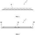
- Another embodiment of the article according to the disclosure may have a central or intermediate joining region 131 so that two cavities 10 are defined, as shown in FIG. 4 .
- more than one joining regions 13 might be present in the article, so more than two cavities 10 may be defined.
- two centrally placed parallel intermediate joining regions 131 placed might be present in the article 1 and therefore three cavities 10 might be defined.
- two centrally placed perpendicular intermediate joining regions 131 might be present in the article 1 and therefore four cavities 10 might be defined.
- the central or intermediate joining region 131 does not go across the whole article 1, and therefore it does not form two separate cavities 10.
- these components or articles may have a small inlet and outlet holes for a gas or fluid, as shown in e.g. FIG. 2B and FIG. 4 , which once the part is cured, may be covered with structural resin to obtain completely hermetic parts.
- the fibre-reinforced composite article 1 as disclosed herein may contain a reinforcing element 15 interconnecting the first and second walls of the article, as shown in FIG. 3 .
- the reinforcing element 15 may be corrugated in a preferred embodiment.
- the components are cured preferably in a single curing cycle and no adhesive at all binding the different parts of the components are present, as required by the railway regulations.
- the article 1 as disclosed herein and obtained by the method according to the present disclosure has the advantages of other state-of-the-art articles in that the thickness and inertia are increased, while the weight, and the costs associated with the manufacture of such articles are decreased. In particular, the cycle time is significantly reduced.
- the article 1 as defined herein has the functionality of guaranteeing the tightness. Moreover, in the railway sector, the article allows access to the equipment installed under the passengers compartment of the train cabin, facilitating its installation, assembly and maintenance, houses all closing and opening systems, ensures sufficient structure to support the different elements/equipment that will be attached to it, favours the soundproofing of the cabin, protects the bottom of the train from possible impacts and complies with the technical requirements according to railway regulations.
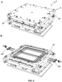
- FIG. 5 The system 3 as disclosed herein is depicted in FIG. 5 .
- the system 3 comprises the mould 2 configured to obtain the article 1 as disclosed herein.
- FIG. 5B shows a system comprising the lower part of the mould 21 that produces an article having two cavities because a central joining region is defined therein.
- FIG. 5B also discloses two fluid injection ports 24 in the lower mould plate 21 for injecting a fluid into the two cavities 10 defined between the first laminate or preform 11 placed in the lower mould plate 21 and a second laminate or preform 12 placed in the upper mould plate 22.
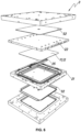
- FIG. 6 An embodiment showing different parts of the system 3 as disclosed herein are also depicted in FIG. 6 , in an exploded view.
- the system depicted shows a mould 2 configured to produce an article 1 having two cavities 10 separated by a central joining region 131 and two fluid injection ports 24 to inject the fluid into each of the two cavities defined.
- the central joining region can also be obtained by a conveniently placed insert 25 that, when the two laminates or preforms 11, 12 are closed in the mould, the lower laminate or preform 11 achieves the desired geometry producing an article 1 having two cavities 10.
- the system 3 as disclosed may be designed so that the mould 2 is detachable, so that the forming of the laminates or preforms 11, 12 is performed independently in the lower and upper mould plate 21, 22 and the set of non-cured article 1 plus the mould plates 21, 22 is then introduced in the system 3 for the curing step by the heating unit 32. While the curing step is taking place, another mould 2 comprising the mould plates 21, 22 can be available and forming a second set of laminates or preforms 11, 12. This configuration allows decreasing the production cycle time of articles, because the system 3 does not need to cool down before and after the forming of articles 1 but may be constantly heated.
Landscapes
- Engineering & Computer Science (AREA)
- Mechanical Engineering (AREA)
- Chemical & Material Sciences (AREA)
- Composite Materials (AREA)
- Casting Or Compression Moulding Of Plastics Or The Like (AREA)
Priority Applications (3)
| Application Number | Priority Date | Filing Date | Title |
|---|---|---|---|
| EP23382810.2A EP4501607A1 (de) | 2023-08-03 | 2023-08-03 | Verfahren zur herstellung eines faserverstärkten verbundartikels |
| PCT/EP2024/071570 WO2025027030A1 (en) | 2023-08-03 | 2024-07-30 | Method for manufacturing a fibre-reinforced composite article |
| CN202480050861.2A CN121843810A (zh) | 2023-08-03 | 2024-07-30 | 制造纤维增强复合材料制品的方法 |
Applications Claiming Priority (1)
| Application Number | Priority Date | Filing Date | Title |
|---|---|---|---|
| EP23382810.2A EP4501607A1 (de) | 2023-08-03 | 2023-08-03 | Verfahren zur herstellung eines faserverstärkten verbundartikels |
Publications (1)
| Publication Number | Publication Date |
|---|---|
| EP4501607A1 true EP4501607A1 (de) | 2025-02-05 |
Family
ID=87845876
Family Applications (1)
| Application Number | Title | Priority Date | Filing Date |
|---|---|---|---|
| EP23382810.2A Withdrawn EP4501607A1 (de) | 2023-08-03 | 2023-08-03 | Verfahren zur herstellung eines faserverstärkten verbundartikels |
Country Status (3)
| Country | Link |
|---|---|
| EP (1) | EP4501607A1 (de) |
| CN (1) | CN121843810A (de) |
| WO (1) | WO2025027030A1 (de) |
Citations (7)
| Publication number | Priority date | Publication date | Assignee | Title |
|---|---|---|---|---|
| US20100196637A1 (en) * | 2007-04-02 | 2010-08-05 | Mt Aerospace Ag | Method for producing fibre-reinforced hollow bodies and products formed using said method |
| KR101387394B1 (ko) | 2011-12-30 | 2014-04-22 | 연세대학교 산학협력단 | 복합재 중공구조물 제조방법 및 그 금형 |
| KR20150127470A (ko) * | 2014-05-07 | 2015-11-17 | 주식회사 오코 | 가스배출이 용이한 섬유강화 복합재 성형용 몰드 |
| WO2018196514A1 (zh) | 2017-04-28 | 2018-11-01 | 深圳光启高等理工研究院 | 复合材料进气道制备方法及复合材料进气道 |
| WO2020120896A1 (fr) | 2018-12-14 | 2020-06-18 | Safran | Moule de cuisson pour fabriquer une piece de turbomachine en materiau composite a partir d'une preforme et procede de fabrication d'une piece au moyen d'un tel moule |
| WO2021172597A1 (ja) * | 2020-10-09 | 2021-09-02 | 株式会社The MOT Company | 繊維強化樹脂材の成形品製造装置および成形品の製造方法 |
| KR102312637B1 (ko) | 2021-06-24 | 2021-10-14 | 주식회사 하이인텍 | 튜브형 고속 성형방법 |
Family Cites Families (1)
| Publication number | Priority date | Publication date | Assignee | Title |
|---|---|---|---|---|
| DE102013109460B4 (de) * | 2013-08-30 | 2016-11-03 | Cotesa Gmbh | Behälter aus Faserverbundwerkstoffen mit innenliegender Funktionsschicht und Verfahren zu dessen Herstellung |
-
2023
- 2023-08-03 EP EP23382810.2A patent/EP4501607A1/de not_active Withdrawn
-
2024
- 2024-07-30 WO PCT/EP2024/071570 patent/WO2025027030A1/en active Pending
- 2024-07-30 CN CN202480050861.2A patent/CN121843810A/zh active Pending
Patent Citations (7)
| Publication number | Priority date | Publication date | Assignee | Title |
|---|---|---|---|---|
| US20100196637A1 (en) * | 2007-04-02 | 2010-08-05 | Mt Aerospace Ag | Method for producing fibre-reinforced hollow bodies and products formed using said method |
| KR101387394B1 (ko) | 2011-12-30 | 2014-04-22 | 연세대학교 산학협력단 | 복합재 중공구조물 제조방법 및 그 금형 |
| KR20150127470A (ko) * | 2014-05-07 | 2015-11-17 | 주식회사 오코 | 가스배출이 용이한 섬유강화 복합재 성형용 몰드 |
| WO2018196514A1 (zh) | 2017-04-28 | 2018-11-01 | 深圳光启高等理工研究院 | 复合材料进气道制备方法及复合材料进气道 |
| WO2020120896A1 (fr) | 2018-12-14 | 2020-06-18 | Safran | Moule de cuisson pour fabriquer une piece de turbomachine en materiau composite a partir d'une preforme et procede de fabrication d'une piece au moyen d'un tel moule |
| WO2021172597A1 (ja) * | 2020-10-09 | 2021-09-02 | 株式会社The MOT Company | 繊維強化樹脂材の成形品製造装置および成形品の製造方法 |
| KR102312637B1 (ko) | 2021-06-24 | 2021-10-14 | 주식회사 하이인텍 | 튜브형 고속 성형방법 |
Also Published As
| Publication number | Publication date |
|---|---|
| WO2025027030A1 (en) | 2025-02-06 |
| CN121843810A (zh) | 2026-04-10 |
Similar Documents
| Publication | Publication Date | Title |
|---|---|---|
| US8834782B2 (en) | Composite structures and methods of making same | |
| US5112663A (en) | Method of manufacturing composite structures | |
| EP1972428B1 (de) | Zwischenplatte zur herstellung von verbundkunststoffteilen. | |
| CN107225773B (zh) | 用于组装加强的复合结构的方法 | |
| US20090039566A1 (en) | Composite structures and methods of making same | |
| CA2245088C (en) | Method for forming inner mold line tooling without a part model | |
| US20130127092A1 (en) | Moulded multilayer plastics component with continuously reinforced fibre plies and process for producing this component | |
| JP2014504218A5 (de) | ||
| EP3075523B1 (de) | Frp-formvorrichtung und verfahren zum formen einer frp-struktur | |
| US20130089742A1 (en) | Reinforced internal composite structures | |
| CN1008157B (zh) | 纤维增强空心结构及其制作方法 | |
| CN104136202A (zh) | 设有向外开口型内腔的复合材料制本体的制造方法和设备 | |
| WO2008109029A2 (en) | Composite article debulking process | |
| CN101068668B (zh) | 成型前体、纤维增强树脂成型体的制造方法及纤维增强树脂成型体 | |
| EP1595688B1 (de) | Geformter Schichtstoff und Verfahren zu dessen Herstellung | |
| CN101653990A (zh) | 微型无人机机身与垂尾一体化固化成型方法及其固化模具 | |
| CN102046348A (zh) | 用于制造包括由复合材料制成的中空主体的部件的方法 | |
| EP1687131B1 (de) | Entlüftungsfolie für verbundwerkstoffaushärtung und anordnungsverfahren dafür | |
| CN108506393B (zh) | 一种仿生复合材料碟簧零件及其制备方法 | |
| US5863365A (en) | Method of manufacturing composite articles | |
| US7527757B2 (en) | Method of producing polyimide matrix composite parts | |
| WO2018001642A1 (en) | Moulding composite panels | |
| CA2795861A1 (en) | Method and device for producing a composite moulded part from fibre-reinforced plastic | |
| CN86105175A (zh) | 吸收能量的泡沫-织物层压件 | |
| EP4501607A1 (de) | Verfahren zur herstellung eines faserverstärkten verbundartikels |
Legal Events
| Date | Code | Title | Description |
|---|---|---|---|
| PUAI | Public reference made under article 153(3) epc to a published international application that has entered the european phase |
Free format text: ORIGINAL CODE: 0009012 |
|
| STAA | Information on the status of an ep patent application or granted ep patent |
Free format text: STATUS: THE APPLICATION HAS BEEN PUBLISHED |
|
| AK | Designated contracting states |
Kind code of ref document: A1 Designated state(s): AL AT BE BG CH CY CZ DE DK EE ES FI FR GB GR HR HU IE IS IT LI LT LU LV MC ME MK MT NL NO PL PT RO RS SE SI SK SM TR |
|
| STAA | Information on the status of an ep patent application or granted ep patent |
Free format text: STATUS: THE APPLICATION IS DEEMED TO BE WITHDRAWN |
|
| 18D | Application deemed to be withdrawn |
Effective date: 20250806 |