EP4501645A1 - Tête d'évacuation de liquide et dispositif d'impression - Google Patents
Tête d'évacuation de liquide et dispositif d'impression Download PDFInfo
- Publication number
- EP4501645A1 EP4501645A1 EP23780221.0A EP23780221A EP4501645A1 EP 4501645 A1 EP4501645 A1 EP 4501645A1 EP 23780221 A EP23780221 A EP 23780221A EP 4501645 A1 EP4501645 A1 EP 4501645A1
- Authority
- EP
- European Patent Office
- Prior art keywords
- flow channel
- communication flow
- pressurizing chamber
- discharge
- manifold
- Prior art date
- Legal status (The legal status is an assumption and is not a legal conclusion. Google has not performed a legal analysis and makes no representation as to the accuracy of the status listed.)
- Pending
Links
Images


Classifications
-
- B—PERFORMING OPERATIONS; TRANSPORTING
- B41—PRINTING; LINING MACHINES; TYPEWRITERS; STAMPS
- B41J—TYPEWRITERS; SELECTIVE PRINTING MECHANISMS, i.e. MECHANISMS PRINTING OTHERWISE THAN FROM A FORME; CORRECTION OF TYPOGRAPHICAL ERRORS
- B41J2/00—Typewriters or selective printing mechanisms characterised by the printing or marking process for which they are designed
- B41J2/005—Typewriters or selective printing mechanisms characterised by the printing or marking process for which they are designed characterised by bringing liquid or particles selectively into contact with a printing material
- B41J2/01—Ink jet
- B41J2/135—Nozzles
- B41J2/14—Structure thereof only for on-demand ink jet heads
- B41J2/14201—Structure of print heads with piezoelectric elements
- B41J2/14209—Structure of print heads with piezoelectric elements of finger type, chamber walls consisting integrally of piezoelectric material
- B41J2002/14225—Finger type piezoelectric element on only one side of the chamber
-
- B—PERFORMING OPERATIONS; TRANSPORTING
- B41—PRINTING; LINING MACHINES; TYPEWRITERS; STAMPS
- B41J—TYPEWRITERS; SELECTIVE PRINTING MECHANISMS, i.e. MECHANISMS PRINTING OTHERWISE THAN FROM A FORME; CORRECTION OF TYPOGRAPHICAL ERRORS
- B41J2/00—Typewriters or selective printing mechanisms characterised by the printing or marking process for which they are designed
- B41J2/005—Typewriters or selective printing mechanisms characterised by the printing or marking process for which they are designed characterised by bringing liquid or particles selectively into contact with a printing material
- B41J2/01—Ink jet
- B41J2/135—Nozzles
- B41J2/14—Structure thereof only for on-demand ink jet heads
- B41J2/14201—Structure of print heads with piezoelectric elements
- B41J2002/14306—Flow passage between manifold and chamber
-
- B—PERFORMING OPERATIONS; TRANSPORTING
- B41—PRINTING; LINING MACHINES; TYPEWRITERS; STAMPS
- B41J—TYPEWRITERS; SELECTIVE PRINTING MECHANISMS, i.e. MECHANISMS PRINTING OTHERWISE THAN FROM A FORME; CORRECTION OF TYPOGRAPHICAL ERRORS
- B41J2/00—Typewriters or selective printing mechanisms characterised by the printing or marking process for which they are designed
- B41J2/005—Typewriters or selective printing mechanisms characterised by the printing or marking process for which they are designed characterised by bringing liquid or particles selectively into contact with a printing material
- B41J2/01—Ink jet
- B41J2/135—Nozzles
- B41J2/14—Structure thereof only for on-demand ink jet heads
- B41J2002/14362—Assembling elements of heads
-
- B—PERFORMING OPERATIONS; TRANSPORTING
- B41—PRINTING; LINING MACHINES; TYPEWRITERS; STAMPS
- B41J—TYPEWRITERS; SELECTIVE PRINTING MECHANISMS, i.e. MECHANISMS PRINTING OTHERWISE THAN FROM A FORME; CORRECTION OF TYPOGRAPHICAL ERRORS
- B41J2/00—Typewriters or selective printing mechanisms characterised by the printing or marking process for which they are designed
- B41J2/005—Typewriters or selective printing mechanisms characterised by the printing or marking process for which they are designed characterised by bringing liquid or particles selectively into contact with a printing material
- B41J2/01—Ink jet
- B41J2/135—Nozzles
- B41J2/14—Structure thereof only for on-demand ink jet heads
- B41J2002/14459—Matrix arrangement of the pressure chambers
-
- B—PERFORMING OPERATIONS; TRANSPORTING
- B41—PRINTING; LINING MACHINES; TYPEWRITERS; STAMPS
- B41J—TYPEWRITERS; SELECTIVE PRINTING MECHANISMS, i.e. MECHANISMS PRINTING OTHERWISE THAN FROM A FORME; CORRECTION OF TYPOGRAPHICAL ERRORS
- B41J2/00—Typewriters or selective printing mechanisms characterised by the printing or marking process for which they are designed
- B41J2/005—Typewriters or selective printing mechanisms characterised by the printing or marking process for which they are designed characterised by bringing liquid or particles selectively into contact with a printing material
- B41J2/01—Ink jet
- B41J2/135—Nozzles
- B41J2/14—Structure thereof only for on-demand ink jet heads
- B41J2002/14491—Electrical connection
-
- B—PERFORMING OPERATIONS; TRANSPORTING
- B41—PRINTING; LINING MACHINES; TYPEWRITERS; STAMPS
- B41J—TYPEWRITERS; SELECTIVE PRINTING MECHANISMS, i.e. MECHANISMS PRINTING OTHERWISE THAN FROM A FORME; CORRECTION OF TYPOGRAPHICAL ERRORS
- B41J2202/00—Embodiments of or processes related to ink-jet or thermal heads
- B41J2202/01—Embodiments of or processes related to ink-jet heads
- B41J2202/11—Embodiments of or processes related to ink-jet heads characterised by specific geometrical characteristics
Definitions
- the disclosed embodiments relate to a liquid discharge head and a recording apparatus.
- Inkjet printers and inkjet plotters utilizing an inkjet recording method are known as printing apparatus.
- a liquid discharge head for discharging a liquid is mounted in such a printing apparatus using an inkjet method.
- Such a liquid discharge head includes a plurality of discharge holes, a plurality of pressurizing chambers respectively connected to the plurality of discharge holes, and a manifold commonly connected to the plurality of pressurizing chambers.
- the plurality of pressurizing chambers include a pressurizing chamber relatively far from the manifold and a pressurizing chamber relatively close to the manifold (for example, see Patent Document 1).
- Patent Document 1 JP 2005-35291 A
- a liquid discharge head includes a flow channel member including a first surface and a second surface located opposite to the first surface, and a pressurizer located on the first surface.
- the flow channel member includes a first discharge hole and a second discharge hole located in the second surface, a first individual flow channel connected to the first discharge hole, a first pressurizing chamber located upstream of the first discharge hole in the first individual flow channel, a second individual flow channel connected to the second discharge hole, a second pressurizing chamber located upstream of the second discharge hole in the second individual flow channel, and a manifold commonly connected to an upstream side of the first individual flow channel and an upstream side of the second individual flow channel.
- the first individual flow channel includes a first communication flow channel connecting the first pressurizing chamber and the first discharge hole.
- the second individual flow channel includes a second communication flow channel connecting the second pressurizing chamber and the second discharge hole.
- the second pressurizing chamber is located closer to the manifold than the first pressurizing chamber in a plan view. A width of at least part of the second communication flow channel is different from a width of the first communication flow channel.
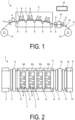
- FIG. 1 is a side view schematically illustrating the printer 1 according to an embodiment.
- FIG. 2 is a plan view schematically illustrating the printer 1 according to an embodiment.
- the printer 1 includes a paper feed roller 2, guide rollers 3, an applicator 4, a head case 5, a plurality of transport rollers 6, a plurality of frames 7, a plurality of liquid discharge heads 8, transport rollers 9, a dryer 10, transport rollers 11, a sensor 12, and a collection roller 13.
- the printer 1 further includes a controller 14 configured to control each part of the printer 1.
- the controller 14 controls the operation of the paper feed roller 2, the guide rollers 3, the applicator 4, the head case 5, the plurality of transport rollers 6, the plurality of frames 7, the plurality of liquid discharge heads 8, the transport rollers 9, the dryer 10, the transport rollers 11, the sensor 12, and the collection roller 13.
- the printer 1 By landing droplets on a printing sheet P, the printer 1 records images and characters on the printing sheet P.
- the printing sheet P is wound around the paper feed roller 2 in a drawable state before use.
- the printer 1 conveys the printing sheet P from the paper feed roller 2 to the inside of the head case 5 via the guide rollers 3 and the applicator 4.
- the applicator 4 uniformly applies a coating agent over the printing sheet P. This can perform surface treatment on the printing sheet P, improving the printing quality of the printer 1.
- the head case 5 houses the plurality of transport rollers 6, the plurality of frames 7, and the plurality of liquid discharge heads 8.
- the inside of the head case 5 is formed with a space separated from the outside except for a part connected to the outside such as parts where the printing sheet P enters and exits.
- the controller 14 controls at least one of controllable factors of the internal space of the head case 5, such as temperature, humidity, and air pressure.
- the transport rollers 6 convey the printing sheet P near the liquid discharge heads 8 inside the head case 5.
- the frames 7 are rectangular flat plates and are positioned above and close to the printing sheet P to be conveyed by the transport rollers 6. As illustrated in FIG. 2 , the plurality of frames 7 (e.g., four) are provided inside the head case 5 such that the longitudinal direction thereof is orthogonal to the conveying direction of the printing sheet P. The plurality of frames 7 are disposed at predetermined intervals along the conveying direction of the printing sheet P.
- the conveying direction of the printing sheet P may be referred to as "sub scanning direction”, and the direction orthogonal to the sub scanning direction and parallel to the printing sheet P may be referred to as "main scanning direction”.
- a liquid for example, ink
- a liquid tank (not illustrated).
- Each liquid discharge head 8 discharges the liquid supplied from the liquid tank.
- the controller 14 controls the liquid discharge heads 8 based on data of an image, characters, or the like to discharge the liquid toward the printing sheet P.
- the distance between each liquid discharge head 8 and the printing sheet P is, for example, approximately 0.5 to 20 mm.
- Each of the liquid discharge heads 8 is fixed to the frame 7.
- each of the liquid discharge heads 8 is fixed to the frame 7 at both end portions in the longitudinal direction.
- Each of the liquid discharge heads 8 is fixed to the frame 7 such that its longitudinal direction is parallel to the main scanning direction.
- the printer 1 according to the embodiment is a so-called line printer in which the liquid discharge heads 8 are fixed inside the printer 1.
- the printer 1 according to the embodiment is not limited to a line printer and may also be a so-called serial printer.
- a serial printer is a printer employing a method of alternately performing an operation of recording while moving the liquid discharge heads 8 in a manner to reciprocate or the like in a direction intersecting (e.g., substantially orthogonal to) the conveying direction of the printing sheet P and an operation of conveying the printing sheet P.
- FIG. 2 illustrates an example in which two liquid discharge heads 8 are arranged in front of the sub scanning direction and three liquid discharge heads 8 are arranged behind the sub scanning direction, and the liquid discharge heads 8 are arranged in the sub scanning direction such that the centers of the liquid discharge heads 8 do not overlap with each other.
- the plurality of liquid discharge heads 8 provided in one frame 7 form a head group 8A.
- Four head groups 8A are positioned along the sub scanning direction.
- the liquid discharge heads 8 belonging to the same head group 8A are supplied with ink of the same color.
- the printer 1 can perform printing with four colors of ink using the four head groups 8A.
- the colors of the ink discharged from the respective head groups 8A are, for example, magenta (M), yellow (Y), cyan (C), and black (K).
- the controller 14 can print a color image on the printing sheet P by controlling the respective head groups 8A to discharge the plurality of colors of ink onto the printing sheet P.
- a surface treatment may be performed on the printing sheet P, by discharging a coating agent from the liquid discharge head 8 onto the printing sheet P.
- the number of the liquid discharge heads 8 included in one head group 8A and the number of the head groups 8A mounted in the printer 1 can be changed as appropriate in accordance with printing targets and printing conditions. For example, when the color to be printed on the printing sheet P is a single color and the range of the printing can be covered by a single liquid discharge head 8, only a single liquid discharge head 8 may be provided in the printer 1.
- the printing sheet P printed inside the head case 5 is conveyed to the outside of the head case 5 by the transport rollers 9 and passes through the inside of the dryer 10.
- the dryer 10 dries the printing sheet P printed.
- the printing sheet P dried by the dryer 10 is transported by the transport rollers 11 and then collected by the collection roller 13.
- the printer 1 by drying the printing sheet P with the dryer 10, it makes it possible to suppress bonding, or rubbing of an undried liquid, between the printing sheets P overlapped with each other and rolled at the collection roller 13.
- the sensor 12 includes a position sensor, a speed sensor, a temperature sensor, or the like. Based on information from the sensor 12, the controller 14 can determine the state of each part of the printer 1 and control each part of the printer 1.
- the printing sheet P is used as the printing target (i.e., the recording medium), but the printing target in the printer 1 is not limited to the printing sheet P, and a rolled cloth or the like may be used as the printing target.
- the printer 1 described above may have a configuration in which the printing sheet P is put on a conveyor belt and conveyed. By using the conveyor belt, the printer 1 can perform printing on a sheet of paper, a cut cloth, wood, a tile, or the like as a printing target.
- the printer 1 described above may discharge a liquid containing electrically conductive particles from the liquid discharge heads 8, printing a wiring pattern or the like of an electronic device.
- the printer 1 described above may discharge liquid containing a predetermined amount of liquid chemical agent or liquid containing the chemical agent from the liquid discharge heads 8 onto a reaction vessel or the like to produce chemicals.
- the printer 1 described above may also include a cleaner for cleaning the liquid discharge heads 8.
- the cleaner cleans the liquid discharge heads 8 by, for example, a wiping process or a capping process.
- the wiping process is, for example, a process of removing liquid attached to a second surface 24b (see FIG. 3 ) of a flow channel member 24 (see FIG. 3 ), which is an example of a surface of a portion onto which the liquid is discharged, by rubbing the second surface 24b with a flexible wiper.
- the capping process is a process for removing clogging on a first discharge hole 46 (see FIG. 5 ) and a second discharge hole 56 (see FIG. 5 ) by covering, with a cap, the portion where the liquid is discharged, and repeating the discharge of liquid.
- a cap is provided in a manner to cover the second surface 24b of the flow channel member 24 which is an example of the portion from which the liquid is discharged (this process is referred to as capping).
- This forms a substantially sealed space between the second surface 24b and the cap.
- the discharge of liquid is then repeated in such a sealed space.
- liquid with a viscosity higher than that in a normal state, foreign matter, or the like clogging the first discharge hole 46 and the second discharge hole 56 can be removed.
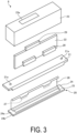
- FIG. 3 is an exploded perspective view illustrating an overall configuration of the liquid discharge head 8 according to an embodiment.
- the liquid discharge head 8 includes a head main body 20, a reservoir 21, an electrical board 22, and a head cover 23.
- the head main body 20 includes the flow channel member 24, a piezoelectric actuator substrate 25, a signal transmitter 26, and a drive IC 27.
- the flow channel member 24 of the head main body 20 has a substantially flat plate shape and includes a first surface 24a, which is one main surface, and the second surface 24b located opposite to the first surface 24a.
- the first surface 24a has an opening 40a (see FIG. 4 ), and liquid is supplied into the flow channel member 24 from the reservoir 21 through the opening 40a.
- a plurality of first discharge holes 46 (see FIG. 4 ) and a plurality of second discharge holes 56 (see FIG. 4 ) through which liquid is discharged onto the printing sheet P are located in the second surface 24b. Furthermore, a flow channel through which liquid flows from the first surface 24a to the second surface 24b is formed inside the flow channel member 24. Details of the flow channel member 24 will be described later.
- the piezoelectric actuator substrate 25 is located on the first surface 24a of the flow channel member 24.
- the piezoelectric actuator substrate 25 includes a plurality of displacement elements 38 (see FIG. 5 ).
- the displacement element 38 is an example of a pressurizer.
- the piezoelectric actuator substrate 25 will be described in detail later.
- Each signal transmitter 26 is electrically connected to the piezoelectric actuator substrate 25.
- Each signal transmitter 26 includes a plurality of the drive integrated circuits (ICs) 27. Note that, in FIG. 3 , one of the signal transmitters 26 is omitted for ease of understanding.
- the signal transmitter 26 supplies a signal to each displacement element 38 of the piezoelectric actuator substrate 25.
- the signal transmitter 26 is formed of, for example, a flexible printed circuit (FPC) or the like.
- the drive IC 27 is provided in the signal transmitter 26.
- the drive IC 27 controls driving of each displacement element 38 in the piezoelectric actuator substrate 25.
- the head main body 20 has a discharge surface from which the liquid is discharged and an opposite surface located on a side opposite to the discharge surface.
- the discharge surface is described as the second surface 24b of the flow channel member 24 and the opposite surface is described as the first surface 24a of the flow channel member 24.
- the reservoir 21 is located on the opposite surface side of the head main body 20 and is in contact with the first surface 24a excluding the piezoelectric actuator substrate 25.
- the reservoir 21 includes an opening 21a at each of both end portions thereof in the main scanning direction.
- the reservoir 21 has a flow channel therein, and is supplied with liquid from the outside through an opening 21a.
- the reservoir 21 has a function of supplying the liquid to the flow channel member 24 and a function of storing the liquid to be supplied.
- the electrical board 22 is provided in a standing manner on a surface on the side of the reservoir 21 opposite to the head main body 20.
- a plurality of connectors 28 are located on an end portion of the electrical board 22 on the reservoir 21 side.
- An end portion of the signal transmitter 26 is housed in each connector 28.
- Connectors 29 for power supply are located on an end portion of the electrical board 22 on the side opposite to the reservoir 21.
- the electrical board 22 distributes current, supplied from the outside via the connector 29, to the connectors 28 and supplies the current to the signal transmitter 26.
- the head cover 23 is located on the opposite surface side of the head main body 20 and covers the signal transmitter 26 and the electrical board 22. Thus, the liquid discharge heads 8 can seal the signal transmitter 26 and the electrical board 22.
- the head cover 23 includes an opening 23a.
- the connector 29 of the electrical board 22 is inserted to be exposed to the outside, through the opening 23a.
- the drive IC 27 is in contact with an interior side surface of the head cover 23.
- the drive IC 27 is pressed against the interior side surface of the head cover 23, for example.
- heat generated by the drive IC 27 can be dissipated (radiated) through a contact portion on the side surface of the head cover 23.
- liquid discharge head 8 may further include a member other than the member illustrated in FIG. 3 .
- FIG. 4 is an enlarged plan view of the head main body 20 according to an embodiment
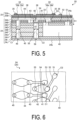
- FIG. 5 is a schematic cross-sectional view of the head main body 20 according to an embodiment
- FIG. 6 is an enlarged view of a region surrounded by a dash-dotted line in FIG. 4 .
- the head main body 20 includes the flow channel member 24 and the piezoelectric actuator substrate 25.
- the flow channel member 24 includes a supply manifold 40, a plurality of first pressurizing chambers 44, a plurality of second pressurizing chambers 54, the plurality of first discharge holes 46, and the plurality of second discharge holes 56.
- the supply manifold 40 is one example of a manifold.
- the plurality of first pressurizing chambers 44 and the plurality of second pressurizing chambers 54 are connected to the supply manifold 40.
- the plurality of first discharge holes 46 are connected to the plurality of first pressurizing chambers 44, respectively.
- the plurality of second discharge holes 56 are connected to the plurality of second pressurizing chambers 54, respectively.
- the first pressurizing chambers 44 and the second pressurizing chambers 54 open to the first surface 24a (see FIG. 5 ) of the flow channel member 24. Furthermore, the first surface 24a of the flow channel member 24 has the opening 40a that is connected to the supply manifold 40. Liquid is supplied from the reservoir 21 (see FIG. 2 ) to the inside of the flow channel member 24 through the opening 40a.
- the head main body 20 includes four supply manifolds 40 located inside the flow channel member 24.
- the supply manifold 40 has an elongated shape extending along the longitudinal direction of the flow channel member 24.
- the opening 40a is located in the first surface 24a of the flow channel member 24 at either end of the supply manifold 40.
- the plurality of first pressurizing chambers 44 and the plurality of second pressurizing chambers 54 are formed in the flow channel member 24 in a two-dimensionally spreading manner.
- the first pressurizing chambers 44 and the second pressurizing chambers 54 are hollow regions having a substantially diamond-shaped planar shape with rounded corners.
- the first pressurizing chambers 44 and the second pressurizing chambers 54 open to the first surface 24a of the flow channel member 24, and are closed when the piezoelectric actuator substrate 25 is joined to the first surface 24a.
- the first pressurizing chambers 44 form a first pressurizing chamber row arranged in the longitudinal direction of the flow channel member 24 (supply manifold 40), and the second pressurizing chambers 54 form a second pressurizing chamber row arranged in the longitudinal direction of the flow channel member 24 (supply manifold 40).
- the first pressurizing chambers 44 belonging to the first pressurizing chamber row and the second pressurizing chambers 54 belonging to the second pressurizing chamber row adjacent to the first pressurizing chamber row are alternately disposed.
- One pressurizing chamber group includes two rows of first pressurizing chamber rows and two rows of second pressurizing chamber rows connected to one supply manifold 40.
- the flow channel member 24 includes four pressurizing chamber groups.
- first pressurizing chambers 44 and the second pressurizing chambers 54 is the same among the pressurizing chamber groups, with the pressurizing chamber groups arranged while being slightly shifted from each other in the longitudinal direction.
- the first discharge holes 46 and the second discharge holes 56 are disposed at positions outside regions, of the flow channel member 24, facing the supply manifold 40. Thus, none of the first discharge holes 46 and the second discharge holes 56 overlap the supply manifold 40 in a perspective plane of the flow channel member 24 as viewed from the first surface 24a side.
- first discharge holes 46 and the second discharge holes 56 are disposed to be within a region in which the piezoelectric actuator substrate 25 is mounted.
- One group of the first discharge holes 46 and the second discharge holes 56 occupies a region of approximately the same size and shape as the piezoelectric actuator substrate 25.
- Droplets are discharged through the first discharge holes 46 and the second discharge holes 56 by displacing the displacement elements 38 (see FIG. 5 ) of the corresponding piezoelectric actuator substrate 25.
- the supply manifold 40 and the first discharge hole 46 are connected to each other via a first connection flow channel 41, a first aperture 42, a first supply flow channel 43, the first pressurizing chamber 44, and a first communication flow channel 45.
- the flow channel member 24 includes a first individual flow channel C1 including the first connection flow channel 41, the first aperture 42, the first supply flow channel 43, the first pressurizing chamber 44, and the first communication flow channel 45.
- the first connection flow channel 41 is located near the supply manifold 40 and the first communication flow channel 45 is located near the first discharge hole 46, in a flow direction of the liquid.
- first connection flow channel 41 extends in the first direction D1
- first aperture 42 extends in a direction perpendicular to the first direction D1
- first supply flow channel 43 extends in the first direction D1.
- first pressurizing chamber 44 extends in a direction perpendicular to the first direction D1
- first communication flow channel 45 extends in the first direction D1.
- the supply manifold 40 and the second discharge hole 56 are connected to each other via a second connection flow channel 51, a second aperture 52, a second supply flow channel 53, the second pressurizing chamber 54, and a second communication flow channel 55.
- the flow channel member 24 includes a second individual flow channel C2 including the second connection flow channel 51, the second aperture 52, the second supply flow channel 53, the second pressurizing chamber 54, and the second communication flow channel 55.
- the second connection flow channel 51 is located near the supply manifold 40 and the second communication flow channel 55 is located near the second discharge hole 56, in the flow direction of the liquid.
- connection flow channel 51 extends in the first direction D1
- second aperture 52 extends in a direction perpendicular to the first direction D1
- second supply flow channel 53 extends in the first direction D1.
- second pressurizing chamber 54 extends in a direction perpendicular to the first direction D1
- the second communication flow channel 55 extends in the first direction D1.
- the first individual flow channel C1 includes the first aperture 42 provided upstream of the first pressurizing chamber 44 and having a width narrower than other portions. With the width narrower than the other portions of the first individual flow channel C1, the first aperture 42 has a high flow channel resistance.
- the pressure generated in the first pressurizing chamber 44 can be suppressed from escaping to the supply manifold 40, instead of being directed to the first discharge holes 46. Therefore, according to the embodiment, the liquid can be efficiently discharged from the first discharge holes 46.
- the second individual flow channel C2 includes the second aperture 52 provided upstream of the second pressurizing chamber 54 and having a width narrower than other portions. With the width narrower than the other portions of the second individual flow channel C2, the second aperture 52 has a high flow channel resistance.
- the pressure generated in the second pressurizing chamber 54 can be suppressed from escaping to the supply manifold 40, instead of being directed to the second discharge holes 56. Therefore, according to the embodiment, the liquid can be efficiently discharged from the second discharge holes 56.
- the flow channel member 24 has a layered structure in which a plurality of plates are stacked. These plates include a cavity plate 24A, a base plate 24B, aperture plates 24C and 24D, a supply plate 24E, manifold plates 24F, 24G, and 24H, a cover plate 24I, and a nozzle plate 24J layered in this order from the first surface 24a of the flow channel member 24.
- FIG. 5 illustrates an example of the layered structure of the plates according to an embodiment, and there is no need to be particularly limited to the example illustrated in FIG. 5 .
- manifold plates 24F, 24G, and 24H may be formed by stacking three or more plates.
- the cover plate 24I may be formed by stacking a plurality of plates.
- a large number of holes are formed in the plates constituting the flow channel member 24, and the supply manifold 40, the first individual flow channel C 1, and the second individual flow channel C2 are formed inside the flow channel member 24, with the large number of holes connected to each other.
- the holes can be formed with increased accuracy.
- the first individual flow channel C1 includes the first communication flow channel 45 provided downstream of the first pressurizing chamber 44 and connecting the first pressurizing chamber 44 and the first discharge hole 46.
- the second individual flow channel C2 includes the second communication flow channel 55 provided downstream of the second pressurizing chamber 54 and connecting the second pressurizing chamber 54 and the second discharge hole 56.
- the second pressurizing chamber 54 is located closer to the supply manifold 40 than the first pressurizing chamber 44 in a plan view. That is, in the embodiment, in a plan view, the first pressurizing chamber 44 is relatively far from the supply manifold 40, and the second pressurizing chamber 54 is relatively close to the supply manifold 40. In the example of FIG. 6 , in a plan view, the first pressurizing chamber 44 is located away from the supply manifold 40 and does not overlap the supply manifold 40, but the second pressurizing chamber 54 has a portion overlapping the supply manifold 40.
- the width of the second communication flow channel 55 is different from the width of the first communication flow channel 45.
- the width of the second communication flow channel 55 is larger than the width of the first communication flow channel 45.
- the second pressurizing chamber 54 relatively close to the supply manifold 40 has lower rigidity than the first pressurizing chamber 44 relatively far from the supply manifold 40, and is likely to be displaced by pressurization from the displacement element 38.
- the first pressurizing chamber 44 and the second pressurizing chamber 54 there may be a variation in a discharge speed of liquid between the first discharge hole 46 and the second discharge hole 56.
- FIG. 7 is a view for illustrating a variation in amount of displacement between the first pressurizing chamber 44 and the second pressurizing chamber 54.
- FIG. 7 illustrates amounts of displacement of the first pressurizing chambers 44 belonging to the first pressurizing chamber rows and amounts of displacement of the second pressurizing chambers 54 belonging to the second pressurizing chamber rows.
- Row numbers illustrated in FIG. 7 are numbers indicating positions of the first pressurizing chamber row and the second pressurizing chamber row in a width direction of the flow channel member 24, and for example, numbers 1 to 16 are assigned as row numbers sequentially from the left side to eight rows of first pressurizing chamber rows and eight rows of second pressurizing chamber rows illustrated in FIG. 4 .
- the row numbers 1, 4, 5, 8, 9, 12, 13, and 16 correspond to the first pressurizing chamber rows
- the row numbers 2, 3, 6, 7, 10, 11, 14, and 15 correspond to the second pressurizing chamber rows.
- Column numbers illustrated in FIG. 7 are numbers indicating positions of the first pressurizing chambers 44 belonging to the first pressurizing chamber rows and the second pressurizing chambers 54 belonging to the second pressurizing chamber rows in the longitudinal direction of the flow channel member 24.
- the second pressurizing chamber 54 relatively close to the supply manifold 40 has a larger amount of displacement than the first pressurizing chamber 44 relatively far from the supply manifold 40.
- the discharge speed of liquid in the second discharge hole 56 connected to the second pressurizing chamber 54 is higher than that in the first discharge hole 46 connected to the first pressurizing chamber 44.
- the uniformity of the discharge speed of liquid between the first discharge hole 46 and the second discharge hole 56 is impaired.
- the discharge speed of liquid is made uniform between the first discharge hole 46 and the second discharge hole 56.
- FIG. 8 is a view illustrating an example of a relationship between the width of the second communication flow channel 55 and the discharge speed of the liquid discharged from the second discharge hole 56.
- the present inventors changed the width (flow channel width) of the second communication flow channel 55 to supply liquid to the inside of the flow channel member 24 and examined the discharge speed of the liquid discharged from the second discharge hole 56 by simulation.
- FIG. 8 illustrates a result of such a simulation.
- the discharge speed of the liquid discharged from the second discharge hole 56 reached the maximum value when the width of the second communication flow channel 55 was about 200 ⁇ m, and decreased from the maximum value when the width of the second communication flow channel 55 was smaller or larger than about 200 ⁇ m. It is considered that when the width of the second communication flow channel 55 is small, the flow channel resistance of the second communication flow channel 55 becomes high, and the pressure wave generated in the second pressurizing chamber 54 is not efficiently propagated to the second discharge hole 56, leading to a decrease in the discharge speed of the liquid.
- the width of the first communication flow channel 45 and the width of the second communication flow channel 55 are generally set so that the discharge speed of the liquid discharged from the discharge holes (the first discharge hole 46 and the second discharge hole 56) becomes a maximum value.
- the width of the first communication flow channel 45 and the width of the second communication flow channel 55 are set in the vicinity of 200 ⁇ m, which is a common setting value at which the discharge speed of the liquid becomes the maximum value.
- the discharge speed of the liquid discharged from the second discharge hole 56 is reduced so as to approach the discharge speed of the liquid discharged from the first discharge hole 46. Therefore, according to the embodiment, the uniformity of the discharge speed of liquid between the first discharge hole 46 and the second discharge hole 56 can be improved.
- the width of the second communication flow channel 55 is larger than the width of the first communication flow channel 45 in the embodiment, the width of the second communication flow channel 55 may be smaller than the width of the first communication flow channel 45. In short, it is sufficient that the width of the second communication flow channel 55 is different from the width of the first communication flow channel 45. In addition, the entire width of the second communication flow channel 55 is not necessarily required to be different from the width of the first communication flow channel 45. For example, a width of part of the second communication flow channel 55 may be different from the width of the first communication flow channel 45, and a width of another part of the second communication flow channel 55 may be the same as the width of the first communication flow channel 45. In short, it is sufficient that a width of at least part of the second communication flow channel 55 is different from the width of the first communication flow channel 45.
- the width of the second communication flow channel 55 may be larger than the width of the first communication flow channel 45 by 0.5% to 2.5%.
- the width of the second communication flow channel 55 is preferably larger than the width of the first communication flow channel 45 by about 1 to 5 ⁇ m. Accordingly, it is possible to suppress an excessive decrease in the discharge speed of the liquid discharged from the second discharge hole 56. Therefore, according to the embodiment, the uniformity of the discharge speed of liquid between the first discharge hole 46 and the second discharge hole 56 can be further improved.
- a diameter r2 of the hole for forming the second communication flow channel 55 is preferably larger than a diameter r1 of the hole for forming the first communication flow channel 45.
- FIG. 9 is a view illustrating specific examples of diameters of holes in the manifold plate 24H.
- FIG. 9 illustrates the diameter r1 of the hole for forming the first communication flow channel 45 and the diameter r2 of the hole for forming the second communication flow channel 55.
- the row numbers illustrated in FIG. 9 are numbers indicating positions of the holes for forming the first communication flow channels 45 and the holes for forming the second communication flow channels 55 in the width direction of the flow channel member 24.
- the same numbers as the row numbers of the corresponding first pressurizing chamber rows and second pressurizing chamber rows are assigned to the holes as row numbers.
- the row numbers 1, 4, 5, 8, 9, 12, 13, and 16 correspond to the holes for forming the first communication flow channel 45
- the row numbers 2, 3, 6, 7, 10, 11, 14, and 15 correspond to the holes for forming the second communication flow channel 55.
- the diameter r2 of the hole for forming the second communication flow channel 55 is larger than the diameter r1 of the hole for forming the first communication flow channel 45.
- the diameter r2 of the hole for forming the second communication flow channel 55 is larger than the diameter r1 of the hole for forming the first communication flow channel 45.
- the diameter r2 of the hole for forming the second communication flow channel 55 is larger than the diameter r1 of the hole for forming the first communication flow channel 45. Accordingly, the first communication flow channel 45 and the second communication flow channel 55 can be easily formed in the flow channel member 24 by aligning and stacking the manifold plates 24F, 24G, and 24H so that the respective holes communicate with each other.
- a thickness of each of the manifold plates 24F, 24G, and 24H may be larger than thicknesses of the other plates included in the plurality of plates constituting the flow channel member 24.
- the respective thicknesses of the manifold plates 24F, 24G, and 24H are larger than those of the other plates, such as the cavity plate 24A. Since the respective thicknesses of the manifold plates 24F, 24G, and 24H are larger than those of the other plates, a volume of the second communication flow channels 55 in the manifold plates 24F, 24G, and 24H can be made larger than a volume of the second communication flow channels 55 in the other plates.
- the pressure wave generated in the second pressurizing chamber 54 is absorbed and efficiently attenuated by the liquid in the second communication flow channels 55 in the manifold plates 24F, 24G, and 24H, so that an adjustment range of the discharge speed of the liquid discharged from the second discharge holes can be widened. Therefore, according to the embodiment, the uniformity of the discharge speed of liquid between the first discharge hole 46 and the second discharge hole 56 can be further improved.
- the diameter r2 of the hole for forming the second communication flow channel 55 is preferably larger than the diameter r1 of the hole for forming the first communication flow channel 45.
- the diameter r2 of the hole for forming the second communication flow channel 55 is larger than the diameter r1 of the hole for forming the first communication flow channel 45.
- the pressure wave generated in the second pressurizing chamber 54 is absorbed and efficiently attenuated by the liquid in the second communication flow channels 55 in the manifold plates 24F, 24G, and 24H and other plates, so that the adjustment range of the discharge speed of the liquid discharged from the second discharge holes 56 can be widened. Therefore, according to the embodiment, the uniformity of the discharge speed of liquid between the first discharge hole 46 and the second discharge hole 56 can be further improved.
- the piezoelectric actuator substrate 25 includes piezoelectric ceramic layers 25A and 25B, a common electrode 33, an individual electrode 34, a connection electrode 35, a dummy electrode 36, and a surface electrode 37 (see FIG. 4 ).
- the piezoelectric actuator substrate 25 includes the piezoelectric ceramic layer 25B, the common electrode 33, the piezoelectric ceramic layer 25A, and the individual electrode 34 stacked in this order.
- Each of the piezoelectric ceramic layers 25A and 25B extends across the plurality of first pressurizing chambers 44 and second pressurizing chambers 54.
- the piezoelectric ceramic layers 25A and 25B each have a thickness of about 20 ⁇ m.
- the piezoelectric ceramic layers 25A and 25B are made of a lead zirconate titanate (PZT)-based ceramic material having ferroelectricity.
- the common electrode 33 is formed over substantially the entire surface in a surface direction in a region between the piezoelectric ceramic layer 25A and the piezoelectric ceramic layer 25B. Thus, the common electrode 33 overlaps all of the first pressurizing chambers 44 and the second pressurizing chambers 54 in the region facing the piezoelectric actuator substrate 25.
- the thickness of the common electrode 33 is approximately 2 ⁇ m.
- the common electrode 33 is made of a metal material such as an Ag-Pd-based material.
- the individual electrode 34 includes a main body electrode 34a and an extraction electrode 34b.
- the main body electrode 34a is located in a region, on the piezoelectric ceramic layer 25A, facing the first pressurizing chambers 44 and the second pressurizing chambers 54.
- the main body electrode 34a is one size smaller than each first pressurizing chamber 44 and each second pressurizing chamber 54, and has a shape substantially similar to that of the first pressurizing chamber 44 and the second pressurizing chamber 54.
- the extraction electrode 34b is extracted from the main body electrode 34a to be outside the region facing the first pressurizing chambers 44 and the second pressurizing chambers 54.
- the individual electrode 34 is made of, for example, a metal material such as an Au-based material.
- connection electrode 35 is located on the extraction electrode 34b, and is formed to have a convex shape with a thickness of approximately 15 ⁇ m.
- the connection electrode 35 is electrically connected to an electrode provided to the signal transmitter 26 (see FIG. 3 ).
- the connection electrode 35 is made of, for example, silver-palladium, including glass frit.
- the dummy electrode 36 is located on the piezoelectric ceramic layer 25A and is located so as not to overlap various electrodes such as the individual electrode 34.
- the dummy electrode 36 connects the piezoelectric actuator substrate 25 and the signal transmitter 26 to each other, and increases the connection strength.
- the dummy electrode 36 uniformizes the distribution of the contact positions between the piezoelectric actuator substrate 25 and the signal transmitter 26, and stabilizes the electrical connection.
- the dummy electrode 36 is preferably made of a material equivalent to that of the connection electrode 35, and is preferably formed in a process equivalent to that of the connection electrode 35.
- the surface electrode 37 illustrated in FIG. 4 is formed on the piezoelectric ceramic layer 25A and at a position not interfering with the individual electrode 34.
- the surface electrode 37 is connected to the common electrode 33 through a via hole formed in the piezoelectric ceramic layer 25A.
- the surface electrode 37 is grounded and maintained at the ground electric potential.
- the surface electrode 37 is preferably made of a material equivalent to that of the individual electrode 34, and is preferably formed in a process equivalent to that of the individual electrode 34.
- a plurality of the individual electrodes 34 are individually electrically connected to the controller 14 (see FIG. 1 ) via the signal transmitter 26 and wiring, in order to individually control the potentials of each individual electrode 34. Then, when the individual electrode 34 and the common electrode 33 are set to different potentials and an electric field is applied in a polarization direction of the piezoelectric ceramic layer 25A, a part applied with the electric field in the piezoelectric ceramic layer 25A operates as an active part that is distorted by the piezoelectric effect.
- portions of the individual electrode 34, the piezoelectric ceramic layers 25A and 25B, and the common electrode 33 facing the first pressurizing chambers 44 and the second pressurizing chambers 54 function as the displacement elements 38.
- the individual electrodes 34 are set to a higher potential (hereinafter, also referred to as high potential) than the common electrode 33 in advance. Then, with the controller 14, each time a discharge request is made, the individual electrodes 34 are set to the same potential as the common electrode 33 (hereinafter referred to as low potential), and then are again set to the high potential at a predetermined timing.
- the piezoelectric ceramic layers 25A and 25B return to their original shape, and the volume of the first pressurizing chambers 44 and second pressurizing chambers 54 increases over that in the initial state, that is, the state with the high potential.
- the piezoelectric ceramic layers 25A and 25B deform so as to protrude toward the first pressurizing chamber 44 and the second pressurizing chamber 54 at the timing when the individual electrodes 34 are again set to the high potential.
- first pressurizing chamber 44 and the second pressurizing chamber 54 have a positive pressure as a result of the decreasing volume of the first pressurizing chamber 44 and the second pressurizing chamber 54.
- the pressure of the liquid inside the first pressurizing chamber 44 and the second pressurizing chamber 54 rises, and droplets are discharged from the first discharge holes 46 and the second discharge holes 56.
- the controller 14 supplies a drive signal including pulses based on the high potential to the individual electrodes 34 in order to discharge the droplets from the first discharge holes 46 and the second discharge holes 56.
- the pulse width need only be an acoustic length (AL), corresponding to a length of time required for pressure waves to propagate from the first connection flow channel 41 to the first discharge hole 46 (or from the second connection flow channel 51 to the second discharge hole 56).
- the gradient is expressed based on the number of droplets continuously discharged from the first discharge holes 46 and the second discharge holes 56, that is, the amount (volume) of droplets adjusted based on the number of times the droplets are discharged.
- the droplets are discharged by a number of times corresponding to the designated gradient to be expressed, through the first discharge holes 46 and the second discharge holes 56 corresponding to the designated dot region.
- an interval between the pulses that are supplied to discharge the droplets may be set to the AL. Due to this, a period of a residual pressure wave of pressure generated in discharging the droplets discharged earlier matches a period of a pressure wave of pressure to be generated in discharging droplets to be discharged later.
- the residual pressure wave and the pressure wave are superimposed, whereby the droplets can be discharged with a higher pressure. Note that in this case, the speed of the droplets to be discharged later increases, and the landing points of the plurality of droplets become closer.
- FIG. 10 is a schematic cross-sectional view of the head main body 20 according to another embodiment 1.
- At least one manifold plate of the manifold plates 24F, 24G, and 24H and the other manifold plates have different diameters of holes for forming the second communication flow channel 55.
- a diameter r21 of the hole for forming the second communication flow channel 55 in the manifold plates 24F and 24G is larger than a diameter r22 of the hole for forming the second communication flow channel 55 in the manifold plate 24H. Accordingly, since the volume of the second communication flow channel 55 in the manifold plates 24F, 24G, and 24H can be finely adjusted, an adjustment range of the discharge speed of the liquid discharged from the second discharge hole 56 can be widened. Therefore, according to another embodiment 1, the uniformity of the discharge speed of liquid between the first discharge hole 46 and the second discharge hole 56 can be further improved.
- central axes of the holes (holes for forming the second communication flow channels 55) of the manifold plates 24F, 24G, and 24H coincide with each other. Accordingly, even in a case where the diameters of the holes (holes for forming the second communication flow channels 55) of the manifold plates 24F, 24G, and 24H are different from each other, the liquid can be caused to flow along the central axes of the holes in the second communication flow channels 55. Therefore, according to another embodiment 1, it is possible to suppress disturbance of the flow of the liquid in the second communication flow channels 55.
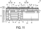
- FIG. 11 is a schematic cross-sectional view of the head main body 20 according to another embodiment 2.
- the manifold plates 24F, 24G, and 24H are different from each other in the diameter of the hole for forming the second communication flow channel 55. Accordingly, since the volume of the second communication flow channel 55 in the manifold plates 24F, 24G, and 24H can be finely adjusted, the adjustment range of the discharge speed of the liquid discharged from the second discharge hole 56 can be widened. Therefore, according to another embodiment 2, the uniformity of the discharge speed of liquid between the first discharge hole 46 and the second discharge hole 56 can be further improved.
- the diameters of the holes (holes for forming the second communication flow channels 55) of the manifold plates 24F, 24G, and 24H decrease as a position of the hole (hole for forming the second communication flow channel 55) in the first direction D1 approaches the second surface 24b. That is, the diameter r22 of the hole of the manifold plate 24G is smaller than the diameter r21 of the hole of the manifold plate 24F, and the diameter r23 of the hole of the manifold plate 24H is smaller than the diameter r22 of the hole of the manifold plate 24G.
- the volume of the second communication flow channel 55 in the manifold plates 24F, 24G, and 24H can be gradually decreased toward the downstream side of the liquid, the flow velocity of the liquid in the second communication flow channel 55 can be increased toward the second discharge hole 56. Therefore, according to another embodiment 2, the discharge of air or foreign matter from the second discharge holes 56 can be promoted.
- FIG. 12 is an enlarged plan view of a head main body 20 according to another embodiment 3.
- the position of the first pressurizing chamber 44 is different from that in the embodiment. Specifically, in a plan view, the first pressurizing chamber 44 is located closer to the supply manifold 40 as a whole than in the embodiment, and has a portion overlapping the supply manifold 40.
- an area of the portion of the first pressurizing chamber 44 overlapping the supply manifold 40 is smaller than an area of the portion of the second pressurizing chamber 54 overlapping the supply manifold 40 in a plan view.
- the first pressurizing chamber 44 and the second pressurizing chamber 54 can be disposed in the flow channel member 24 with high space efficiency.
- the flow channel member 24 can be downsized, whereby the head main body 20 can be downsized.
- the present disclosure is not limited to the embodiment described above, and various changes can be made without departing from the spirit of the present disclosure.
- the flow channel member 24 includes the plurality of layered plates
- the flow channel member 24 is not limited to the case of including the plurality of stacked plates.
- the flow channel member 24 may be configured with the supply manifold 40, the first individual flow channel C1, the second individual flow channel C2, and the like formed by etching.
- a liquid discharge head (for example, the liquid discharge head 8) according to an embodiment includes a flow channel member (for example, the flow channel member 24) including a first surface (for example, the first surface 24a) and a second surface (for example, the second surface 24b) located opposite to the first surface, and a pressurizer (for example, the displacement element 38) located on the first surface.
- a flow channel member for example, the flow channel member 24
- a second surface for example, the second surface 24b located opposite to the first surface
- a pressurizer for example, the displacement element 38
- the flow channel member includes a first discharge hole (for example, the first discharge hole 46) and a second discharge hole (for example, the second discharge hole 56) located in the second surface, a first individual flow channel (for example, the first individual flow channel C1) connected to the first discharge hole, a first pressurizing chamber (for example, the first pressurizing chamber 44) located upstream of the first discharge hole in the first individual flow channel, a second individual flow channel (for example, the second individual flow channel C2) connected to the second discharge hole, a second pressurizing chamber (for example, the second pressurizing chamber 54) located upstream of the second discharge hole in the second individual flow channel, and a manifold (for example, the supply manifold 40) commonly connected to an upstream side of the first individual flow channel and an upstream side of the second individual flow channel.
- a first individual flow channel for example, the first individual flow channel C1
- a first pressurizing chamber for example, the first pressurizing chamber 44
- second individual flow channel for example, the second individual flow channel C2
- the first individual flow channel includes a first communication flow channel (for example, the first communication flow channel 45) connecting the first pressurizing chamber and the first discharge hole.
- the second individual flow channel includes a second communication flow channel (for example, the second communication flow channel 55) connecting the second pressurizing chamber and the second discharge hole.
- the second pressurizing chamber is located closer to the manifold than the first pressurizing chamber in a plan view. A width of at least part of the second communication flow channel is different from a width of the first communication flow channel. Therefore, according to the liquid discharge head of the embodiment, the uniformity of the discharge speed of liquid can be improved.
- a width of at least part of the second communication flow channel may be larger than a width of the first communication flow channel.
- the width of at least part of the second communication flow channel may be larger than the width of the first communication flow channel by 0.5% to 2.5%.
- the flow channel member may have a layered structure in which a plurality of plates are stacked.
- the plurality of plates may include a plurality of manifold plates (for example, the manifold plates 24F, 24G, and 24H) each having a plurality of holes for forming a manifold, a first communication flow channel, and a second communication flow channel.
- a diameter for example, the diameter r2
- a diameter for example, the diameter r1 of a hole for forming the first communication flow channel.
- a thickness of each of the plurality of manifold plates may be thicker than thicknesses of the other plates included in the plurality of plates.
- At least one manifold plate of the plurality of manifold plates and the other manifold plates may have different diameters of holes for forming the second communication flow channel.
- the plurality of manifold plates may be different from each other in the diameter of the hole for forming the second communication flow channel.
- the diameters of the holes of the plurality of manifold plates may decrease as the position of the hole in the first direction approaches the second surface. Therefore, according to the liquid discharge head of the embodiment, the discharge of air or foreign matter from the second discharge holes can be promoted.
- central axes of the holes of the plurality of manifold plates may coincide with each other.
- the plurality of plates may include other plates (for example, the base plate 24B, the aperture plates 24C and 24D, the supply plate 24E, and the cover plate 24I) different from the plurality of manifold plates and having a plurality of holes for forming the first communication flow channel and the second communication flow channel.
- a diameter of the hole for forming the second communication flow channel may be larger than a diameter of the hole for forming the first communication flow channel.
- the pressure wave generated in the second pressurizing chamber is absorbed and attenuated by the liquid in the second communication flow channel in the plurality of manifold plates and the other plates, the adjustment range of the discharge speed of the liquid discharged from the second discharge hole can be widened.
Landscapes
- Particle Formation And Scattering Control In Inkjet Printers (AREA)
Applications Claiming Priority (2)
| Application Number | Priority Date | Filing Date | Title |
|---|---|---|---|
| JP2022054516 | 2022-03-29 | ||
| PCT/JP2023/011941 WO2023190211A1 (fr) | 2022-03-29 | 2023-03-24 | Tête d'évacuation de liquide et dispositif d'impression |
Publications (2)
| Publication Number | Publication Date |
|---|---|
| EP4501645A1 true EP4501645A1 (fr) | 2025-02-05 |
| EP4501645A4 EP4501645A4 (fr) | 2026-03-25 |
Family
ID=88201512
Family Applications (1)
| Application Number | Title | Priority Date | Filing Date |
|---|---|---|---|
| EP23780221.0A Pending EP4501645A4 (fr) | 2022-03-29 | 2023-03-24 | Tête d'évacuation de liquide et dispositif d'impression |
Country Status (4)
| Country | Link |
|---|---|
| EP (1) | EP4501645A4 (fr) |
| JP (1) | JP7717964B2 (fr) |
| CN (1) | CN118871297A (fr) |
| WO (1) | WO2023190211A1 (fr) |
Family Cites Families (11)
| Publication number | Priority date | Publication date | Assignee | Title |
|---|---|---|---|---|
| JP2002264327A (ja) | 2001-03-14 | 2002-09-18 | Ricoh Co Ltd | インクジェットヘッド |
| JP4138592B2 (ja) | 2003-06-30 | 2008-08-27 | ブラザー工業株式会社 | インクジェットヘッドおよび印刷装置 |
| JP3885808B2 (ja) | 2003-06-30 | 2007-02-28 | ブラザー工業株式会社 | インクジェットヘッド |
| US7204579B2 (en) * | 2003-09-24 | 2007-04-17 | Fujifilm Corporation | Droplet discharging head and inkjet recording apparatus |
| JP5232640B2 (ja) | 2006-03-29 | 2013-07-10 | 京セラ株式会社 | 液体吐出装置 |
| EP2891556B1 (fr) | 2012-08-30 | 2018-12-05 | Kyocera Corporation | Tête d'éjection de liquide et appareil d'enregistrement utilisant celle-ci |
| JP2019010758A (ja) | 2017-06-29 | 2019-01-24 | キヤノン株式会社 | 液体吐出ヘッドおよび液体吐出装置 |
| JP7151097B2 (ja) * | 2018-02-22 | 2022-10-12 | セイコーエプソン株式会社 | 液体吐出ヘッドおよび液体吐出装置 |
| JP7166201B2 (ja) | 2019-02-28 | 2022-11-07 | 京セラ株式会社 | 液体吐出ヘッド及び記録装置 |
| WO2020189695A1 (fr) * | 2019-03-20 | 2020-09-24 | 京セラ株式会社 | Tête d'éjection de liquide et dispositif d'impression |
| JP7196740B2 (ja) | 2019-04-04 | 2022-12-27 | ブラザー工業株式会社 | 液体吐出ヘッド |
-
2023
- 2023-03-24 WO PCT/JP2023/011941 patent/WO2023190211A1/fr not_active Ceased
- 2023-03-24 EP EP23780221.0A patent/EP4501645A4/fr active Pending
- 2023-03-24 JP JP2024512391A patent/JP7717964B2/ja active Active
- 2023-03-24 CN CN202380027778.9A patent/CN118871297A/zh active Pending
Also Published As
| Publication number | Publication date |
|---|---|
| CN118871297A (zh) | 2024-10-29 |
| EP4501645A4 (fr) | 2026-03-25 |
| WO2023190211A1 (fr) | 2023-10-05 |
| JP7717964B2 (ja) | 2025-08-04 |
| JPWO2023190211A1 (fr) | 2023-10-05 |
Similar Documents
| Publication | Publication Date | Title |
|---|---|---|
| US20220258467A1 (en) | Liquid discharge head and recording device | |
| US11760091B2 (en) | Liquid discharge head and recording apparatus | |
| US12076989B2 (en) | Liquid discharge head and recording device | |
| US20240367435A1 (en) | Liquid discharge head and recording apparatus | |
| JP7189970B2 (ja) | 液体吐出ヘッドおよび記録装置 | |
| JP7328105B2 (ja) | 液体吐出ヘッドおよび記録装置 | |
| US11981134B2 (en) | Liquid discharge head and recording device | |
| EP4501645A1 (fr) | Tête d'évacuation de liquide et dispositif d'impression | |
| JP7361785B2 (ja) | 液体吐出ヘッドおよび記録装置 | |
| JP7221992B2 (ja) | 液体吐出ヘッドおよび記録装置 | |
| US12600122B2 (en) | Liquid discharge head and recording device | |
| JP7216194B2 (ja) | 液体吐出ヘッドおよび記録装置 | |
| US12296591B2 (en) | Liquid droplet discharge head and recording device | |
| EP4582257A1 (fr) | Tête d'éjection de liquide et dispositif d'impression | |
| US20250206021A1 (en) | Droplet discharge head and recording apparatus | |
| EP4494881A1 (fr) | Tête d'évacuation de liquide et dispositif d'enregistrement | |
| JP7154174B2 (ja) | 液体吐出ヘッドおよび記録装置 |
Legal Events
| Date | Code | Title | Description |
|---|---|---|---|
| STAA | Information on the status of an ep patent application or granted ep patent |
Free format text: STATUS: THE INTERNATIONAL PUBLICATION HAS BEEN MADE |
|
| PUAI | Public reference made under article 153(3) epc to a published international application that has entered the european phase |
Free format text: ORIGINAL CODE: 0009012 |
|
| STAA | Information on the status of an ep patent application or granted ep patent |
Free format text: STATUS: REQUEST FOR EXAMINATION WAS MADE |
|
| 17P | Request for examination filed |
Effective date: 20240913 |
|
| AK | Designated contracting states |
Kind code of ref document: A1 Designated state(s): AL AT BE BG CH CY CZ DE DK EE ES FI FR GB GR HR HU IE IS IT LI LT LU LV MC ME MK MT NL NO PL PT RO RS SE SI SK SM TR |
|
| DAV | Request for validation of the european patent (deleted) | ||
| DAX | Request for extension of the european patent (deleted) | ||
| A4 | Supplementary search report drawn up and despatched |
Effective date: 20260224 |
|
| RIC1 | Information provided on ipc code assigned before grant |
Ipc: B41J 2/14 20060101AFI20260218BHEP |