EP4501653A1 - Verfahren zum aufbringen eines bildes auf ein aufzeichnungsmedium, abtastdrucker und softwareprodukt - Google Patents
Verfahren zum aufbringen eines bildes auf ein aufzeichnungsmedium, abtastdrucker und softwareprodukt Download PDFInfo
- Publication number
- EP4501653A1 EP4501653A1 EP24189858.4A EP24189858A EP4501653A1 EP 4501653 A1 EP4501653 A1 EP 4501653A1 EP 24189858 A EP24189858 A EP 24189858A EP 4501653 A1 EP4501653 A1 EP 4501653A1
- Authority
- EP
- European Patent Office
- Prior art keywords
- radiation
- unit
- recording medium
- scanning
- output
- Prior art date
- Legal status (The legal status is an assumption and is not a legal conclusion. Google has not performed a legal analysis and makes no representation as to the accuracy of the status listed.)
- Pending
Links
Images





Classifications
-
- B—PERFORMING OPERATIONS; TRANSPORTING
- B41—PRINTING; LINING MACHINES; TYPEWRITERS; STAMPS
- B41J—TYPEWRITERS; SELECTIVE PRINTING MECHANISMS, i.e. MECHANISMS PRINTING OTHERWISE THAN FROM A FORME; CORRECTION OF TYPOGRAPHICAL ERRORS
- B41J11/00—Devices or arrangements of selective printing mechanisms, e.g. ink-jet printers or thermal printers, for supporting or handling copy material in sheet or web form
- B41J11/0015—Devices or arrangements of selective printing mechanisms, e.g. ink-jet printers or thermal printers, for supporting or handling copy material in sheet or web form for treating before, during or after printing or for uniform coating or laminating the copy material before or after printing
- B41J11/002—Curing or drying the ink on the copy materials, e.g. by heating or irradiating
- B41J11/0021—Curing or drying the ink on the copy materials, e.g. by heating or irradiating using irradiation
- B41J11/00214—Curing or drying the ink on the copy materials, e.g. by heating or irradiating using irradiation using UV radiation
-
- B—PERFORMING OPERATIONS; TRANSPORTING
- B41—PRINTING; LINING MACHINES; TYPEWRITERS; STAMPS
- B41J—TYPEWRITERS; SELECTIVE PRINTING MECHANISMS, i.e. MECHANISMS PRINTING OTHERWISE THAN FROM A FORME; CORRECTION OF TYPOGRAPHICAL ERRORS
- B41J11/00—Devices or arrangements of selective printing mechanisms, e.g. ink-jet printers or thermal printers, for supporting or handling copy material in sheet or web form
- B41J11/0015—Devices or arrangements of selective printing mechanisms, e.g. ink-jet printers or thermal printers, for supporting or handling copy material in sheet or web form for treating before, during or after printing or for uniform coating or laminating the copy material before or after printing
- B41J11/002—Curing or drying the ink on the copy materials, e.g. by heating or irradiating
- B41J11/0021—Curing or drying the ink on the copy materials, e.g. by heating or irradiating using irradiation
- B41J11/00212—Controlling the irradiation means, e.g. image-based controlling of the irradiation zone or control of the duration or intensity of the irradiation
Definitions
- the present invention relates to a method for applying an image onto a receiving medium, wherein the image is applied onto the recording medium by depositing a UV-curable ink and the ink is irradiated with radiation.
- the present invention further relates to a scanning printer and a software product.
- Methods for operating a printing apparatus using a radiation-curable ink are known in the art.
- such methods comprise the step of applying the radiation-curable ink onto a recording medium, e.g. by jetting droplets of the ink using an ink jet printer.
- the ink is hardened by irradiating the ink using a curing unit configured to in operation emit a suitable source of radiation, such as UV radiation.
- a suitable source of radiation such as UV radiation.
- the source of radiation may be comprised in a curing unit.
- Printing apparatuses include scanning printers as well as single pass printers.
- Scanning printers typically comprise a scanning print unit, which in printing operation moves in reciprocation in a main scanning direction.
- a scanning printer prints bidirectionally, i.e. ink is applied both in a forward movement in the main scanning direction and in a backward movement in the main scanning direction.
- the print unit typically travels over a certain area of the recording medium more than once. This is called multi-pass printing.
- Each pass the ink may receive radiation to (partially) cure the ink.
- the time interval between a first passage of the print unit and second passage of the print unit may differ among the main scanning direction. This time interval may influence the visual appearance of the printed image. Consequently, there may be differences in visual appearance between different parts of the print. This phenomenon is called zebra-banding. The occurrence of zebra-banding is unwanted.
- the object of the invention is achieved in a method for applying an image onto a recording medium using a scanning printer, the scanning printer comprising at least one scanning print unit configured to in printing operation move in reciprocation in a scanning direction, the scanning printer further comprises a curing unit, the curing unit being configured to in operation provide radiation for irradiating the ink, wherein the method comprising the steps of:
- the method may be performed using a scanning printer.
- a printer is also referred to as printing apparatus.
- the printer may be configured to in printing operation apply a radiation-curable ink.
- the radiation-curable ink may be a UV-curable ink, for example a UV gel ink. Suitable types of radiation-curable inkjet inks including UV-curable inkjet inks are known in the art.
- the printer may be an inkjet printer, configured to apply ink onto the recording medium by jetting droplets of ink onto the recording medium in a predetermined pattern to form an image.
- the scanning printer comprises at least one scanning print unit.
- the print unit may be configured to in operation move in reciprocation in a scanning direction.
- the print unit may be further configured to in operation deposit a predetermined pattern of a UV-curable ink on a recording medium.
- the method according to the present invention comprises the step of applying a predetermined pattern of a radiation-curable ink onto the recording medium.
- the print unit may comprise at least one inkjet print head configured to in operation jet ink onto the recording medium.
- the print head may be for example a thermal inkjet print head or a piezo electric inkjet print head.
- the printer may comprise a plurality of inkjet print heads.
- One type or color of ink may be used to form the image, but alternatively more than one type and/or color of ink may be used.
- a Cyan, a Magenta, a Yellow and a blacK ink may be used to form the image.
- one or more of a white ink, brown ink, grey ink, light magenta, light cyan, red, green, orange, purple ink may be used.
- the scanning print unit is configured to in operation move in reciprocation in a scanning direction.
- the scanning direction is also referred to as main scanning direction.
- the scanning direction may be perpendicular to a medium transport direction.
- the printing apparatus may further comprise a medium support.
- the medium support may be configured to in operation support the recording medium.
- the recording medium may be moved in a medium transport direction.
- the medium support may comprise a flat table.
- the medium support may comprise an endless belt.
- the medium support may comprise holes for applying an underpressure. Applying an underpressure may fix the recording medium to the medium support.
- the printing apparatus may comprise medium transport unit.
- the medium transport unit may be configured to in operation move the recording medium relative to the printer in the medium transport direction.
- the medium transport may be configured to move web-based media, rigid media or both.
- the printing apparatus further comprises a curing unit.
- the curing unit is configured to in operation provide radiation for irradiating at least part of the recording medium provided with a radiation-curable ink. By irradiating the radiation-curable ink, a chemical reaction may occur in the radiation-curable ink, which may result in curing or pre-curing of the fluid.
- the scanning curing unit may comprise at least one source of radiation.
- the source of radiation may be a laser or a lamp, such as a LED lamp, a UV arc lamp, a mercury vapor lamps or metal halide bulbs.
- the source of radiation may in operation provide radiation, preferably UV radiation.
- the radiation may be provided directly onto the recording medium. Alternatively, the radiation emitted by the source of radiation may be directed to the recording medium by an optical element.
- optical elements include lenses, mirrors and optical fibers.
- the recording medium may move with respect to the scanning print unit.
- the relative movement may be effected by moving at least one of the recording medium and print unit.
- the direction of relative movement of the print unit and the recording medium is the relative recording medium transport direction.
- the method according to the present invention includes the step of "applying a predetermined pattern of a radiation-curable ink onto the recording medium ".
- the pattern of ink may be applied onto the recording medium by applying a plurality of droplets onto the recording medium.
- the droplets may be applied using the print unit.
- the method according to the present invention further includes the step of "irradiating the ink applied onto the recording medium using the curing unit, wherein the output of the curing unit is controlled based on a time interval between a first passage of the print unit and a second passage of the print unit, wherein the output is controlled according to a predetermined output profile, wherein the output is varied from a non-zero minimum output to a maximum output and wherein the output is higher if the time interval is shorter and the output is lower if the time interval is longer".
- the ink applied onto the recording medium is irradiated with suitable radiation to cure the ink.
- the curing of the ink may be a partial curing, also known as pinning or alternatively, the ink may be fully cured.
- the curing unit may provide an output.
- the output of the curing unit may comprise radiation of a certain wavelength or wavelength distribution.
- the radiation may have a certain intensity.
- the output of the curing unit may not be constant during printing operation, but may vary in time with respect to at least one property, such as intensity.
- the output of the curing unit is controlled based on a time interval between a first passage of the print unit and a second passage of the print unit.
- the print unit may move in reciprocation in a main scanning direction during printing.
- the print unit may move in reciprocation between a first side edge and a second side edge.
- the print unit may move alternately from the first side edge to the second side edge and from the second side edge back to the first side edge.
- a first scanning movement the print unit may move from the first side edge to the second side edge.
- the print unit may move from the second side edge to the first side edge.
- a third scanning movement the print unit may move from the first side edge to the second side edg, etc.
- the first, second, third, etc scanning movements may be referred to as single scanning movements.
- ink may be deposited onto the recording medium.
- the time interval between the first passage of the print unit and the second passage of the print unit may be relatively long.
- the time interval between the first passage of the print unit and the second passage of the print unit may be relatively short.
- the time interval between the first passage of the print unit and the second passage of the print unit may differ for different positions on the recording medium.
- the output of the curing unit is controlled based on a time interval between a first passage of the print unit and a second passage of the print unit.
- the output of the curing unit may be different for different positions on the recording medium.
- the output is higher if the time interval is shorter and the output is lower if the time interval is longer.
- the first passage may be a present passage of the print unit.
- the second passage may be the subsequent passage of the print unit.
- the output of the curing unit is controlled according to a predetermined output profile.
- the output profile may define the relation between the output of the curing unit and the time interval between a first passage of the print unit and a second passage of the print unit.
- the output profile may be based on further parameters, such as type of recording medium, type of ink, print mode, including the number of passes of the print unit.
- there may be a plurality of output profiles.
- One of the plurality of output profiles may be selected for a certain print job.
- the profile may be automatically selected by the control unit of the printer, or may be selected by an operator of the printer.
- the plurality of output profiles may be stored on storage means accessible by the control unit of the printer.
- the output is varied from a non-zero minimum output to a maximum output.
- the minimum output and the maximum output may be suitably selected. If there is more than one output profile, optionally at least one of the minimum output and maximum output may differ between two different output profiles.
- the output may be varied during a scanning movement. Preferably, the output may be varied during a single scanning movement.
- the output of the curing unit may be varied when the print unit moves from a first position to a second position, in the main scanning area. Consequently, in a single scanning movement, the output of the curing unit when the print unit is at the first position may be different from the output of the curing unit when the print unit is at the second position.
- controlling the output of the curing unit according to the present invention may strongly reduce the occurrence of zebra-banding, thereby improving the image quality of a printed image.
- the radiation-curable ink is a radiation-curable phase change ink.
- Radiation curable phase change inks are a special class of radiation-curable inks. These inks are fluid at elevated temperature and become solid -even if not yet cured- at lower temperatures. These inks are typically jetted at elevated temperatures. Radiation-curable phase change inks may become solid or semi-solid upon cooling down on a recording medium, e.g. a sheet of paper. As a result, spread of a droplet of ink on the recording medium may be decreased and color bleeding may be prevented.
- a radiation-curable phase change ink is a radiation-curable gelling inkjet ink.
- Such ink may be jetted at elevated temperature and may undergo a rapid increase in viscosity when being jetted onto a recording medium. Because of the increase in viscosity, the droplets of ink jetted onto the recording medium may not spread much and hence, color bleeding may be prevented even if the ink composition is not immediately cured after being applied onto the recording medium.
- the gelling behavior may be provided by adding a suitable gellant to the ink composition.
- a radiation-curable gelling ink When using a radiation-curable gelling ink, it may be possible to allow a time interval between applying the ink onto the recording medium and irradiating the ink. Hence, it may be more easy to control the timing of the irradiation step. Further, using a gelling UV-curable ink may enable to apply a plurality of layers before the ink is fully cured.
- the curing unit is configured to in operation provide a scanning beam of radiation.
- the beam of radiation may move over the recording medium in a scanning direction.
- a first area of the recording medium may be irradiated and a second area of the recording medium may not be irradiated.
- the second area of the recording medium may be irradiated and the first area of the recording medium may not be irradiated.
- the scanning movement of the beam may follow the scanning movement of the print unit.
- the scanning beam may be generated by a scanning curing unit, i.e. a curing unit being configured to in printing operation move in reciprocation in a scanning direction.
- the scanning beam may be generated using a source of radiation positioned in a fixed position with regard to a frame of the printer and a scanning optical element, such as a mirror, a lens or an optical fiber.
- the scanning beam may be provided by a rotatable or pivotable source of radiation.
- the scanning beam may be generated by a curing unit comprising a plurality of individually controllable radiation emitting units.
- At least part of the curing unit being configured to in printing operation move in reciprocation in a scanning direction.
- the entire curing unit may move in reciprocation in the scanning direction.
- only a part of the curing unit may move in reciprocation in the scanning direction.
- the curing unit comprises a stationary lamp and a movable optical element, such as a lens, a mirror or an optical fiber, then the optical element may move in reciprocation in the scanning direction, whereas the stationary lamp may not move in reciprocation in the scanning direction.
- the movement of the scanning curing unit and the print unit may move at the same speed.
- the distance between the print unit and the scanning part of the curing unit may be constant.
- the curing unit is configured to partially cure the ink and the method further comprises a second irradiating step for further curing the ink.
- the curing unit may provide a dose of radiation to the ink applied onto the recording medium that may be insufficient to fully cure the ink.
- the ink may be partially cured. Partial curing is also known as pinning. Ink that is pinned, but not fully cured, may be stabilized to limit the spreading of the droplet.
- the ink After being pinned, the ink may be fully cured. This may be done in a second irradiating step.
- the second irradiating step may preferably be performed when all ink has been applied in an area of the recording medium.
- the second irradiating step may be performed using a further curing unit.
- the further curing unit may be positioned downstream, in a medium transport direction, with respect to the print unit.
- the radiation for the partial curing of the ink and the second radiation step may be provided by the same source of radiation and this radiation may be split using optical means, such as a lens, a mirror, an optical fiber or a combination of these optical means.
- the scanning curing unit is mounted on a print head carriage, the print head carriage being configured to carry the at least one scanning print unit.
- the print head carriage may be a structure configured to carry one or more print units.
- a print unit may comprise a print head, such as an inkjet print head.
- a print unit may comprise a plurality of print units, such as a group of print units configured to in operation eject different colors.
- the group of print units may be configured to in operation apply one single color of ink onto the recording medium.
- the print head carriage may be moveable in reciprocation in the main scanning direction.
- the print head carry may carry at least a part of the curing unit.
- the at least part of the curing unit may move in reciprocation in the main scanning direction.
- the scanning curing unit comprises two sources of radiation, wherein a first source of radiation is positioned downstream of the at least one scanning print unit, in the main scanning direction, and the second source of radiation is positioned upstream of the least at least one scanning print unit, in the main scanning direction.
- One of the first and second sources of radiation is preceding the print unit and one source of radiation and the other one of the first and second sources of radiation is following the print unit when the carriage moves in the main scanning direction, both in the forward movement in the main scanning direction as well as in the backward movement in the main scanning direction.
- radiation can be provided to the ink shortly after being deposited onto the recording medium during each scanning movement of the print head carriage.
- At least one of the first and second source of radiation may have an output controlled according to a predetermined output profile.
- the first source of radiation and the second source of radiation are operated alternately.
- One of the first source and second source of radiation may be switched off and the other one of the first and second source of radiation may be operated to have an output controlled according to a predetermined output profile.
- the source of radiation that was switched off may start operating to have an output controlled according to a predetermined output profile.
- the source of radiation that was operated to have an output controlled according to a predetermined output profile may be switched off.
- the curing unit comprises a page-wide radiation emitting unit, wherein the page-wide radiation emitting unit extends in a first direction, the first direction being substantially perpendicular to a direction of relative recording medium transport, the page wide curing array comprising a number of individually controllable units, the individually controllable units being adjacent to one another in the first direction, the individually controllable units being configured to in operation emit radiation onto an area of the recording medium.
- the page-wide array may extend in a first direction, the first direction being substantially perpendicular to a direction of relative recording medium transport.
- the recording medium may move with respect to the printing unit.
- the relative movement may be effected by moving at least one of the recording medium and print unit.
- the direction of relative movement of the print unit and the recording medium is the relative recording medium transport direction.
- the first direction is substantially perpendicular to the relative recording medium transport direction.
- the page wide curing array comprising a number of individually controllable units.
- the radiation emitting units may be single radiation emitting units, such as lamps or LEDs. Alternatively, the radiation emitting units may comprise a plurality of lamps or LEDs or a combination thereof. Non-limiting examples of lamps are UV arc lamps, mercury vapor lamps and metal halide bulbs.
- the radiation emitting units comprise at least one LED.
- the radiation emitting units are arranged along a direction perpendicular to a direction of medium transport.
- the length of the page-wide curing array in the direction perpendicular to the medium transport direction may be selected such that the entire width of a recording medium can be irradiated with radiation emitted by the page-wide array.
- the length of the page-wide curing array in the direction perpendicular to the medium transport direction may be about the same as the maximum width of a recording medium that can be supported by the medium support.
- the radiation emitting unit may be configured to in operation irradiate a certain area of the recording medium. By controlling the individual radiation emitting units, the radiation received by a certain area of the recording medium during a certain period of time may be controlled.
- the radiation emitting units may be individually controllable.
- the radiation emitting units may be controlled e.g. by controlling the amount of power supplied to the individual radiation emitting units
- the radiation emitting units may be controlled such that at a first moment in time a first radiation emitting element is emitting radiation and a second radiation emitting element adjacent to the first radiation element is not. At a second moment in time the first radiation emitting element may not be emitting radiation and a second radiation emitting element adjacent to the first radiation element may emit radiation. This way, a beam of radiation may be created that travels along the scanning direction.
- the intensities of the individually controllable radiation emitting units may be controlled in accordance with the present invention.
- the curing unit further comprises a mirror for reflecting the radiation emitted onto the recording medium.
- the mirror may reflect the radiation and optionally change direction of the radiation emitted onto the recording medium.
- the use of a mirror may allow more options in positioning the radiation source with respect to the print unit.
- the curing unit may comprise a plurality of mirrors for reflecting the radiation emitted by the page-wide curing array onto the recording medium.
- a scanning printer comprising:
- the printing apparatus is thus configured to perform the method according to the present invention.
- a software product comprising program code on a non-transitory machine-readable medium, wherein the program code, when loaded into a controller of a scanning printer with at least one scanning print unit, a medium support and a curing unit, causes the controller to perform a method according to the present invention.
- Fig. 1 shows a wide format inkjet printer 1.
- the printer 1 is a printing apparatus.
- the wide-format printer 1 comprises an inkjet printing assembly 7 for printing on a recording medium 15.
- the inkjet printing assembly is a print head carriage.
- the recording medium 15 in Fig. 1 is a relatively rigid substrate, such as a panel.
- the recording medium 15 is supplied from a media input unit 14, which may be configured for storing a plurality of such print media 15 and supplying these to the printer 1.
- the printer 1 comprises a medium support 4.
- Printer 1 may further comprise transport means for receiving and transporting the recording medium 15 along the inkjet printing assembly 7.
- the medium support is embodied as an endless belt 4.
- the endless belt is an endless transport belt 4 supported on a plurality of support rollers 3A, 3B, 3C. At least one of the support rollers 3A, 3B, 3C is provided with driving means for moving the belt 4.
- the belt 4 is therefore configured to support and transport the recording medium. Additionally, one or more one of the support rollers 3A, 3B, 3C may be configured to be moved and/or tilted to adjust and control the lateral position of the belt 4.
- the inkjet printing assembly 7 may be provided with a sensor 8, such as a CCD camera, to determine the relative position of belt 4 and/or the recording medium 15. Data from said sensor 8 may be applied to control the position of the belt 4 and/or the recording medium 15.
- the belt 4 is further provided with through-holes and a suction box 5 in connection with a suction source (not shown), such that an underpressure may be applied to the recording medium 15 via the through-holes in the belt 4.
- the underpressure adheres the recording medium 15 flatly to the belt 4 and prevents displacement of the recording medium 15 with respect to the belt 4. Due to this holding the belt 4 is able to transport the recording medium 15.
- suitable transport means such as rollers, steppers, etc, may alternatively be applied.
- the recording medium 15 may be transported stepwise and/or in continuous movement.
- the inkjet printing assembly 7 is configured to translate along a first guide beam 6 in a scanning direction.
- the scanning direction is perpendicular to the direction in which the print medium is transported by the belt 4.
- the inkjet printing assembly 7 holds a plurality of print heads (not shown), which are configured to jet a plurality of different marking materials (different colors of ink, primers, coatings, etc.) on the recording medium 15.
- Each marking material for use in the printing assembly 7 is stored in one of a plurality of containers arranged in fluid connection with the respective print heads for supplying marking material to said print heads to print an image on the recording medium 15.
- the ejection of the marking material from the print heads is performed in accordance with data provided in the respective print job.
- the timing by which the droplets of marking material are released from the print heads determines their position on the recording medium 15.
- the timing may be adjusted based on the position of the inkjet printing assembly 7 along the first guide beam 6.
- the above mentioned sensor 8 may therein be applied to determine the relative position and/or velocity of the inkjet printing assembly 7 with respect to the recording medium 15. Based upon data from the sensor 8, the release timing of the marking material may be adjusted.
- marking material may be spilled and stay on a nozzle surface of the print heads.
- the marking material present on the nozzle surface may negatively influence the ejection of droplets and the placement of these droplets on the recording medium 15. Therefore, it may be advantageous to remove excess of marking material from the nozzle surface.
- the excess of marking material may be removed for example by wiping with a wiper and/or by application of a suitable anti-wetting property of the surface, e.g. provided by a coating.
- the marking material When the marking material has been applied onto the recording medium, the marking material may be partially cured. Partial curing is also known as pinning. Partial curing may be performed using to a curing unit 18.
- the curing unit 18 as shown in Fig. 1 comprises two UV lamps 18a, 18b.
- the two UV lamps 18a, 18b are positioned on the print head carriage.
- the first UV lamp 18a is positioned at one side edge of the print head carriage, whereas the second UV lamp 18b is positioned at the other side edge of the print head carriage.
- the marking materials may require treatment to further fixate them on the print medium.
- a fixation unit 10 is provided downstream of the inkjet printing assembly 7.
- the fixation unit 10 may emit heat and/or radiation to facilitate the marking material fixation process.
- the fixation unit 10 is a radiation emitter, which emits light of certain frequencies, which interacts with the marking materials, for example UV light in case of UV-curable inks.
- the fixation unit 10 in Fig. 1 is a scanning curing unit.
- the scanning curing unit comprises at least one radiation emitting unit (not shown). In operation, the curing unit 10 is moved in reciprocation in the scanning direction along guide rail 17.
- the inkjet printing assembly 7 may be provided with a further fixation unit on the same carriage which holds the print heads. This further fixation unit can be used to cure and/or harden the marking materials, independent of or interaction with the fixation unit 10.
- the recording medium 15 is transported to a receiving unit (not shown).
- the receiving unit may comprise a take-up roller for winding up the recording medium 15, a receiving tray for supporting sheets of recording medium 15, or a rigid media handler, similar to the media input unit 14.
- the receiving unit may comprise processing means for processing the medium 8, 9 after printing, e.g. a post-treatment device such as a coater, a folder, a cutter, or a puncher.
- the wide-format printer 1 furthermore comprises a user interface 11 for receiving print jobs and optionally for manipulating print jobs.
- the local user interface unit 11 is integrated to the print engine and may comprise a display unit and a control panel. Alternatively, the control panel may be integrated in the display unit, for example in the form of a touch-screen control panel.
- the local user interface unit 11 is connected to a control unit 12 connected to the printer 1.
- the control unit 12, for example a computer comprises a processor adapted to issue commands to the printer 1, for example for controlling the print process.
- the printer 1 may optionally be connected to a network. The connection to the network can be via cable or wireless.
- the printer 1 may receive printing jobs via the network.
- the control unit 12 of the printer 1 may be provided with an input port, such as a USB port, so printing jobs may be sent to the printer 1 via this input port.
- the printer 1 in Fig. 1 is a so-called hybrid printer, capable of handling both flexible media and rigid substrates.
- the printer 1 operates in a first print mode, wherein the printer 1 is configured for transporting rigid substrates, such as the recording medium 15.
- rigid print media 15 may be panels, for example panels for doors or walls, corrugated media, plates formed of plastic or metal, etc.
- the printer 1 in Fig. 1 is configured with a substantially linear transport path: from the media input device 14, the recording medium 15 moves forward along the inkjet printing assembly 7 at a at substantially constant height.
- the media input unit 14 and the receiving unit are positioned at the level of the medium support surface of the belt 4.
- a flexible web medium 16 is supplied to the printer 1, which web medium 16 may be composed of e.g. paper, label stock, coated paper, plastic or textile.
- the web medium 16 is supplied from the input roller 2A and extends across the belt 4 to the take-up roller 2B, where the web medium 16 is re-wound.
- the printer 1 is configured to swiftly and efficiently switch between print modes.
- the printer 1 shown in Fig.2 comprises a page-wide curing array 10.
- the page-wide curing array 10 is a fixation unit.
- the page-wide curing array 10 extends in the main scanning direction.
- the page-wide curing array 10 does not move in operation in the main scanning direction.
- the page-wide array 10 may move in the direction of medium transport, which is a direction perpendicular to the scanning direction.
- Fig. 3 shows a schematic top view of a third example of a printing system 1 according to the present invention.
- the printer 1 comprises a medium support 4.
- the medium support carries a recording medium 15.
- the printer further comprises a print unit 7.
- the print unit 7 is configured to move in reciprocation along guide rail 6.
- the print unit 7 holds a plurality of print heads 7a-7f, which are configured to jet a plurality of different marking materials (different colors of ink, primers, coatings, etc.) on the recording medium 15.
- the print unit 7 further holds a first mirror 28a and a second mirror 28b.
- the first mirror 28a and the second mirror 28b are also referred to as mirrors 28.
- the mirror 28 are configured to receive radiation emitted by radiation source 29 and reflect the radiation onto the recording medium.
- the printer 1 further comprises an optical fiber 30.
- the optical fiber 30 is connected to the radiation source 29 and receives radiation emitted by the radiation source.
- the optical fiber 30 is connected to guide rail 17 and configured to move in reciprocation along the guide rail.
- the movement of the optical fiber 30 is adapted to the movement of the print unit 7.
- the optical fiber 30 may transport the radiation emitted by the radiation source 29 towards the mirrors 28.
- An end portion of the optical fiber 30 may be aligned with one of the first mirror 28a or the second mirror 28b.
- control unit 12 comprises a Central Processing Unit (CPU) 31, a Graphical Processor Unit (GPU) 32, a Random Access Memory (RAM) 33, a Read Only Memory (ROM) 34, a network unit 36, an interface unit 37, a hard disk (HD) 35 and an image processing unit 39 such as a Raster Image Processor (RIP).
- CPU Central Processing Unit
- GPU Graphical Processor Unit
- RAM Random Access Memory
- ROM Read Only Memory
- network unit 36 an interface unit 37
- HD hard disk
- image processing unit 39 such as a Raster Image Processor
- the aforementioned units 31 - 37 are interconnected through a bus system 38.
- the control unit 12 may also be a distributed control unit.
- the CPU 31 controls the printing system 1 in accordance with control programs stored in the ROM 34 or on the HD 35 and the local user interface panel 5.
- the CPU 31 also controls the image processing unit 39 and the GPU 32.
- the ROM 34 stores programs and data such as boot program, set-up program, various set-up data or the like, which are to be read out and executed by the CPU 31.
- the hard disk 35 is an example of a non-volatile storage unit for storing and saving programs and data which make the CPU 31 execute a print process to be described later.
- the hard disk 35 also comprises an area for saving the data of externally submitted print jobs.
- the programs and data on the HD 35 are read out onto the RAM 33 by the CPU 31 as needed.
- the RAM 33 has an area for temporarily storing the programs and data read out from the ROM 34 and HD 35 by the CPU 31, and a work area which is used by the CPU 31 to execute various processes.
- the interface unit 37 connects the control unit 12 to the client devices, such as scan device 21 and to the printing system 1.
- the network unit 36 connects the control unit 12 to the network N and is designed to provide communication with the workstations (not shown) and with other devices 21 reachable via the network N.
- the image processing unit 39 may be implemented as a software component running on an operation system of the control unit 12 or as a firmware program, for example embodied in a field-programmable gate array (FPGA) or an application-specific integrated circuit (ASIC).
- FPGA field-programmable gate array
- ASIC application-specific integrated circuit
- the image processing unit 39 has functions for reading, interpreting and rasterizing the print job data.
- Said print job data contains image data to be printed (i.e. fonts and graphics that describe the content of the document to be printed, described in a Page Description Language or the like), image processing attributes and print settings.
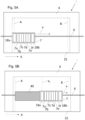
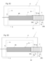
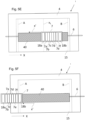
- Fig. 5A-5F schematically show a method for applying an image onto a recording medium according to a first example of the invention.
- Fig 5A shows a top view of a printer 1.
- the printer comprises a medium support 4 carrying a recording medium 15.
- the printer 1 further comprises a print unit 7 comprising print heads 7a-7.
- the printer 1 further comprises curing unit 18, which comprises two UV lamps 18a, 18b
- the print unit 7 and the curing unit 18 move in a forward scanning direction x.
- one or more print heads 7a-7f eject ink onto the recording medium 15, thereby forming an image 40 onto the recording medium 15.
- the formation of the image 40 onto the recording medium start at first side edge A of the recording medium.
- the ink applied onto the recording medium 15 is irradiated by first UV lamp 18a.
- the output of the first UV lamp 18a is controlled to follow an output profile.
- Fig. 5B the print unit 7 has advanced further in the forward scanning direction x movement, the image 40 is formed onto the recording medium 15.
- the first UV lamp 18a is now at position x 1 in the main scanning direction X.
- the print unit 7 has advanced even further in the forward scanning direction x movement, the image 40 is formed onto the recording medium 15.
- the first UV lamp 18a has reached the second side edge B of the recording medium.
- the print unit is moving in the backward scanning direction x'.
- one or more print heads 7a-7f eject ink onto the recording medium 15, thereby forming an image 40 onto the recording medium 15.
- the formation of the image 40 onto the recording medium start at second side edge B of the recording medium.
- the ink applied onto the recording medium 15 is irradiated by second UV lamp 18b.
- the output of the second UV lamp 18b is controlled to follow an output profile.
- the print heads 7a-f have not yet passed the second side edge B of the recording medium. No ink is applied onto the recording medium 15.
- the print unit 7 is moving in the backward scanning direction x'. At least one of the print heads 7a-7f is ejecting ink onto the recording medium 15, thereby forming image 40.
- the second UV lamp 18b is now at position x 1 in the main scanning direction X and emits radiation according to the predetermined output profile.
- the print unit 7 has advanced even further in the backward scanning direction x' movement, the image 40 is formed onto the recording medium 15.
- the second UV lamp 18b has reached the first side edge A of the recording medium.
- Fig. 6A-6B schematically show a method for applying an image onto a recording medium according to a second example of the invention.
- Fig 6A shows a front view of a printer 1.
- the printer comprises a medium support 4 carrying a recording medium 15.
- the printer 1 further comprises a print unit 7 comprising a plurality of print heads (not shown).
- the print unit 7 move in a forward scanning direction x.
- one or more print heads (not shown) eject ink onto the recording medium 15, thereby forming an image (not shown) onto the recording medium 15.
- the formation of the image (not shown) onto the recording medium start at first side edge A of the recording medium.
- the printer 1 further comprises curing unit 18, which is a curing unit rotatable in direction R.
- the curing unit 18 emits a beam of radiation 18' during printing.
- the curing unit rotates in direction R.
- the beam of radiation 18' moves from in the forward scanning direction x, as does the print unit 7.
- the print unit is moving in the backward scanning direction x'.
- one or more print heads (not shown) eject ink onto the recording medium 15, thereby forming an image onto the recording medium 15.
- the formation of the image 40 (not shown) onto the recording medium start at second side edge B of the recording medium.
- the curing unit is rotated in direction R'.
- the rotation of the curing unit 18 in direction R' causes the beam of radiation 18' to move in the backward scanning direction x', as does the print unit 7.
- the output of the curing unit 18 is controlled to follow an output profile. Examples of output profiled are further explained in Fig. 9A, 9B and 10A, 10B .
- the time interval between the first passage and the subsequent (second) passage is relatively long.
- the output of the curing unit is relatively low.
- the output of the curing unit 18 during the forward scanning movement, when the print unit 7 passes first side edge A is equal to the minimum output.
- Fig. 7A-7B schematically show a method for applying an image onto a recording medium according to a third example of the invention.
- FIG. 7A shows a schematic side view of a third example of the method according to present invention
- Fig. 7B shows a schematic top view of a third example of the method according to the present invention
- a scanning print unit 7 is provided to move in reciprocation in a scanning direction (x/x').
- the scanning print unit is positioned above a recording medium 15.
- the recording medium 15 is supported by the medium support 4.
- the recording medium 15 is moved in a medium transport direction (TD), perpendicular to the scanning direction (x/x').
- the medium transport direction is also referred to as transport direction or direction of recording medium transport.
- the scanning print unit 7 during printing applies ink (not shown) onto the recording medium 15, thereby forming an image swath 40.
- the image swath 40 is the swath that is printed by the scanning print unit 7 in the example shown in Fig. 7B . It is referred to as the current swath.
- the recording medium 15 may move in the transport direction TD and a subsequent swath may be formed. By forming a plurality of swaths, an image may be formed on the recording medium 15.
- a page-wide curing array 18 is provided.
- the page-wide curing array is configured to in operation emit radiation S.
- the radiation S emitted is directed towards the first mirror element 20.
- the first mirror element 20 is a flat mirror.
- the first mirror element may have a different shape.
- the radiation S emitted by the page-wide curing array 10 is reflected by the first mirror element 20.
- the radiation is reflected towards the second mirror element 21, in a direction S'.
- the radiation reflected towards the second mirror element 21 is reflected by the second mirror element 21 towards an area of the recording medium that is part of a present swath 40.
- the second mirror element 21 is connected to the page-wide curing array.
- the second mirror element 21 may be connected to other parts of the printer, such as the frame of the printer.
- the connection is schematically depicted by dashed lines 23.
- the second mirror element 21 may be movable with respect to the page-wide curing array 18.
- the page-wide curing unit 18 may in operation emit radiation over the entire width of the recording medium 15.
- the output of the curing unit 18 is controlled to follow an output profile. Consequently, the output of the curing unit 18 may change in time. Examples of output profiled are further explained in Fig. 9A, 9B and 10A, 10B .
- the time interval between the first passage and the subsequent (second) passage is relatively long.
- the output of the curing unit is relatively low.
- the output of the curing unit 18 during the forward scanning movement, when the print unit 7 passes first side edge A is equal to the minimum output.
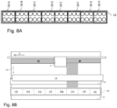
- Fig. 8A-8B schematically show a method for applying an image onto a recording medium according to a fourth example of the invention.
- Fig. 8A shows a perspective view of page-wide curing array 18.
- the page-wide curing array 18 comprises 8 segments 18c-18j that are individually controllable. One or more of the segments 18c-18j may emit radiation, while one or more of the other segments 18c-18j may not emit radiation. Further, the output of one of the segments 18c-18j emitting radiation may differ from the output of another one of the segments 18c-18j emitting radiation.
- Fig. 8B shows a top view of a printer provided with the curing unit 18 as shown in Fig. 8A . In Fig 8B , the print unit 7 is moving in the backward scanning direction x'.
- the segment 18h is emitting radiation, whereas the other segments 18c-g, 18i and 18j are not.
- the segment 18h may stop emitting radiation, whereas segment 18g may start emitting radiation, etc.
- the output of an individual segment may differ from the output of a segment upstream or downstream of said individual segment. Examples of output profiled are further explained in Fig. 9A, 9B and 10A, 10B .
- the time interval between the first passage and the subsequent (second) passage is relatively long.
- the output of the curing unit is relatively low.
- the output of the curing unit 18 during the forward scanning movement, when the print unit 7 passes first side edge A is equal to the minimum output.
- Fig. 9A and 9B show an example of a radiation output profile according to a first example in accordance with the present invention.
- Fig. 9A shows an output profile for a curing unit when the print unit moves in the forward scanning direction x.
- the first UV lamp 18a as shown in Fig. 5A-5C may have an output profile as shown in Fig. 9A .
- curing unit 18 as shown in Fig 6a , Fig. 7A and Fig. 8A may have an output profile as shown in Fig. 9A when the print unit moves in forward scanning direction x.
- the output profile will be further explained with reference to Fig. 5A - Fig. 5C .
- the output of the first UV lamp 18a is the minimum output (O min ).
- the print unit 7 When the print unit 7 has reached the end of the forward scanning movement x, the print unit 7 may turn and start moving in the backward scanning direction x'. This is schematically depicted in Fig. 5D-5F and the corresponding output profile of the second UV lamp 18b is shown in Fig. 9B .
- the output of the second UV lamp 18b is the minimum output (O min ). This corresponds to the situation shown in Fig. 5D .
- the output of the second UV lamp 18b gradually increases.
- the output is O' 1 . This corresponds to the situation schematically shown in Fig. 5E .
- the second UV lamp 18b Upon further advancing in the backward scanning direction x', the second UV lamp 18b finally reaches the first side edge A of the recording medium, as is schematically depicted in Fig. 5F .
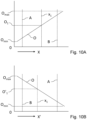
- Fig. 10A and 10B show an example of a radiation output profile according to a second example in accordance with the present invention.
- Fig. 10A and 10B will be further explained with reference to Fig. 5D-Fig. 5F , but it is noted that also curing unit 18 as shown in Fig 6A-6B , Fig. 7A-7B and Fig. 8A-8B may have an output profile as shown in Fig. 10A when the print unit moves in forward scanning direction x, or an output profile as shown in Fig. 10B when the print unit moves in backward scanning direction x'.
- Fig. 10A shows an output profile for the first UV lamp 18a during a forward movement in the main scanning direction, as shown in Fig. 5A-5C .
- the output of the first UV lamp 18a is the minimum output (O min ). This corresponds to the situation shown in Fig. 5A .
- the output of the first UV lamp 18a gradually increases.
- the first UV lamp 18a is at position x 1 , the output is O 1 .
- the first UV lamp 18a Upon further advancing in the forward scanning direction x, the first UV lamp 18a finally reaches the second side edge B of the recording medium, as is schematically depicted in Fig. 5C .
- the output of first UV lamp 18a is the maximum output O max .
- the print unit 7 When the print unit 7 has reached the end of the forward scanning movement x, the print unit 7 may turn and start moving in the backward scanning direction x'. This is schematically depicted in Fig. 5D-5F and the corresponding output profile of the second UV lamp 18b is shown in Fig. 10B .
- the output of the second UV lamp 18b is the minimum output (O min ). This corresponds to the situation shown in Fig. 5D .
- the output of the second UV lamp 18b gradually increases.
- the output is O' 1 .
- the second UV lamp 18b Upon further advancing in the backward scanning direction x', the second UV lamp 18b finally reaches the first side edge A of the recording medium, as is schematically depicted in Fig. 5F .
- the output of second UV lamp 18b is the maximum output O max .
- the output profile shown in Fig. 9A and 9B is a non-linear output profile, in which the intensity increases slowly at the start of a forward or backward movement in the scanning direction and increases faster at the end of a forward or backward movement in the scanning direction.
- the output profile shown in Fig. 10A and 10B is a linear output profile, wherein the output increases at a constant rate during a forward or backward scanning movement.
- plurality is defined as two or more than two.
- another is defined as at least a second or more.
- the terms including and/or having, as used herein, are defined as comprising (i.e., open language).
- coupled is defined as connected, although not necessarily directly.
Landscapes
- Health & Medical Sciences (AREA)
- General Health & Medical Sciences (AREA)
- Toxicology (AREA)
- Ink Jet (AREA)
Applications Claiming Priority (1)
| Application Number | Priority Date | Filing Date | Title |
|---|---|---|---|
| EP23189448 | 2023-08-03 |
Publications (1)
| Publication Number | Publication Date |
|---|---|
| EP4501653A1 true EP4501653A1 (de) | 2025-02-05 |
Family
ID=87556182
Family Applications (1)
| Application Number | Title | Priority Date | Filing Date |
|---|---|---|---|
| EP24189858.4A Pending EP4501653A1 (de) | 2023-08-03 | 2024-07-19 | Verfahren zum aufbringen eines bildes auf ein aufzeichnungsmedium, abtastdrucker und softwareprodukt |
Country Status (2)
| Country | Link |
|---|---|
| US (1) | US20250074077A1 (de) |
| EP (1) | EP4501653A1 (de) |
Citations (5)
| Publication number | Priority date | Publication date | Assignee | Title |
|---|---|---|---|---|
| US20040141040A1 (en) * | 2002-12-13 | 2004-07-22 | Konica Minolta Holdings, Inc. | Ink jet recording apparatus and ink jet recording method |
| US20090244230A1 (en) * | 2008-02-29 | 2009-10-01 | Mimaki Engineering Co., Ltd. | Ultraviolet curing inkjet printer, printing method used in ultraviolet curing inkjet printer, and head |
| US20180281310A1 (en) * | 2017-03-29 | 2018-10-04 | Xerox Corporation | In-line detection and correction of underperforming light emitting diodes in a curing station of a three dimensional object printer |
| EP3412471A1 (de) * | 2017-06-07 | 2018-12-12 | OCE Holding B.V. | Tintenstrahldruckeranordnung und verfahren zum betrieb einer tintenstrahldruckeranordnung |
| US20210031541A1 (en) * | 2019-07-29 | 2021-02-04 | Daisuke Mezaki | Liquid discharge apparatus, liquid discharge method, and non-transitory recording medium |
-
2024
- 2024-07-19 EP EP24189858.4A patent/EP4501653A1/de active Pending
- 2024-07-29 US US18/787,661 patent/US20250074077A1/en active Pending
Patent Citations (5)
| Publication number | Priority date | Publication date | Assignee | Title |
|---|---|---|---|---|
| US20040141040A1 (en) * | 2002-12-13 | 2004-07-22 | Konica Minolta Holdings, Inc. | Ink jet recording apparatus and ink jet recording method |
| US20090244230A1 (en) * | 2008-02-29 | 2009-10-01 | Mimaki Engineering Co., Ltd. | Ultraviolet curing inkjet printer, printing method used in ultraviolet curing inkjet printer, and head |
| US20180281310A1 (en) * | 2017-03-29 | 2018-10-04 | Xerox Corporation | In-line detection and correction of underperforming light emitting diodes in a curing station of a three dimensional object printer |
| EP3412471A1 (de) * | 2017-06-07 | 2018-12-12 | OCE Holding B.V. | Tintenstrahldruckeranordnung und verfahren zum betrieb einer tintenstrahldruckeranordnung |
| US20210031541A1 (en) * | 2019-07-29 | 2021-02-04 | Daisuke Mezaki | Liquid discharge apparatus, liquid discharge method, and non-transitory recording medium |
Also Published As
| Publication number | Publication date |
|---|---|
| US20250074077A1 (en) | 2025-03-06 |
Similar Documents
| Publication | Publication Date | Title |
|---|---|---|
| KR101399027B1 (ko) | 화상 형성 장치 및 화상 형성 방법 | |
| US8764153B2 (en) | Inkjet recording apparatus and image forming method | |
| WO2006087949A1 (ja) | インクジェット記録装置及びインクジェット記録方法 | |
| EP1627746B1 (de) | Druckvorrichtung mit Strahlungsquelle | |
| US20180345682A1 (en) | Printer and method for operating a printer | |
| CN102858543B (zh) | 图像形成装置以及图像形成方法 | |
| US12403702B2 (en) | Method and printer for printing and curing an image | |
| EP4501653A1 (de) | Verfahren zum aufbringen eines bildes auf ein aufzeichnungsmedium, abtastdrucker und softwareprodukt | |
| JP2018043438A (ja) | インクジェットプリンタ及びキャリッジの移動制御方法 | |
| US20250346049A1 (en) | Method for operating a printing apparatus, printing apparatus and software product | |
| US20250360743A1 (en) | Method for operating a printing apparatus, printing apparatus and software product | |
| US20250375970A1 (en) | Method for operating a printing apparatus, printing apparatus and software product | |
| US20240262108A1 (en) | Method for operating a printing apparatus, printing apparatus and software product | |
| US20230406008A1 (en) | Printer apparatus and print method for preparing an image having matt portions and glossy portions | |
| US12384171B2 (en) | Method for enhancing adhesion of a UV curable ink | |
| JP2012106392A (ja) | 描画装置および描画装置の制御方法 | |
| EP4684975A1 (de) | Drucker und druckverfahren | |
| US20240309232A1 (en) | Radiation-curable ink composition, method for preparing the same and method for applying an image onto a recording medium | |
| EP3395582B1 (de) | Drucker und verfahren zum betrieb eines druckers | |
| JP2009096060A (ja) | 記録装置および液体噴射装置 | |
| JP2018030320A (ja) | インクジェットプリンタ及びキャリッジの移動制御方法 | |
| JP2006231757A (ja) | インクジェット記録装置 |
Legal Events
| Date | Code | Title | Description |
|---|---|---|---|
| PUAI | Public reference made under article 153(3) epc to a published international application that has entered the european phase |
Free format text: ORIGINAL CODE: 0009012 |
|
| STAA | Information on the status of an ep patent application or granted ep patent |
Free format text: STATUS: THE APPLICATION HAS BEEN PUBLISHED |
|
| AK | Designated contracting states |
Kind code of ref document: A1 Designated state(s): AL AT BE BG CH CY CZ DE DK EE ES FI FR GB GR HR HU IE IS IT LI LT LU LV MC ME MK MT NL NO PL PT RO RS SE SI SK SM TR |
|
| STAA | Information on the status of an ep patent application or granted ep patent |
Free format text: STATUS: REQUEST FOR EXAMINATION WAS MADE |
|
| 17P | Request for examination filed |
Effective date: 20250805 |