EP4501700A1 - Ensemble câble de charge et système de charge de véhicule électrique - Google Patents
Ensemble câble de charge et système de charge de véhicule électrique Download PDFInfo
- Publication number
- EP4501700A1 EP4501700A1 EP23189082.3A EP23189082A EP4501700A1 EP 4501700 A1 EP4501700 A1 EP 4501700A1 EP 23189082 A EP23189082 A EP 23189082A EP 4501700 A1 EP4501700 A1 EP 4501700A1
- Authority
- EP
- European Patent Office
- Prior art keywords
- charging
- charging cable
- arm
- cable assembly
- electric vehicle
- Prior art date
- Legal status (The legal status is an assumption and is not a legal conclusion. Google has not performed a legal analysis and makes no representation as to the accuracy of the status listed.)
- Withdrawn
Links
Images

Classifications
-
- B—PERFORMING OPERATIONS; TRANSPORTING
- B60—VEHICLES IN GENERAL
- B60L—PROPULSION OF ELECTRICALLY-PROPELLED VEHICLES; SUPPLYING ELECTRIC POWER FOR AUXILIARY EQUIPMENT OF ELECTRICALLY-PROPELLED VEHICLES; ELECTRODYNAMIC BRAKE SYSTEMS FOR VEHICLES IN GENERAL; MAGNETIC SUSPENSION OR LEVITATION FOR VEHICLES; MONITORING OPERATING VARIABLES OF ELECTRICALLY-PROPELLED VEHICLES; ELECTRIC SAFETY DEVICES FOR ELECTRICALLY-PROPELLED VEHICLES
- B60L53/00—Methods of charging batteries, specially adapted for electric vehicles; Charging stations or on-board charging equipment therefor; Exchange of energy storage elements in electric vehicles
- B60L53/30—Constructional details of charging stations
- B60L53/302—Cooling of charging equipment
-
- B—PERFORMING OPERATIONS; TRANSPORTING
- B60—VEHICLES IN GENERAL
- B60L—PROPULSION OF ELECTRICALLY-PROPELLED VEHICLES; SUPPLYING ELECTRIC POWER FOR AUXILIARY EQUIPMENT OF ELECTRICALLY-PROPELLED VEHICLES; ELECTRODYNAMIC BRAKE SYSTEMS FOR VEHICLES IN GENERAL; MAGNETIC SUSPENSION OR LEVITATION FOR VEHICLES; MONITORING OPERATING VARIABLES OF ELECTRICALLY-PROPELLED VEHICLES; ELECTRIC SAFETY DEVICES FOR ELECTRICALLY-PROPELLED VEHICLES
- B60L53/00—Methods of charging batteries, specially adapted for electric vehicles; Charging stations or on-board charging equipment therefor; Exchange of energy storage elements in electric vehicles
- B60L53/10—Methods of charging batteries, specially adapted for electric vehicles; Charging stations or on-board charging equipment therefor; Exchange of energy storage elements in electric vehicles characterised by the energy transfer between the charging station and the vehicle
- B60L53/14—Conductive energy transfer
- B60L53/16—Connectors, e.g. plugs or sockets, specially adapted for charging electric vehicles
-
- B—PERFORMING OPERATIONS; TRANSPORTING
- B60—VEHICLES IN GENERAL
- B60L—PROPULSION OF ELECTRICALLY-PROPELLED VEHICLES; SUPPLYING ELECTRIC POWER FOR AUXILIARY EQUIPMENT OF ELECTRICALLY-PROPELLED VEHICLES; ELECTRODYNAMIC BRAKE SYSTEMS FOR VEHICLES IN GENERAL; MAGNETIC SUSPENSION OR LEVITATION FOR VEHICLES; MONITORING OPERATING VARIABLES OF ELECTRICALLY-PROPELLED VEHICLES; ELECTRIC SAFETY DEVICES FOR ELECTRICALLY-PROPELLED VEHICLES
- B60L53/00—Methods of charging batteries, specially adapted for electric vehicles; Charging stations or on-board charging equipment therefor; Exchange of energy storage elements in electric vehicles
- B60L53/10—Methods of charging batteries, specially adapted for electric vehicles; Charging stations or on-board charging equipment therefor; Exchange of energy storage elements in electric vehicles characterised by the energy transfer between the charging station and the vehicle
- B60L53/14—Conductive energy transfer
- B60L53/18—Cables specially adapted for charging electric vehicles
-
- B—PERFORMING OPERATIONS; TRANSPORTING
- B60—VEHICLES IN GENERAL
- B60L—PROPULSION OF ELECTRICALLY-PROPELLED VEHICLES; SUPPLYING ELECTRIC POWER FOR AUXILIARY EQUIPMENT OF ELECTRICALLY-PROPELLED VEHICLES; ELECTRODYNAMIC BRAKE SYSTEMS FOR VEHICLES IN GENERAL; MAGNETIC SUSPENSION OR LEVITATION FOR VEHICLES; MONITORING OPERATING VARIABLES OF ELECTRICALLY-PROPELLED VEHICLES; ELECTRIC SAFETY DEVICES FOR ELECTRICALLY-PROPELLED VEHICLES
- B60L50/00—Electric propulsion with power supplied within the vehicle
- B60L50/50—Electric propulsion with power supplied within the vehicle using propulsion power supplied by batteries or fuel cells
-
- Y—GENERAL TAGGING OF NEW TECHNOLOGICAL DEVELOPMENTS; GENERAL TAGGING OF CROSS-SECTIONAL TECHNOLOGIES SPANNING OVER SEVERAL SECTIONS OF THE IPC; TECHNICAL SUBJECTS COVERED BY FORMER USPC CROSS-REFERENCE ART COLLECTIONS [XRACs] AND DIGESTS
- Y02—TECHNOLOGIES OR APPLICATIONS FOR MITIGATION OR ADAPTATION AGAINST CLIMATE CHANGE
- Y02T—CLIMATE CHANGE MITIGATION TECHNOLOGIES RELATED TO TRANSPORTATION
- Y02T10/00—Road transport of goods or passengers
- Y02T10/60—Other road transportation technologies with climate change mitigation effect
- Y02T10/70—Energy storage systems for electromobility, e.g. batteries
-
- Y—GENERAL TAGGING OF NEW TECHNOLOGICAL DEVELOPMENTS; GENERAL TAGGING OF CROSS-SECTIONAL TECHNOLOGIES SPANNING OVER SEVERAL SECTIONS OF THE IPC; TECHNICAL SUBJECTS COVERED BY FORMER USPC CROSS-REFERENCE ART COLLECTIONS [XRACs] AND DIGESTS
- Y02—TECHNOLOGIES OR APPLICATIONS FOR MITIGATION OR ADAPTATION AGAINST CLIMATE CHANGE
- Y02T—CLIMATE CHANGE MITIGATION TECHNOLOGIES RELATED TO TRANSPORTATION
- Y02T10/00—Road transport of goods or passengers
- Y02T10/60—Other road transportation technologies with climate change mitigation effect
- Y02T10/7072—Electromobility specific charging systems or methods for batteries, ultracapacitors, supercapacitors or double-layer capacitors
-
- Y—GENERAL TAGGING OF NEW TECHNOLOGICAL DEVELOPMENTS; GENERAL TAGGING OF CROSS-SECTIONAL TECHNOLOGIES SPANNING OVER SEVERAL SECTIONS OF THE IPC; TECHNICAL SUBJECTS COVERED BY FORMER USPC CROSS-REFERENCE ART COLLECTIONS [XRACs] AND DIGESTS
- Y02—TECHNOLOGIES OR APPLICATIONS FOR MITIGATION OR ADAPTATION AGAINST CLIMATE CHANGE
- Y02T—CLIMATE CHANGE MITIGATION TECHNOLOGIES RELATED TO TRANSPORTATION
- Y02T90/00—Enabling technologies or technologies with a potential or indirect contribution to GHG emissions mitigation
- Y02T90/10—Technologies relating to charging of electric vehicles
- Y02T90/12—Electric charging stations
Definitions
- European patent application no. EP 4 134 266 A1 describes an electric vehicle charging system according to the current state of the art, the system having a liquid-cooling system for cooling the charging cable and/or the charging connector.
- the electric vehicle charging system includes a charging station which houses thermal management unit comprising a vapour-compression refrigeration system.
- the liquid-cooled charging cable and/or charging connector allows for an electric vehicle to be charged with a higher electric current, without exceeding a temperature limit of the system.
- a charging cable assembly for charging an electric vehicle.
- the charging cable assembly includes an arm, a charging cable having a first end and a second end, the charging cable comprising a plurality of conductors extending from the first end to the second end and a plurality of coolant channels extending from the first end to the second end, wherein the first end of the charging cable is connected to the arm, a charging connector provided at the second end of the charging cable, the charging connector being configured for electrically connecting the charging cable assembly to an electric vehicle, and a thermal management unit mounted on the arm, the thermal management unit being configured for cooling the charging cable and/or the charging connector by circulating coolant through the plurality of coolant channels.
- an electric vehicle charging system includes a charging station including an electric vehicle supply equipment (EVSE) apparatus, and a charging cable assembly according to the first aspect.
- EVSE electric vehicle supply equipment
- a charging cable assembly for charging an electric vehicle is provided.
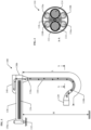
- Fig. 1 shows a side view of an exemplary charging cable assembly 100.
- the exemplary charging cable assembly 100 includes an arm 130 having a fixed end portion 130a and a free end portion 130b, and a charging cable 110 having a first end 110a and a second end 110b.
- the first end 110a of the charging cable 110 is exemplarily connected to the free end portion 130b of the arm 130 such that the charging cable 110 hangs from the arm 130.
- the term “fixed end portion” refers to the portion of the arm at which the arm is supported, and the term “free end portion” refers to the portion of the arm which is not supported.
- the "fixed end portion” may be supported such that the arm is mounted at the fixed end portion to restrict translation, but may be allowed to rotate in at least one degree of freedom.
- portion of the "fixed end portion” and the “free end portion” refers to the respective end portion of the arm, more particularly, the respective end 25% of the arm. In other words, the "fixed end portion” refers to the 25% of the arm at the end which is supported, while the “free end portion” refers to the 25% of the arm at the end which is not supported.
- the arrangement of coolant channels 116 is exemplarily shown as comprising four coolant channels 116 which form two separate circuits for coolant flow, whereby the outbound cooling channels 116a connect at the second end of the charging cable to the respective inbound cooling channels 116b to form each cooling circuit.
- the present disclosure is not limited to any specific arrangement of conductors and coolant channels, and may include any number of conductors, any number of coolant channels, and any configuration of cooling circuits therein.
- the arm 130 may form a rigid, hollow structure through which components may pass through.
- the charging cable 110 may, for example, pass through the arm 130 and continue to a charging station.
- the arm 130 may include a plurality of busbars 134, and each one of the plurality of conductors 114 of the charging cable 110 are electrically connected to each respective one of the plurality of busbars 134. Since the arm 130 is rigid, and may be made to be electrically isolating, a significant length of the charging cable 110 can be replaced with low-resistance busbars 134 which generate significantly less heat at high current throughput, and consequently require no additional cooling.
- the arm 130 may be configured to be mounted to a wall, a ceiling, or a charging station.
- the fixed end portion 130a of the arm 130 may be configured to be mounted to a wall, a ceiling or a charging station.
- the arm 130 may be configured to be mounted to a side surface or a top surface of a charging station.
- the charging cable assembly 100 shown in Fig. 1 the charging cable assembly 100 is exemplarily shown as being attached to a horizontal surface, which would correspond to the top surface of a charging station in a typical installation.
- the charging cable assembly 100 may be mounted to a wall or ceiling, with additional busbars and/or cables connecting the charging cable assembly 100 to the charging station.
- the electric vehicle charging system 300 includes a charging station 320 which includes an electric vehicle supply equipment (EVSE) apparatus 322, and a charging cable assembly 100 according to the first aspect of the present disclosure.
- the electric vehicle charging system 300 in simplest form, may consist of a charging station 320 with a charging cable assembly 100 mounted to the top surface, forming a self-contained electric vehicle charging system 300 having an articulated arm 130 and a liquid cooled charging cable 110 which is cooled by the arm-mounted thermal management unit 140.
Landscapes
- Engineering & Computer Science (AREA)
- Power Engineering (AREA)
- Transportation (AREA)
- Mechanical Engineering (AREA)
- Electric Propulsion And Braking For Vehicles (AREA)
- Charge And Discharge Circuits For Batteries Or The Like (AREA)
Priority Applications (1)
| Application Number | Priority Date | Filing Date | Title |
|---|---|---|---|
| EP23189082.3A EP4501700A1 (fr) | 2023-08-01 | 2023-08-01 | Ensemble câble de charge et système de charge de véhicule électrique |
Applications Claiming Priority (1)
| Application Number | Priority Date | Filing Date | Title |
|---|---|---|---|
| EP23189082.3A EP4501700A1 (fr) | 2023-08-01 | 2023-08-01 | Ensemble câble de charge et système de charge de véhicule électrique |
Publications (1)
| Publication Number | Publication Date |
|---|---|
| EP4501700A1 true EP4501700A1 (fr) | 2025-02-05 |
Family
ID=87553649
Family Applications (1)
| Application Number | Title | Priority Date | Filing Date |
|---|---|---|---|
| EP23189082.3A Withdrawn EP4501700A1 (fr) | 2023-08-01 | 2023-08-01 | Ensemble câble de charge et système de charge de véhicule électrique |
Country Status (1)
| Country | Link |
|---|---|
| EP (1) | EP4501700A1 (fr) |
Citations (4)
| Publication number | Priority date | Publication date | Assignee | Title |
|---|---|---|---|---|
| US5306999A (en) * | 1993-01-15 | 1994-04-26 | Hubbell Incorporated | Electric vehicle charging station |
| US20170028862A1 (en) * | 2015-07-29 | 2017-02-02 | Dr. Ing. H.C. F. Porsche Aktiengesellschaft | Charging station having a charging cable |
| EP4134266A1 (fr) | 2021-08-13 | 2023-02-15 | ABB E-mobility B.V. | Station de chargement de véhicule électrique |
| EP3708412B1 (fr) * | 2019-03-12 | 2023-07-05 | ABB E-mobility B.V. | Agencement de charge pour alimenter un véhicule électrique en énergie électrique |
-
2023
- 2023-08-01 EP EP23189082.3A patent/EP4501700A1/fr not_active Withdrawn
Patent Citations (4)
| Publication number | Priority date | Publication date | Assignee | Title |
|---|---|---|---|---|
| US5306999A (en) * | 1993-01-15 | 1994-04-26 | Hubbell Incorporated | Electric vehicle charging station |
| US20170028862A1 (en) * | 2015-07-29 | 2017-02-02 | Dr. Ing. H.C. F. Porsche Aktiengesellschaft | Charging station having a charging cable |
| EP3708412B1 (fr) * | 2019-03-12 | 2023-07-05 | ABB E-mobility B.V. | Agencement de charge pour alimenter un véhicule électrique en énergie électrique |
| EP4134266A1 (fr) | 2021-08-13 | 2023-02-15 | ABB E-mobility B.V. | Station de chargement de véhicule électrique |
Similar Documents
| Publication | Publication Date | Title |
|---|---|---|
| US12552274B2 (en) | Liquid cooled charging cable system | |
| JP7670710B2 (ja) | 電気自動車とともに使用される双方向電力変換及び充電用の装置 | |
| EP3700022A1 (fr) | Ensemble connecteur électrique présentant des caractéristiques de refroidissement modulaires | |
| US10800276B2 (en) | Electrical charging arrangement with charging socket for vehicle | |
| JP6048572B2 (ja) | 無停電電源装置 | |
| EP3793038B1 (fr) | Ensemble connecteur électrique | |
| US20200313328A1 (en) | Electrical connector assembly with liquid cooling features | |
| EP3950407B1 (fr) | Batterie d'alimentation montée sur véhicule, système de stockage d'énergie rechargeable et voiture électrique | |
| CN110869238A (zh) | 用于为至少一个可电驱动的机动车的充放电过程提供电能的电蓄存设备以及加装模块和运行方法 | |
| US11440491B2 (en) | Vehicle cooling system and wire harness cooling structure | |
| US12334233B2 (en) | Cooled charging cable | |
| US20190140525A1 (en) | Conductor arrangement and transportable electrical drive device | |
| KR20210055001A (ko) | 전기차 충전용 케이블 어셈블리 | |
| US11837824B2 (en) | Systems, methods, and apparatus useful for busway power distribution | |
| US20230299512A1 (en) | Hybrid electric charging inlet | |
| CN114864168A (zh) | 线缆、充电枪及充电桩 | |
| EP4501700A1 (fr) | Ensemble câble de charge et système de charge de véhicule électrique | |
| WO2022148763A1 (fr) | Entrée de charge | |
| CN114822927B (zh) | 一种小线径液冷线和充电装置 | |
| JP2021197334A (ja) | 冷却装置、及び、バッテリモジュールアッセンブリ | |
| KR102240921B1 (ko) | 전지팩 | |
| CN223378894U (zh) | 一种充电装置及充电系统 | |
| US20260011994A1 (en) | Fluid-cooled busbar assembly for a track busway system | |
| US20250246862A1 (en) | Active Cooling of Busbars Using Compressed Air | |
| CN216751203U (zh) | 一种车载多路输入输出综合电源系统 |
Legal Events
| Date | Code | Title | Description |
|---|---|---|---|
| PUAI | Public reference made under article 153(3) epc to a published international application that has entered the european phase |
Free format text: ORIGINAL CODE: 0009012 |
|
| STAA | Information on the status of an ep patent application or granted ep patent |
Free format text: STATUS: THE APPLICATION HAS BEEN PUBLISHED |
|
| AK | Designated contracting states |
Kind code of ref document: A1 Designated state(s): AL AT BE BG CH CY CZ DE DK EE ES FI FR GB GR HR HU IE IS IT LI LT LU LV MC ME MK MT NL NO PL PT RO RS SE SI SK SM TR |
|
| STAA | Information on the status of an ep patent application or granted ep patent |
Free format text: STATUS: THE APPLICATION IS DEEMED TO BE WITHDRAWN |
|
| 18D | Application deemed to be withdrawn |
Effective date: 20250806 |