EP4501754A1 - Structure de carrosserie de véhicule et procédé de conception d'une structure de carrosserie de véhicule - Google Patents
Structure de carrosserie de véhicule et procédé de conception d'une structure de carrosserie de véhicule Download PDFInfo
- Publication number
- EP4501754A1 EP4501754A1 EP23779059.7A EP23779059A EP4501754A1 EP 4501754 A1 EP4501754 A1 EP 4501754A1 EP 23779059 A EP23779059 A EP 23779059A EP 4501754 A1 EP4501754 A1 EP 4501754A1
- Authority
- EP
- European Patent Office
- Prior art keywords
- side sill
- vehicle body
- overlapping portion
- center pillar
- center
- Prior art date
- Legal status (The legal status is an assumption and is not a legal conclusion. Google has not performed a legal analysis and makes no representation as to the accuracy of the status listed.)
- Pending
Links
Images





Classifications
-
- B—PERFORMING OPERATIONS; TRANSPORTING
- B62—LAND VEHICLES FOR TRAVELLING OTHERWISE THAN ON RAILS
- B62D—MOTOR VEHICLES; TRAILERS
- B62D25/00—Superstructure or monocoque structure sub-units; Parts or details thereof not otherwise provided for
- B62D25/02—Side panels
-
- B—PERFORMING OPERATIONS; TRANSPORTING
- B62—LAND VEHICLES FOR TRAVELLING OTHERWISE THAN ON RAILS
- B62D—MOTOR VEHICLES; TRAILERS
- B62D21/00—Understructures, i.e. chassis frame on which a vehicle body may be mounted
- B62D21/15—Understructures, i.e. chassis frame on which a vehicle body may be mounted having impact absorbing means, e.g. a frame designed to permanently or temporarily change shape or dimension upon impact with another body
- B62D21/157—Understructures, i.e. chassis frame on which a vehicle body may be mounted having impact absorbing means, e.g. a frame designed to permanently or temporarily change shape or dimension upon impact with another body for side impacts
-
- B—PERFORMING OPERATIONS; TRANSPORTING
- B62—LAND VEHICLES FOR TRAVELLING OTHERWISE THAN ON RAILS
- B62D—MOTOR VEHICLES; TRAILERS
- B62D25/00—Superstructure or monocoque structure sub-units; Parts or details thereof not otherwise provided for
- B62D25/02—Side panels
- B62D25/025—Side sills thereof
-
- B—PERFORMING OPERATIONS; TRANSPORTING
- B62—LAND VEHICLES FOR TRAVELLING OTHERWISE THAN ON RAILS
- B62D—MOTOR VEHICLES; TRAILERS
- B62D25/00—Superstructure or monocoque structure sub-units; Parts or details thereof not otherwise provided for
- B62D25/04—Door pillars ; windshield pillars
-
- B—PERFORMING OPERATIONS; TRANSPORTING
- B62—LAND VEHICLES FOR TRAVELLING OTHERWISE THAN ON RAILS
- B62D—MOTOR VEHICLES; TRAILERS
- B62D27/00—Connections between superstructure or understructure sub-units
- B62D27/02—Connections between superstructure or understructure sub-units rigid
- B62D27/023—Assembly of structural joints
Definitions
- the present invention relates to a vehicle body structure and a method for designing the vehicle body structure.
- a vehicle body of a passenger car which is a type of a vehicle, usually includes a center pillar arranged along the vertical direction of the vehicle body, and a side sill that is connected to a lower portion of the center pillar and is arranged along the front and rear direction of the vehicle body (for example, refer to Patent Documents 1 and 2).
- the lower portion of the center pillar and the side sill are firmly fixed to each other by welding or the like. Then, when the passenger car has a side collision, the center pillar and the side sill work together to receive impact loads, thereby absorbing the impact and protecting occupants in a cabin.
- One of the objectives of the present invention is to provide a lighter-weight vehicle body structure while achieving a high anti-side impact performance.
- the gist of the present invention is the following vehicle body structure.
- a lighter-weight vehicle body structure can be realized while achieving a high anti-side collision performance.
- the present inventors focused on the combined structure between a center pillar and a side sill. Specifically, the focus was put on the fact that the amount of intrusion of the side sill and the center pillar toward the inside in a vehicle width direction at a side collision of an automobile is subject to the following two kinds of influence (a) and (b).
- the present inventors conducted extensive studies on the basis of the findings (a) and (b) described above, and came to the conclusion that a lighter-weight vehicle body structure can be realized while achieving a high anti-side collision performance, by improving at least one of (1) and (2) described below.
- the torsion angle of the side sill at the time of a side collision is decreased, and the amount of intrusion of the side sill toward the cabin can be suppressed at a high mass efficiency.
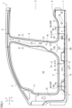
- Figure 1 is a schematic left side view illustrating a main portion of a vehicle body 1 to which a vehicle body structure according to one embodiment of the present invention is applied.
- Figure 2 is a cross-sectional view of an upper portion 21 of a center pillar 4 perpendicular to a vertical direction Z, taken along line II-II in Figure 1 , and the illustration of an inner depth side of a cross-section is omitted.
- Figure 3 is an enlarged view for describing a combined state between a side sill outer 15 and a pillar inner 42 in Figure 1 .
- Figure 4 is a schematic cross-sectional view of a main portion for describing the combined state between the side sill outer 15 and the pillar inner 42 of the center pillar 4, taken along line IV-IV in Figure 1 , and illustrates a cross-section perpendicular to a front and rear direction X.
- Figure 1 a description will be given with reference to Figure 1 to Figure 4 as appropriate.
- the vehicle body 1 is a part of a vehicle, and an automobile can be listed as the vehicle.
- a passenger car can be listed as an example of the automobile.
- a sedan-type passenger car, a coupe-type passenger car, a hatchback-type passenger car, a minivan-type passenger car, an SUV (Sport Utility Vehicle)-type passenger car, or the like can be listed.
- the vehicle body 1 is formed by using a steel sheet that has a predetermined thickness.
- the vehicle body 1 includes a front pillar 2, a roof pillar 3, the center pillar 4, a side sill 5, a side sill rear 6, floor cross members 7 and 8, and a floor panel 9.
- the cross-sectional shape in a cross-section perpendicular to the longitudinal direction of the front pillar 2 is formed into a closed shape (closed cross-sectional shape) such as a rectangle.
- the front pillar 2 includes a pillar upper 11 that extends toward the rear as it extends upward and that is coupled to the roof pillar 3, and a pillar lower 12 arranged under the pillar upper 11.
- the pillar lower 12 is formed into, for example, an L-shaped when viewed in a side view. A lower rear end edge 12a of the pillar lower 12 is opened toward the rear.
- the roof pillar 3 is arranged at a roof portion of the vehicle body 1, and extends toward the rear from the pillar upper 11.
- the side sill 5 is provided in a lower portion of an outer portion of the vehicle body 1 in a vehicle width direction Y.
- the side sill 5 is connected to a lower portion of the center pillar 4, and is arranged along a front and rear direction X of the vehicle body 1.
- the side sill 5 forms an endless closed cross-sectional shape in a cross-section perpendicular to the front and rear direction X.
- the side sill 5 includes the side sill outer 15 and a side sill inner 16 that are aligned in the vehicle width direction Y.
- the cross-sectional shape perpendicular to the front and rear direction X is formed into a hat shape, and the side sill outer 15 and the side sill inner 16 cooperate to form the closed cross-sectional shape in the side sill 5.
- the side sill outer 15 is arranged on an outer side in the vehicle width direction Y with respect to the side sill inner 16.
- the side sill outer 15 and the side sill inner 16 may not have the same thickness, it is preferable that the side sill outer 15 and the side sill inner 16 have the same thickness as in the present embodiment.
- the side sill outer 15 and the side sill inner 16 are formed of steel sheets. It is preferable that the thickness of each of these side sill outer 15 and side sill inner 16, that is, the thickness of the side sill 5, is set to, for example, 0.80 mm to 1.60 mm. The lower limit of the thickness of the side sill 5 may be 0.80 mm, may be 1.00 mm, or may be 1.20 mm.
- the upper limit of the thickness of the side sill 5 may be a value larger than 1.60 mm, may be 1.60 mm, may be 1.45 mm, or may be 1.40 mm.
- the weight of the side sill 5 can be prevented from being excessively large, while sufficiently securing the strength of the side sill 5 at the time of a side collision.
- the tensile strengths of the side sill outer 15 and the side sill inner 16 are not particularly limited, examples include values of 980 MPa or more.
- the side sill outer 15 includes an upper flange 151, an upper wall 152 extending outward in the vehicle width direction Y from the upper flange 151, a side wall 153 extending downward from the upper wall 152, a lower wall 154 extending inward in the vehicle width direction Y from the side wall 153, and a lower flange 155 extending downward from the lower wall 154.
- the upper wall 152 of the side sill outer 15 includes an upper surface 152a as an external surface facing upward. Additionally, the side wall 153 of the side sill outer 15 is arranged in an orientation along the vertical direction Z, and includes an outer surface 153a as an external surface facing outward in the vehicle width direction Y. From a viewpoint of the anti-side collision performance, there is no significant difference in the length of the side wall 153 of the side sill outer 15 in the vertical direction Z between vehicles in the A-segment, which is a relatively small vehicle type, and vehicles in the E-segment, which is a relatively large vehicle type, and SUV vehicles.
- the lower wall 154 of the side sill outer 15 includes a bottom surface 154a, which is arranged below the outer surface 153a of the side wall 153, and is an external surface in an orientation facing the ground. Further, the lower flange 155 of the side sill outer 15 projects downward from the bottom surface 154a of the lower wall 154.
- the side wall 153 and the lower wall 154 are connected to each other via an R portion 156.
- the R portion 156 is formed into a curved shape that has the center in the space surrounded by the side sill 5 in a cross-section perpendicular to the front and rear direction X.
- the R portion 156 is a part of the side wall 153, and is also a part of the lower wall 154. In a cross-section perpendicular to the front and rear direction X, a portion of the side wall 153 other than the R portion 156 extends substantially linearly upward from the upper end 156a of the R portion 156.
- a portion of the lower wall 154 other than the R portion 156 extends substantially linearly inward in the vehicle width direction Y from a lower end 156b of R portion 156.
- the lower wall 154 and the lower flange 155 are connected to each other via an R portion 157.
- the R portion 157 is formed into a curved shape that has the center outside the space surrounded by the side sill 5 in a cross-section perpendicular to the front and rear direction X.
- the R portion 157 is a part of the lower wall 154, and is also a part of the lower flange 155.
- a portion of the lower wall 154 other than the R portion 157 extends substantially linearly outward in the vehicle width direction Y from an upper end 157a of the R portion 157.
- a portion of the lower flange 155 other than the R portion 157 extends substantially linearly downward from a lower end 157b of the R portion 157.
- the upper wall 152 may be horizontal, or may be formed into an inclined shape that extends downward as it extends outward in the vehicle width direction Y.
- the lower wall 154 may be horizontal, or may be formed into an inclined shape that extends upward as it extends outward in the vehicle width direction Y.
- the side sill inner 16 includes an upper flange 161, an upper wall 162 extending inward in the vehicle width direction Y from the upper flange 161, a side wall 163 extending downward from the upper wall 162, a lower wall 164 extending outward in the vehicle width direction Y from the side wall 163, and a lower flange 165 extending downward from the lower wall 164.
- the upper wall 162 may be horizontal, or may be formed into an inclined shape that extends downward as it extends outward in the vehicle width direction Y.
- the lower wall 164 may be horizontal, or may be formed into an inclined shape that extends upward as it extends outward in the vehicle width direction Y.
- the upper flanges 151 and 161 are coupled to each other by welding, adhesion, or the like.
- the lower flanges 155 and 165 are coupled to each other by welding, adhesion, or the like.
- the floor cross members 7 and 8 extend inward in the vehicle width direction Y from the side sill inner 16.
- the floor cross members 7 and 8 are arranged on, for example, a front seat side of a vehicle room (cabin 10) formed by the vehicle body 1.
- the floor cross members 7 and 8 are arranged spaced apart in the front and rear direction X, and the floor cross member 8 is arranged behind the floor cross member 7.
- the cross-sectional shape perpendicular to the vehicle width direction Y is a hat shape, and the floor cross members 7 and 8 cooperate with the floor panel 9 to form closed cross-sectional shapes.
- the floor panel 9 forms a bottom of the cabin 10 of the vehicle body 1, and the floor cross members 7 and 8 are fixed to the floor panel 9.
- a slide rail (not illustrated) is installed on the floor cross members 7 and 8.
- the slide rail supports a sheet (not illustrated) on which an occupant sits.
- a front portion 5a of the side sill 5 is fitted to the pillar lower 12 of the front pillar 2, and is fixed to this pillar lower 12 by welding, an adhesives, or the like. Then, the side sill 5 extends rearward from the lower rear end edge 12a of the pillar lower 12. The lower rear end edge 12a of the pillar lower 12 is opened toward the rear, and is located on a flat surface perpendicular to the front and rear direction X in the present embodiment. Additionally, a rear portion 5b of the side sill 5 is fitted to the side sill rear 6, and is fixed to this side sill rear 6 by welding, an adhesive, or the like.
- the side sill rear 6 is arranged behind the side sill 5.
- the side sill rear 6 is a hollow-shell member extending along the front and rear direction X.
- the cross-sectional shape in a cross section perpendicular to the longitudinal direction of the side sill rear 6 is formed into a closed shape (closed cross-sectional shape), such as a rectangle.
- a front end edge 6a of the side sill rear 6 is opened toward the front, and is located on a flat surface perpendicular to the front and rear direction X in the present embodiment.
- the side sill 5 extends forward from the front end edge 6a of the side sill rear 6.
- the front portion 5a and the rear portion 5b of the side sill 5 are regulated from being moved inward in the vehicle width direction Y at a front restricting position X2 (X2F) and a rear restricting position X2 (X2R) by the pillar lower 12 as a mating member and the side sill rear 6 as a mating member, respectively.
- the side sill 5 When an object collides with the side sill 5 from the side, particularly, when a side collision occurs in an overlapping portion 22 between the center pillar 4 and the side sill 5, the side sill 5 receives the impact load from the object with the lower rear end edge 12a of the front pillar 2 serving as the front restricting position X2 (X2F), the overlapping portion 22 of the center pillar 4 serving as a middle restricting position, and the front end edge 6a of the side sill rear 6 serving as the rear restricting position X2 (X2R). Then, when the impact load is a constant value or more, the side sill 5 absorbs the impact load while plastically deforming inward in the width direction Y.
- the side sill rear 6 is described as a member forming the rear restricting position X2 (X2R).
- X2R rear restricting position
- other members such as a lower end portion of a C pillar connected to the rear end of the side sill 5, may form the rear restricting position X2 (X2R).
- the other members in this case include, for example, a foil house inner, a rear floor panel, and a rear cross member.
- the rear restricting position X2 (X2R) is a rear-side restraining point at the time when the side sill 5 is plastically deformed upon reception of the impact load at the time of a side collision, and the specific example of the member forming the rear restricting position X2 (X2R) is not limited.
- the specific example of the member forming the front restricting position X2 (X2F) is not limited.
- the center pillar 4 is arranged behind the front pillar 2, and is arranged along the vertical direction Z from the roof pillar 3 to the side sill 5.
- the center pillar 4 includes the upper portion 21 arranged above the side sill 5, and the overlapping portion 22 that is arranged under the upper portion 21, and that is arranged to cover an external surface of the side sill 5 at a portion connected to the side sill 5.
- the center pillar 4 includes a pillar outer 41 and a pillar inner 42 that are aligned in the vehicle width direction Y, and the upper portion 21 and the overlapping portion 22 are formed by these pillar outer 41 and pillar inner 42.
- the upper portion 21 and the overlapping portion 22 may be integrally molded.
- the integral molding in this case refers to that, in each of the pillar outer 41 and the pillar inner 42, the portions that serve as the upper portion 21 and the overlapping portion 22 are molded as a single member at the time of molding of a starting material (blank), and there is no seam between the portions that serve as the upper portion 21 and the overlapping portion 22.
- the starting material is a tailored blank, such as a steel sheet or an aluminum board, for each of the pillar outer 41 and the pillar inner 42, and the integral molding in this case also includes a configuration in which respective edge portions of the portion that serves as the upper portion 21 and the portion that serves as the overlapping portion 22 are coupled to each other by welding or the like.
- the center pillar 4 may have a constant thickness, or may be formed by press-molding a tailored blank that has different thicknesses depending on location.
- examples of the configuration include, for example, a configuration in which the thickness of an intermediate portion of the upper portion 21 of the center pillar 4 in the vertical direction Z is larger than the thickness of the other portions of the center pillar 4.
- the center pillar 4 is formed of a steel sheet.
- the thickness of the upper portion 21 of the center pillar 4 is not particularly limited, examples include about 0.80 mm to 2.50 mm. Note that, since the thickness of the upper portion 21 does not have large influence on the amount of intrusion of the side sill 5 into the cabin 10 at the time of a side collision, it is not particularly limited in the present embodiment.
- the thickness of the overlapping portion 22 is set to, for example, 0.80 mm to 2.00 mm.
- the lower limit of the thickness of the overlapping portion 22 may be 0.80 mm, may be 1.00 mm, or may be 1.20 mm.
- the upper limit of the thickness of the overlapping portion 22 may be a value larger than 2.00 mm, may be 1.80 mm, may be 1.60 mm, may be 1.45 mm, or may be 1.40 mm.
- the thickness of the overlapping portion 22 has large influence on the amount of intrusion of the side sill 5 into the cabin 10 at the time of a side collision
- the thickness of the upper portion 21 does not have much influence on the amount of intrusion of the side sill 5 into the cabin 10 at the time of the side collision.
- the tensile strength of the center pillar 4 is not particularly limited, examples include values of 980 MPa or more.
- the thickness of the side sill 5 is less than the thickness of the overlapping portion 22 of the center pillar 4.
- the cross-sectional shape perpendicular to the vertical direction Z is formed into a hat shape, and the pillar outer 41 and the pillar inner 42 form a closed cross-sectional shape in the center pillar 4.
- the pillar outer 41 is arranged outward in the vehicle width direction Y with respect to the pillar inner 42.
- the pillar outer 41 in the upper portion 21 includes a front flange 411, a front wall 412 extending outward in the vehicle width direction Y from the front flange 411, a side wall 413 extending rearward from the front wall 412, a rear wall 414 extending inward in the vehicle width direction Y from the side wall 413, and a rear flange 415 extending rearward from the rear wall 414.
- the pillar inner 42 in the upper portion 21 includes a front flange 421, a front wall 422 extending inward in the vehicle width direction Y from the front flange 421, a side wall 423 extending rearward from the front wall 422, a rear wall 424 extending outward in the vehicle width direction Y from the side wall 423, and a rear flange 425 extending rearward from the rear wall 424.
- the front flanges 411 and 421 are coupled to each other by welding, adhesion, or the like.
- the rear flanges 415 and 425 are coupled to each other by welding, adhesion, or the like.
- the pillar inner 42 in the overlapping portion 22 is fixed to the side sill inner 16 by welding, an adhesive, or the like.
- the pillar outer 41 in the overlapping portion 22 is also simply referred to as the overlapping portion 22 in the present embodiment.
- the overlapping portion 22 is arranged such that the external surface of the side sill 5 is covered from the outer side in the width direction Y at a portion of the pillar outer 41 of the center pillar 4 connected to the side sill 5.
- the overlapping portion 22 includes an upper flange 221, an upper wall 222 extending outward in the vehicle width direction Y from the upper flange 221, a side wall 223 extending downward from the upper wall 222, and a lower wall 224 extending inward in the vehicle width direction Y from the side wall 223.
- the upper wall 222 may be horizontal, or may be formed into an inclined shape that extends downward as it extends outward in the vehicle width direction Y.
- the lower wall 224 may be horizontal, or may be formed into an inclined shape that extends upward as it extends outward in the vehicle width direction Y.
- the side wall 223 may be perpendicular, or may be inclined with respect to the vertical direction Z.
- the upper flange 221 is fixed to the upper flange 151 of the side sill outer 15 by welding, an adhesive, or the like.
- an inner surface (bottom surface) of the upper wall 222 extends along and contacts the upper surface 152a of the upper wall 152 of the side sill outer 15, and the inner surface (bottom surface) of the upper wall 222 may or may not be fixed to this upper surface 152a by welding, an adhesive, or the like. Note that the inner surface of the upper wall 222 may not contact the upper surface 152a of the upper wall 152 of the side sill outer 15.
- the inner surface of the side wall 223 extends along and contacts the outer surface 153a of the side wall 153 of the side sill outer 15, and the inner surface of the side wall 223 may or may not be fixed to this outer surface 153a by welding, an adhesives, or the like. Note that the inner surface of the side wall 223 may not contact the outer surface 153a of the side wall 153 of the side sill outer 15.
- the inner surface of the lower wall 224 extends along and contacts the bottom surface 154a of the lower wall 154 of the side sill outer 15, and the inner surface of the lower wall 224 is fixed to this bottom surface 154a by welding, an adhesive, or the like.
- a lower end 224b (lower front end) of the lower wall 224 is a lower end of the overlapping portion 22, and the inner surface of the lower wall 224 extends along the bottom surface 154a of the lower wall 154 of the side sill outer 15.
- the lower end 224b of the overlapping portion 22 extends along the bottom surface 154a of the lower wall 154 of the side sill outer 15. That is, the center pillar 4 is configured to hold as far as the lower wall 154, which is a lower portion of the side sill 5. Accordingly, the load transmitted from the center pillar 4 to the side sill 5 at the time of a side collision can be received by the vehicle body 1 as a torsion moment. Therefore, it is possible to suppress the occurrence of collapse in the closed cross-sectional shape of the side sill 5, particularly, in the side sill outer 15.
- the side sill 5 Since the original closed cross-sectional shape of the side sill 5 before collision can be kept at a high level through the collision process of a side collision, the side sill 5 has a high torsional rigidity, and the torsion angle of the side sill 5 at the time of the side collision can be reduced. Accordingly, the amount of intrusion of the center pillar 4 and the side sill 5 into the cabin 10 can be reduced. Particularly, when the upper portion 21 and the overlapping portion 22 is integrally molded in the pillar outer 41, the impact load of the side collision that has acted on the upper portion 21 is transmitted to the overlapping portion 22 at a high transmission efficiency, and is more positively transmitted to the side sill 5 as a torsion moment.
- a member for connecting the inner surface of the upper portion 21 of the pillar outer 41 to the upper surface 152a of the upper wall 152 of the side sill outer 15 is not arranged. More specifically, a member connected to the upper surface 152a of the upper wall 152 of the side sill outer 15 does not exist in each of the inner surface of the front wall 412 in the upper portion 21 of the pillar outer 41, the inner surface of the side wall 413, and the inner surface of the rear wall 414.
- JP2016-94064A discloses a configuration in which a load transmission member is arranged that connects an upper surface (corresponding to the upper surface 152a in the present embodiment) of a side sill outer to an inner surface (corresponding to the inner surface of the side wall 413 in the present embodiment) of a side wall of an upper portion of a pillar outer.
- the impact load that acts on a center pillar due to a side collision is transmitted from the load transmission member to a floor cross member through a side sill, and is received by the floor cross member. That is, in the configuration described in JP2016-94064A , since the load transmission member exists, the deformation of the side sill due to a torsion moment at the time of a side collision is suppressed. In this manner, the configuration described in JP2016-94064A transmits the impact load due to a side collision by such an operation that prevents the impact absorption operation (impact absorption by transmission of the torsion moment to the side sill) in the present embodiment, and the impact absorption method at the time of a side collision is completely different from the configuration of the present embodiment.
- the overlapping portion 22 applies a torsion moment to the side sill 5 due to the impact load that is input to the overlapping portion 22 at the time of a side collision. It can be said that the overlapping portion 22 is a torsion moment application portion that receives the impact load due to a side collision, thereby applying, to the side sill 5, a torsion moment that twists and deforms the side sill 5.
- the lower end 224b of the lower wall 224 contacts the bottom surface 154a of the lower wall 154 of the side sill outer 15.
- the lower end 224b of the lower wall 224 is arranged throughout the entire range in the front and rear direction X in which the overlapping portion 22 of the center pillar 4 exists. That is, the lower end 224b of the overlapping portion 22 is a linear end portion along the vertical direction Z.
- the vehicle body 1 can receive the load transmitted from the center pillar 4 to the side sill 5 at the time of a side collision as a torsion moment over the entire portion in the front and rear direction X in which the overlapping portion 22 is arranged. Therefore, it is possible to more positively suppress the occurrence of collapse in the closed cross-sectional shape of the side sill 5, particularly, in the side sill outer 15.
- the lower end 224b of the lower wall 224 may include a raised portion that is inclined in the front and rear direction X when viewed in a side view.
- the lower end 224b of the lower wall 224 is arranged between the lower end 156b of the R portion 156 and the upper end 157a of the R portion 157 in the lower wall 154 of the side sill outer 15. It is more preferable that, in the width direction Y, the position of the lower end 224b of the lower wall 224 is at a position that is closer to the cabin 10 than the middle position of the lower wall 224. In the present embodiment, the lower end 224b of the lower wall 224 is located in the upper end 157a of the R portion 157.
- the lower end 224b of the lower wall 224 serving as the lower end of the overlapping portion 22, is arranged at a position closer to the lower flange 155 of the outer surface 153a of the side wall 153 and the lower flange 155 of the side sill outer 15 in the vehicle width direction Y, and is fixed to the bottom surface 154a of the lower wall 154 of the side sill outer 15 at this position closer to the lower flange 155.
- the collapse suppression effect of the closed cross-sectional shape of the side sill 5 at the time of a side collision can be greatly increased and, moreover, the increase in the weight of the overlapping portion 22 can be minimized.
- the side sill outer 15 and the overlapping portion 22 of the center pillar 4 are fixed to each other by welding at two portions in the vertical direction Z. Specifically, at a middle position 153b of the side wall 153 of the side sill outer 15 in the vertical direction Z, the side wall 153 of the side sill outer 15 and the side wall 223 of the overlapping portion 22 of the center pillar 4 are fixed to each other by welding. Further, the upper end 157a of the R portion 157 in the lower wall 154 of the side sill outer 15 and the lower end 224b of the lower wall 224 of the overlapping portion 22 are fixed to each other by welding. Note that the welding portions between the side sill outer 15 and the overlapping portion 22 in the vertical direction Z are not limited to the examples described above.
- the overlapping portion 22 includes a front portion 226 projecting forward with respect to the upper portion 21 (a center position X0), an intermediate portion 227 continuous with the upper portion 21 in the vertical direction Z, and a rear portion 228 projecting rearward with respect to the upper portion 21.
- the front portion 226 and the rear portion 228 have the upper flange 221, the upper wall 222, the side wall 223, and the lower wall 224, which have been described above.
- the intermediate portion 227 does not include the upper flange 221 and the upper wall 222, but includes the side wall 223 and the lower wall 224.
- the side wall 223 of the intermediate portion 227 is continuous with the side wall 413 of the pillar outer 41 of the upper portion 21.
- the overlapping portion 22 continuously covers the external surface of the side sill 5 from the outer surface 153a of the side wall 153 of the side sill 5 to the bottom surface 154a of the lower wall 154 at the center position that serves as the center of the lower end 224b of the center pillar 4 in the front and rear direction X.
- the overlapping portion 22 contacts both the outer surface 153a of the side wall 153 of the side sill outer 15, and the bottom surface 154a of the lower wall 154.
- the coupling strength between the side sill 5 and the center pillar 4 can be further increased.
- the height position of the lower end 224b of the lower wall 224 of the overlapping portion 22 is set through, for example, the following positioning step. Specifically, in the positioning step, a side collision test is performed on each of a plurality of types of vehicle bodies 1 (the center pillars 4 and the side sills 5) that have different height positions of the lower end 224b, and the position of the lower end 224b is determined on the basis of the result of the side collision and the weight of the center pillar 4 according to the position of the lower end 224b of the overlapping portion 22.
- the side collision test is performed in accordance with, for example, the Euro NCAP (European New Car Assessment Programme). This side collision test is performed by, for example, creating a model of the vehicle body 1 on a computer, and performing a side collision test on this model.
- the evaluation of a side collision is performed as follows, for example. Specifically, first, the maximum amount of intrusion of the vehicle body 1 toward the cabin 10 according to the position of the lower end 224b of the overlapping portion 22 is calculated. Next, for each position of the lower end 224b of the overlapping portion 22, the decreasing rate of the maximum amount of intrusion and the weight increasing rate of the center pillar 4 with the change in the position of the lower end 224b are calculated. Then, for example, the height position of the lower end 224b is searched at which the maximum amount of intrusion is a certain standard or less, and at which the decreasing rate of the maximum amount of intrusion / the weight increasing rate begins to converge to a constant value. Accordingly, for example, a layout can be realized in which the lower end 224b extends along the bottom surface 154a of the lower wall 154 of the side sill outer 15, as described in the present embodiment.
- a through-hole 229 is formed in the side wall 223 in the rear portion 228 of the overlapping portion 22. Additionally, a through-hole 158 is formed in the side wall 153 of the side sill outer 15 at a portion that overlaps with the through-hole 229 formed in the rear portion 228 of the overlapping portion 22.
- a front end edge 226a of the front portion 226 of the overlapping portion 22 and a rear end edge 228a of the rear portion 228 are located on a flat surface perpendicular to the front and rear direction X.
- the center position in the front and rear direction X of the overlapping portion 22 of the center pillar 4 at the height position of the upper surface 152a of the upper wall 152 of the side sill 5 is defined as X0.
- the position of the front end edge 226a of the overlapping portion 22 arranged between the center position X0 to the front restricting position X2 (X2F) is defined as a front end edge position X1 (X1F).
- the distance from the center position X0 to the front restricting position X2 (X2F) in the front and rear direction X is defined as L0 (L0F).
- the distance from the center position X0 to the front end edge position X1 in the front and rear direction X is defined as L1.
- L1F/L0F which is the ratio of the distances L0F and L1F
- L1F/L0F is set to 0.36 ⁇ L1F/L0F ⁇ 0.48.
- the ratio L1F/L0F is set to 0.36 or more, the length (overlap allowance) of the overlapping portion between the front portion 226 of the overlapping portion 22 of the center pillar 4 and the side sill outer 15 in the front and rear direction X can be made sufficiently large. Accordingly, at the time of a side collision, in the area in which the overlapping portion 22 is arranged, the center pillar 4 and the side sill 5 are integrally rotated (rotation seen from the front and rear direction X).
- the lower limit of L1F/L0F may be 0.38, may be 0.40, or may be 0.42. Additionally, the upper limit of L1F/L0F may be 0.46, may be 0.44, or may be 0.42.
- the distance L1 (L1F) from the center position X0 to the front end position X1 (X1F) of the overlapping portion 22 and the distance L1 (L1R) from the center position X0 to the rear end position X1 (X1R) of the overlapping portion 22 are substantially the same.
- “Substantially the same” in this case refers to, for example, that the distance ratio L1F/L1R is 0.9 ⁇ L1F/L1R ⁇ 1.1.
- the distance ratio L1F/L1R may not be 0.9 ⁇ L1F/L1R ⁇ 1.1.
- At least one of the front portion 226 of the overlapping portion 22 and the rear portion 228 of the overlapping portion 22 is arranged so as to be overlapped with the position of the floor cross member 8 in the front and rear direction X.
- the front portion 226 of the overlapping portion 22 is aligned with the floor cross member 8 in the width direction Y, and thus is overlapped with the position of the floor cross member 8 in the front and rear direction X. It is preferable that the position of the front portion 226 of the overlapping portion 22 is overlapped with the entire area of the floor cross member 8 in the front and rear direction X.
- the front-and-rear-direction position of the front end edge 226a of the overlapping portion 22 is set through, for example, the following positioning step. Specifically, in the positioning step, a side collision test is performed on each of a plurality of types of vehicle bodies 1 that have different ratios L1/L0, where L1/L0 is the ratio between the distance L0 from the center position X0 to the front restricting position X2 (X2F) and the distance L1 from the center position X0 to the front end edge position X1F, and the front end edge position X1F is determined on the basis of the result of the side collision and the weight of the center pillar 4 according to the front end edge position X1F.
- L1/L0 is the ratio between the distance L0 from the center position X0 to the front restricting position X2 (X2F) and the distance L1 from the center position X0 to the front end edge position X1F
- the front end edge position X1F is determined on the basis of the result of the side
- the side collision test is performed in accordance with, for example, the Euro NCAP described above.
- This side collision test is performed by, for example, creating a model of the vehicle body 1 on a computer, and performing a side collision test on this model in a manner similar to that described above.
- a method for designing the front-and-rear-direction position of the rear end edge 228a of the overlapping portion 22 may also be performed in a manner similar to that described above. That is, in a positioning step, a side collision test is performed on each of a plurality of types of vehicle bodies 1 that have different ratios L1/L0, where L1/L0 is the ratio between the distance L0 from the center position X0 to the rear restricting position X2 (X2R) and the distance L1 from the center position X0 to the rear end edge position X1R, and the rear end edge position X1R can be determined on the basis of the result of the side collision and the weight of the center pillar 4 according to the rear end edge position X1R.
- L1/L0 is the ratio between the distance L0 from the center position X0 to the rear restricting position X2 (X2R) and the distance L1 from the center position X0 to the rear end edge position X1R
- the evaluation of a side collision is performed as follows, for example. Specifically, first, the maximum amount of intrusion of the vehicle body 1 toward the cabin 10 is calculated for each of a plurality of L1/L0. Next, the decreasing rate of the maximum amount of intrusion and the weight increasing rate of the center pillar 4 with the change in L1/L0 are calculated. Then, for example, the value of L1/L0 is searched at which the maximum amount of intrusion is a certain standard or less, and at which the decreasing rate of the maximum amount of intrusion / the weight increasing rate begins to converge to a constant value. Accordingly, for example, a layout can be realized in which the front end edge position X1F is 0.36 ⁇ L1/L0 ⁇ 0.48, as described in the present embodiment. In this manner, the front end edge position X1F is determined on the basis of the result of the side collision and the weight of the center pillar 4 with respect to L1/L0.
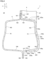
- FIG. 5 is a diagram illustrating a modification of the present invention.
- the position of the rear end edge 228a of the overlapping portion 22 arranged between the center position X0 of the center pillar 4 in the front and rear direction X and the rear restricting position X2 (X2R) is defined as the rear end edge position X1 (X1R).
- the distance from the center position X0 to the rear restricting position X2 (X2R) in the front and rear direction X is defined as L0 (L0R).
- the distance from the center position X0 to the rear end edge position X1R in the front and rear direction X is defined as L1 (L1R).
- L1R/L0R which is the ratio between the distances L0R and L1R
- L1R/L0R is set to 0.36 ⁇ L1R/L0R ⁇ 0.48.
- the lower limit of L1R/L0R may be 0.38, may be 0.40, or may be 0.42. Additionally, the upper limit of L1R/L0R may be 0.46, may be 0.44, or may be 0.42.
- the rear portion 228 of the overlapping portion 22 is arranged so as to be overlapped with the position of a floor cross member 13 in the front and rear direction X.
- the rear portion 228 of the overlapping portion 22 is aligned with the floor cross member 13 in the width direction Y, and thus is overlapped with the position of the floor cross member 13 in the front and rear directions X. It is more preferable that the position of the rear portion 228 of the overlapping portion 22 is overlapped with the entire area of the floor cross member 13 in the front and rear direction X.
- the overlapping portion 22 and the floor cross members 8 and 13 firmly sandwich the side sill 5 at two portions separated in the front and rear direction X, the torsional deformation of the side sill 5 can be more positively suppressed. As a result, the amount of intrusion of the vehicle body 1 toward the cabin 10 at the time of a side collision can be further reduced.
- the front portion 226 may not be arranged so as to be overlapped with the position of the floor cross member 8 in the front and rear direction X.
- the lower end 224b of the overlapping portion 22 may not extend along the bottom surface 154a of the lower wall 154 of the side sill outer 15, and may extend along the upper wall 152, the side wall 153, or the lower flange 155.
- a model of the vehicle body 1 described in the embodiment was created by a computer.
- the specification of the model of the vehicle body 1 is as follows. Thickness of the side sill 5: 1.0 (mm)
- Thickness of the upper portion 21 of the center pillar 4 when the front end edge position X1F and the rear end edge position X1R of the overlapping portion 22 in the front and rear direction X, which will be described later, are of a type 000, it is 2.03 (mm) in the vicinity of a connection portion with the roof pillar 3 (in the vicinity of an upper end portion) and in the vicinity of a connection portion with the overlapping portion 22 (in the vicinity of a lower end portion), and it is 2.45 (mm) in the intermediate portion in the vertical direction Z.
- front end edge position X1F and the rear end edge position X1R of the overlapping portion 22 in the front and rear direction X which will be described later, are of a type other than the type 000, it is 1.45 (mm) in the vicinity of the connection portion with the roof pillar 3 (in the vicinity of the upper end portion) and in the vicinity of the connection portion with the overlapping portion 22 (in the vicinity of the lower end portion), and it is 1.75 (mm) in the intermediate portion in the vertical direction Z.
- Thickness of the overlapping portion 22 of the center pillar 4 when the front end edge position X1F and the rear end edge position X1R of the overlapping portion 22 in the front and rear direction X, which will be described later, are of the type 000, it is 2.03 mm, and in the case of a type other than the type 000, it is 1.45 mm.
- the amount of intrusion (the amount of deformation) of the vehicle body 1 toward the cabin 10 at the time when a side collision occurs to a vehicle body was calculated by computer simulation.
- Side collision conditions were set in conformity with the Euro NCAP (European New Car Assessment Programme). Specifically, the maximum value of the amount of intrusion of the vehicle body 1 toward the cabin 10 at the time when a moving barrier collided with the overlapping portion 22 of the vehicle body 1 at 50 km/h was calculated.
- the calculation locations of the maximum amount of intrusion (mm) were three locations in the vertical direction Z. Specifically, the following measurement height positions 1 to 3 were used. The measurement height positions 1 to 3 are illustrated in Figure 1 .
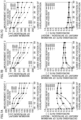
- An upper graph in Figure 7A illustrates the maximum amount of intrusion at the measurement height 1 for each of the lower end positions of the six types of overlapping portions 22, where a horizontal axis represents the type of each lower end position, and a vertical axis represents the value of the maximum amount of intrusion.
- a lower graph in Figure 7A illustrates the decreasing rate of the maximum amount of intrusion / the weight increasing rate at the measurement height 1 for each of the lower end positions of the six types of overlapping portions 22, where a horizontal axis represents the type of each lower end position, and a vertical axis represents the decreasing rate of the maximum amount of intrusion / the weight increasing rate.
- An upper graph in Figure 7B is a graph illustrating the maximum amount of intrusion at the measurement height 2 for each of the lower end positions of the six types of overlapping portions 22.
- a lower graph in Figure 7B is a graph illustrating the decreasing rate of the maximum amount of intrusion / the weight increasing rate at the measurement height 2 for each of the lower end positions of the six types of overlapping portions 22.
- An upper graph in Figure 7C is a graph illustrating the maximum amount of intrusion at the measurement height 3 for each of the lower end positions of the six types of overlapping portions 22.
- a lower graph in Figure 7C is a graph illustrating the decreasing rate of the maximum amount of intrusion / the weight increasing rate at the measurement height 3 for each of the lower end positions of the six types of overlapping portions.
- the decreasing rate of the maximum amount of intrusion refers to the rate of the maximum amount of intrusion in cases in which each lower end position is 10 to 50 to the maximum amount of intrusion in a case in which the lower end position of the overlapping portion 22 is 00.
- the weight increasing rate refers to the rate of the weight of the center pillar 4 in cases in which each lower end position is 10 to 50 to the weight of the center pillar 4 in a case in which the lower end position of the overlapping portion 22 is 00.
- a graph in Figure 8A is a graph illustrating the relationship between the length ratio L1/L0 and the decreasing rate of the maximum amount of intrusion / the weight increasing rate for each of the two types of lower end positions 00 and 30 of the overlapping portion at the measurement height 1.
- a graph in Figure 8B is a graph illustrating the relationship between the length ratio L1/L0 and the decreasing rate of the maximum amount of intrusion / the weight increasing rate for each of the two types of the lower end positions 00 and 30 of the overlapping portion at the measurement height 2.
- a graph in Figure 8C is a graph illustrating the relationship between the length ratio L1/L0 and the decreasing rate of the maximum amount of intrusion / the weight increasing rate for each of the two types of the lower end positions 00 and 30 of the overlapping portion at the measurement height 3.
- the decreasing rate of the maximum amount of intrusion / the weight increasing rate is substantially linearly increased until L1/L0 becomes 0.36. Then, when L1/L0 is more than 0.36, the decreasing rate of the maximum amount of intrusion / the weight increasing rate is substantially linearly decreased. Then, when L1/L0 was more than 0.48, the decreasing rate of the maximum amount of intrusion / the weight increasing rate converged.
- the anti-side collision performance can be increased.
- L1/L0 ⁇ 0.48 an excessive increase in the weight of the overlapping portion 22 can be suppressed. Therefore, it has been proved that, by setting 0.36 ⁇ L1/L0 ⁇ 0.48, the balance between the anti-side collision performance and the suppression of increase in the weight of the center pillar 4 is extremely excellent.
- L1/L0 L1F/L0F
- the side sill 5 and the center pillar 4 have shapes that are generally symmetrical in the front and rear direction. From the above, it is obvious that excellent anti-side collision performance and weight efficiency can be realized by setting 0.36 ⁇ L1/L0 ⁇ 0.48 (0.36 ⁇ L1R/L0R ⁇ 0.48) also for the rear portion 228 of the overlapping portion 22.
- the present invention can be widely applied as a vehicle body structure and a method for designing a vehicle body structure.
Landscapes
- Engineering & Computer Science (AREA)
- Chemical & Material Sciences (AREA)
- Combustion & Propulsion (AREA)
- Transportation (AREA)
- Mechanical Engineering (AREA)
- Body Structure For Vehicles (AREA)
Applications Claiming Priority (3)
| Application Number | Priority Date | Filing Date | Title |
|---|---|---|---|
| JP2022054957 | 2022-03-30 | ||
| JP2022054958 | 2022-03-30 | ||
| PCT/JP2023/006368 WO2023189029A1 (fr) | 2022-03-30 | 2023-02-22 | Structure de carrosserie de véhicule et procédé de conception d'une structure de carrosserie de véhicule |
Publications (2)
| Publication Number | Publication Date |
|---|---|
| EP4501754A1 true EP4501754A1 (fr) | 2025-02-05 |
| EP4501754A4 EP4501754A4 (fr) | 2025-07-23 |
Family
ID=88200494
Family Applications (2)
| Application Number | Title | Priority Date | Filing Date |
|---|---|---|---|
| EP23779059.7A Pending EP4501754A4 (fr) | 2022-03-30 | 2023-02-22 | Structure de carrosserie de véhicule et procédé de conception d'une structure de carrosserie de véhicule |
| EP23779058.9A Pending EP4501753A4 (fr) | 2022-03-30 | 2023-02-22 | Structure de carrosserie de véhicule et procédé de conception de structure de carrosserie de véhicule |
Family Applications After (1)
| Application Number | Title | Priority Date | Filing Date |
|---|---|---|---|
| EP23779058.9A Pending EP4501753A4 (fr) | 2022-03-30 | 2023-02-22 | Structure de carrosserie de véhicule et procédé de conception de structure de carrosserie de véhicule |
Country Status (4)
| Country | Link |
|---|---|
| US (2) | US20250153774A1 (fr) |
| EP (2) | EP4501754A4 (fr) |
| JP (2) | JP7751236B2 (fr) |
| WO (2) | WO2023189028A1 (fr) |
Families Citing this family (2)
| Publication number | Priority date | Publication date | Assignee | Title |
|---|---|---|---|---|
| KR20240018949A (ko) * | 2022-08-03 | 2024-02-14 | 현대자동차주식회사 | 차량의 측면 보강 구조 |
| WO2025084325A1 (fr) * | 2023-10-18 | 2025-04-24 | 日本製鉄株式会社 | Élément d'absorption d'impact et carrosserie de véhicule |
Family Cites Families (15)
| Publication number | Priority date | Publication date | Assignee | Title |
|---|---|---|---|---|
| JP3385079B2 (ja) * | 1993-10-22 | 2003-03-10 | マツダ株式会社 | 溶接成形品の製造方法 |
| JPH09295160A (ja) * | 1996-05-10 | 1997-11-18 | Sumitomo Metal Ind Ltd | 接合構造部材およびその製造方法 |
| JP4120052B2 (ja) * | 1998-08-03 | 2008-07-16 | 住友金属工業株式会社 | 衝突エネルギー吸収性に優れた鋼構造部材 |
| JP2001294178A (ja) | 2000-04-17 | 2001-10-23 | Suzuki Motor Corp | 車体側部の構造 |
| JP3903803B2 (ja) | 2002-01-28 | 2007-04-11 | 日産自動車株式会社 | 車体結合構造 |
| JP2003306165A (ja) * | 2002-04-16 | 2003-10-28 | Mitsubishi Motors Corp | 車体の側部構造体 |
| JP4272626B2 (ja) * | 2005-01-20 | 2009-06-03 | 本田技研工業株式会社 | 車体下側部構造 |
| JP5330668B2 (ja) | 2007-10-22 | 2013-10-30 | トヨタ自動車株式会社 | 車両のピラー構造 |
| DE102009057734A1 (de) * | 2009-12-10 | 2011-06-16 | Daimler Ag | Verfahren zum Herstellen eines Rohbaus eines Kraftwagens sowie Rohbau für einen Kraftwagen |
| JP5531835B2 (ja) | 2010-07-12 | 2014-06-25 | Jfeスチール株式会社 | 軽量化に適した車体側部構造 |
| JP6256310B2 (ja) | 2014-11-13 | 2018-01-10 | トヨタ自動車株式会社 | 車両側部構造 |
| JP6292173B2 (ja) * | 2015-04-01 | 2018-03-14 | Jfeスチール株式会社 | 車両用センターピラー構造の決定方法 |
| JP7207108B2 (ja) * | 2019-04-03 | 2023-01-18 | トヨタ自動車株式会社 | 車体側部構造 |
| CN211032749U (zh) * | 2019-09-19 | 2020-07-17 | 海马新能源汽车有限公司 | 汽车侧围骨架、车身及汽车 |
| JP7186893B2 (ja) * | 2019-10-04 | 2022-12-09 | 本田技研工業株式会社 | 車体側部構造 |
-
2023
- 2023-02-22 EP EP23779059.7A patent/EP4501754A4/fr active Pending
- 2023-02-22 EP EP23779058.9A patent/EP4501753A4/fr active Pending
- 2023-02-22 US US18/836,089 patent/US20250153774A1/en active Pending
- 2023-02-22 WO PCT/JP2023/006367 patent/WO2023189028A1/fr not_active Ceased
- 2023-02-22 JP JP2024511450A patent/JP7751236B2/ja active Active
- 2023-02-22 WO PCT/JP2023/006368 patent/WO2023189029A1/fr not_active Ceased
- 2023-02-22 JP JP2024511449A patent/JP7751235B2/ja active Active
- 2023-02-22 US US18/836,108 patent/US20250128767A1/en active Pending
Also Published As
| Publication number | Publication date |
|---|---|
| US20250153774A1 (en) | 2025-05-15 |
| EP4501754A4 (fr) | 2025-07-23 |
| US20250128767A1 (en) | 2025-04-24 |
| JPWO2023189029A1 (fr) | 2023-10-05 |
| JP7751235B2 (ja) | 2025-10-08 |
| WO2023189028A1 (fr) | 2023-10-05 |
| JPWO2023189028A1 (fr) | 2023-10-05 |
| EP4501753A1 (fr) | 2025-02-05 |
| WO2023189029A1 (fr) | 2023-10-05 |
| JP7751236B2 (ja) | 2025-10-08 |
| EP4501753A4 (fr) | 2025-07-23 |
Similar Documents
| Publication | Publication Date | Title |
|---|---|---|
| US7699385B2 (en) | Vehicle body structure | |
| CN105438273B (zh) | 汽车的机盖结构 | |
| CN114340980B (zh) | 用于电动车辆的前部结构 | |
| US8960780B2 (en) | Vehicle side body structure | |
| EP1943137B1 (fr) | Structure inferieure de carrosserie de vehicule | |
| US11400984B2 (en) | Vehicle body side part structure | |
| CN112660244B (zh) | 一种偏置碰防撞车体结构 | |
| EP4501754A1 (fr) | Structure de carrosserie de véhicule et procédé de conception d'une structure de carrosserie de véhicule | |
| CN108495777A (zh) | 车辆前部构造 | |
| EP4253114A1 (fr) | Boîtier de batterie automobile et son procédé de fabrication | |
| CN113291381A (zh) | 一种汽车b柱加强结构及汽车b柱 | |
| CN109591892B (zh) | 车辆的车身侧部的上部拱形构造 | |
| EP3932750B1 (fr) | Élément structural pour véhicule | |
| CN212500670U (zh) | 车身结构及汽车 | |
| CN105730513A (zh) | 车身a立柱上铰链加强结构 | |
| EP3875351B1 (fr) | Élément et cadre de véhicule | |
| US9580029B2 (en) | Bumper assemblies including a bumper cover reinforcement and vehicles incorporating the same | |
| CN113968281A (zh) | 车身结构及汽车 | |
| US11993317B2 (en) | Vehicle center pillar structure | |
| US12409896B2 (en) | Lower vehicle-body structure of vehicle | |
| CN118786067A (zh) | 车身构造和车身构造的设计方法 | |
| JP7491962B2 (ja) | 車両の補強構造 | |
| KR20250153252A (ko) | 자동차의 서브프레임 구조 | |
| WO2025173741A1 (fr) | Structure de châssis de véhicule automobile | |
| EP4653296A1 (fr) | Structure de squelette pour un véhicule |
Legal Events
| Date | Code | Title | Description |
|---|---|---|---|
| STAA | Information on the status of an ep patent application or granted ep patent |
Free format text: STATUS: THE INTERNATIONAL PUBLICATION HAS BEEN MADE |
|
| PUAI | Public reference made under article 153(3) epc to a published international application that has entered the european phase |
Free format text: ORIGINAL CODE: 0009012 |
|
| STAA | Information on the status of an ep patent application or granted ep patent |
Free format text: STATUS: REQUEST FOR EXAMINATION WAS MADE |
|
| 17P | Request for examination filed |
Effective date: 20241030 |
|
| AK | Designated contracting states |
Kind code of ref document: A1 Designated state(s): AL AT BE BG CH CY CZ DE DK EE ES FI FR GB GR HR HU IE IS IT LI LT LU LV MC ME MK MT NL NO PL PT RO RS SE SI SK SM TR |
|
| DAV | Request for validation of the european patent (deleted) | ||
| DAX | Request for extension of the european patent (deleted) | ||
| A4 | Supplementary search report drawn up and despatched |
Effective date: 20250624 |
|
| RIC1 | Information provided on ipc code assigned before grant |
Ipc: B62D 25/04 20060101AFI20250617BHEP Ipc: B62D 25/20 20060101ALI20250617BHEP Ipc: B62D 21/15 20060101ALI20250617BHEP Ipc: B62D 25/02 20060101ALI20250617BHEP Ipc: B62D 27/02 20060101ALI20250617BHEP |