EP4501779A1 - Système de montage de radôme - Google Patents
Système de montage de radôme Download PDFInfo
- Publication number
- EP4501779A1 EP4501779A1 EP24190107.3A EP24190107A EP4501779A1 EP 4501779 A1 EP4501779 A1 EP 4501779A1 EP 24190107 A EP24190107 A EP 24190107A EP 4501779 A1 EP4501779 A1 EP 4501779A1
- Authority
- EP
- European Patent Office
- Prior art keywords
- adapter plate
- anchors
- spinwheel
- mounting system
- vertically adjustable
- Prior art date
- Legal status (The legal status is an assumption and is not a legal conclusion. Google has not performed a legal analysis and makes no representation as to the accuracy of the status listed.)
- Pending
Links
Images




Classifications
-
- B—PERFORMING OPERATIONS; TRANSPORTING
- B64—AIRCRAFT; AVIATION; COSMONAUTICS
- B64C—AEROPLANES; HELICOPTERS
- B64C1/00—Fuselages; Constructional features common to fuselages, wings, stabilising surfaces or the like
- B64C1/36—Fuselages; Constructional features common to fuselages, wings, stabilising surfaces or the like adapted to receive antennas or radomes
-
- H—ELECTRICITY
- H01—ELECTRIC ELEMENTS
- H01Q—ANTENNAS, i.e. RADIO AERIALS
- H01Q1/00—Details of, or arrangements associated with, antennas
- H01Q1/12—Supports; Mounting means
-
- H—ELECTRICITY
- H01—ELECTRIC ELEMENTS
- H01Q—ANTENNAS, i.e. RADIO AERIALS
- H01Q1/00—Details of, or arrangements associated with, antennas
- H01Q1/27—Adaptation for use in or on movable bodies
- H01Q1/28—Adaptation for use in or on aircraft, missiles, satellites, or balloons
- H01Q1/286—Adaptation for use in or on aircraft, missiles, satellites, or balloons substantially flush mounted with the skin of the craft
-
- H—ELECTRICITY
- H01—ELECTRIC ELEMENTS
- H01Q—ANTENNAS, i.e. RADIO AERIALS
- H01Q1/00—Details of, or arrangements associated with, antennas
- H01Q1/42—Housings not intimately mechanically associated with radiating elements, e.g. radome
Definitions
- This invention relates generally to a mounting system for external aircraft electronics and/or hardware, such as a radome.
- a radome and other components are often affixed to an outer skin of an aircraft fuselage. Given the precise tolerance required as well as the confined space available within and surrounding a radome, installation has been problematic and often difficult to duplicate. Traditional installations require trial and error in order to attach the radome in a secure manner on a variety of fuselage geometries.
- One such installation technique requires anchoring and shimming connection points around an adapter plate until the adapter plate is free of movement and vibration relative to the fuselage.
- the invention generally relates to a mounting system and aircraft radome for electronics and/or hardware such as antennae, communications systems, etc.
- a preferred mounting system includes one or more fixed anchors and a plurality of vertically adjustable anchors each attached to an aircraft fuselage.
- An adapter plate is preferably affixed to the anchors such that the fixed anchors are centrally located along outer edges of the adapter plate and the vertically adjustable anchors are positioned at ends of the adapter plate.
- Each vertically adjustable anchor preferably includes a spinwheel on a threaded shaft.
- the adapter plate is attached to the fixed anchors and the adjustable anchors so that a contact surface of the spinwheel directly engages with the adapter plate.
- the subject mounting system may further include a plurality of fasteners attached between the fixed anchors and the adapter plate. Likewise, a plurality of fasteners may be attached between each spinwheel of the vertically adjustable anchors the adapter plate.
- each of the plurality of fasteners are accessible from a top of the adapter plate. Such an arrangement facilitates assembly and modification of the mounting system.
- the adapter plate is preferably fitted with electronics and hardware including antennae and/or other communication and navigation equipment within the radome and a domed cover.
- a skirt may be attached to a lower edge of the adapter plate to bridge the lower edge of the adapter plate to the fuselage.
- the present invention provides a mounting system for electronics and/or hardware such as a radome, antennae, etc. for an aircraft fuselage 10.
- a preferred mounting system includes one or more fixed anchors 20 attached to the fuselage 10.
- a plurality of vertically adjustable anchors 30 are attached to the fuselage 10.
- An adapter plate 40 is then affixed to the anchors 20, 30, as described in more detail below.
- the anchors 20, 30 may be attached to the fuselage 10 using shoulder bolts and may include pivoting bases to accommodate the adapter plate 40.
- the fixed anchors 20 are interspersed with the vertically adjustable anchors 30.
- the fixed anchors 20 may be dispersed along outer edges of the adapter plate 40 and the vertically adjustable anchors 30 are positioned between those fixed anchors 20 along the adapter plate 40. More particularly, an arrangement of a single aft fixed anchor 20, two mid-aft vertically adjustable anchors 30, two central fixed anchors 20, and two forward vertically adjustable anchors 30 are shown in Figs. 1 and 8 .
- Each vertically adjustable anchor 30 preferably includes a spinwheel 50 on a threaded shaft 60.
- the spinwheel 50 is preferably aluminum or steel and may include a threaded core or a helical insert, such as a HELICOIL to engage the threaded shaft 60.
- the spinwheel 50 may be fixed into position with a locking plate 65 which may be additionally affixed with fasteners as shown.
- an adapter plate 40 is attached to the fixed anchors 20 and the adjustable anchors 30, wherein a contact surface of the spinwheel 50 directly engages with the adapter plate 40.
- the adapter plate 40 is thus configured to accommodate aircraft electronics within the radome include antennae and related communications and guidance systems.
- the adapter plate 40 may be a single piece or a multi-piece assembly.
- the adapter plate 40 may further include bosses for antenna mounting and/or channels 70 for engagement with anchors 20, 30.
- the adapter plate 40 includes a channel 70 to accommodate an outer diameter of the spinwheel 50.
- the contact surface of the spinwheel 50 preferably engages with a connection surface 75 of the adapter plate 40 within the channel 70.
- the subject mounting system may further include a plurality of fasteners 25 attached between the fixed anchors 20 and the adapter plate 40.
- the fasteners may comprise nuts and bolts, rivets or other appropriate connectors for maintaining the two components into a fixed position with each other.
- the subject mounting system may further include a plurality of fasteners 55 attached between each spinwheel 50 of the vertically adjustable anchors 30 the adapter plate 40.
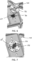
- the spinwheel 50 may be configured to engage upwardly on the adapter plate 40 in some areas (as shown in Figs. 4 and 5 ) and downwardly in other areas (as shown in Fig. 6 and 7 ).
- Fig. 5 shows the additional placement of a locking plate 65 to maintain a desired position of the spinwheel 50.
- the threaded shaft 60 may include a square or similar polygonal head that engages with a corresponding aperture in the locking plate 65.
- the locking plate 50 may be affixed with one or more fasteners to the spinwheel 50.
- a pair of rearward vertically adjustable anchors 30 may be connected to engage the adapter plate 40 in an upwardly biased connection and a pair of forward vertically adjustable anchors 30 may be connected to engage the adapter plate in a downwardly biased connection.
- these anchors 20, 30 and a preferred arrangement maintains a tight-fitting and immovable connection between the adapter plate 40 and the fuselage 10. This is critical given the forces exerted on the radome 100 during operation and maintenance of the aircraft - any small tolerance or movement may become much greater during operation.
- each of the plurality of fasteners 25, 55 are accessible from a top of the adapter plate 40. Such an arrangement facilitates assembly and modification of the mounting system.
- the adapter plate 40 is preferably fitted with electronics and hardware including antennae and/or other communication and navigation equipment within the radome and a domed cover.
- a skirt 80 may be attached to a lower edge of the adapter plate 40, the skirt 80 bridging the lower edge of the adapter plate 40 to the fuselage 10.
- the skirt 80 preferably enhances aerodynamics and helps protect the hardware and electronics within the radome.
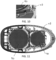
- the radome extends approximately 6-12 inches over the fuselage 10 and the skirt 80 preferably extends downward from the adapter plate 40 into flush contact with the fuselage 10, such as shown in Figs. 12 and 13 .
- a related method for mounting hardware and/or electronics to an aircraft fuselage using the apparatus described above may include attaching two or more fixed anchors 20 to the fuselage 10 using fasteners 25 as described above.
- a plurality of vertically adjustable anchors 30 may be attached to the fuselage, wherein each vertically adjustable anchor includes a spinwheel 50 on a threaded shaft.
- the adapter plate 40 is preferably directly engaged with the vertically adjustable anchors 30 wherein a contact surface of the spinwheel 50 directly engages with the adapter plate 40.
- the respective spinwheels 50 are fastened to the adapter plate 40 each with a plurality of fasteners 55.
- the adapter plate 40 is first attached to the fixed anchors 20 and then the adjustable anchors 30. In this manner, at least two fixed points along the adapter plate 40 are established and then the spinwheels 50 are rotated into direct contact with the underside of the adapter plate 40 and, separately, the topside of the adapter plate 40 before fastening the respective spinwheels 50 to the adapter plate 40.
- ground straps 110 may be then attached to each of the antennae 90, the fixed anchors 20 and the adjustable anchors 30, preferably using pre-installed ground screws at each anchor point.
Landscapes
- Engineering & Computer Science (AREA)
- Aviation & Aerospace Engineering (AREA)
- Physics & Mathematics (AREA)
- Astronomy & Astrophysics (AREA)
- General Physics & Mathematics (AREA)
- Remote Sensing (AREA)
- Mechanical Engineering (AREA)
- Details Of Aerials (AREA)
Applications Claiming Priority (1)
| Application Number | Priority Date | Filing Date | Title |
|---|---|---|---|
| US18/228,232 US12374784B2 (en) | 2022-08-02 | 2023-07-31 | Radome mounting system |
Publications (1)
| Publication Number | Publication Date |
|---|---|
| EP4501779A1 true EP4501779A1 (fr) | 2025-02-05 |
Family
ID=91961584
Family Applications (1)
| Application Number | Title | Priority Date | Filing Date |
|---|---|---|---|
| EP24190107.3A Pending EP4501779A1 (fr) | 2023-07-31 | 2024-07-22 | Système de montage de radôme |
Country Status (1)
| Country | Link |
|---|---|
| EP (1) | EP4501779A1 (fr) |
Citations (3)
| Publication number | Priority date | Publication date | Assignee | Title |
|---|---|---|---|---|
| US7677498B2 (en) * | 2004-06-29 | 2010-03-16 | Airbus France | Device and method for fastening an aircraft radome |
| EP3239038A1 (fr) * | 2016-04-29 | 2017-11-01 | Embraer S.A. | Ensembles de connexion rapide, particulièrement utiles pour coupler des carénages d'antenne d'aéronef à des structures cellulaires |
| US10640193B2 (en) * | 2017-07-21 | 2020-05-05 | Carlisle Interconnect Technologies, Inc. | Mounting systems for mounting an element to a surface |
-
2024
- 2024-07-22 EP EP24190107.3A patent/EP4501779A1/fr active Pending
Patent Citations (3)
| Publication number | Priority date | Publication date | Assignee | Title |
|---|---|---|---|---|
| US7677498B2 (en) * | 2004-06-29 | 2010-03-16 | Airbus France | Device and method for fastening an aircraft radome |
| EP3239038A1 (fr) * | 2016-04-29 | 2017-11-01 | Embraer S.A. | Ensembles de connexion rapide, particulièrement utiles pour coupler des carénages d'antenne d'aéronef à des structures cellulaires |
| US10640193B2 (en) * | 2017-07-21 | 2020-05-05 | Carlisle Interconnect Technologies, Inc. | Mounting systems for mounting an element to a surface |
Similar Documents
| Publication | Publication Date | Title |
|---|---|---|
| EP1723033B1 (fr) | Dispositif et procede de fixation pour un office a bord | |
| US20180016008A1 (en) | Aircraft Monument Floor Mounting System | |
| US20200278077A1 (en) | Metal roof mounting brackets | |
| EP4005931A1 (fr) | Écrou d'ancrage pour un système de capuchon de protection eme | |
| EP3656016B1 (fr) | Systèmes de montage pour le montage d'un élément sur une surface d'aéronef | |
| JP2013504468A (ja) | レドーム及びそのレドームを航空機に取付けるための装置 | |
| EP4501779A1 (fr) | Système de montage de radôme | |
| US12374784B2 (en) | Radome mounting system | |
| US20060251496A1 (en) | Fastener arrangement for fastening a detachable panel | |
| US5456442A (en) | Mounting bracket for global positioning system antenna | |
| US7784734B2 (en) | Apparatus and method for rigging slaved and actuated panels with external access | |
| US7677498B2 (en) | Device and method for fastening an aircraft radome | |
| US9694909B2 (en) | Modular mounting structure with embedded electrical bus | |
| US11679861B2 (en) | Assembly for an aircraft, the assembly having a pylon and a wing | |
| EP2690014B1 (fr) | Dispositif d'étanchéité pour point de montage de cuisine de bord | |
| US20070023573A1 (en) | Aircraft wing | |
| US11472574B2 (en) | Methods and assemblies for mounting equipment to an aircraft | |
| KR20210143655A (ko) | 홀을 형성하도록 천공 비트를 안내하기 위한 장치들 및 방법들 | |
| ATE241748T1 (de) | Selbstausrichtendes befestigungssystem | |
| US20250226646A1 (en) | Adjustable spacing device | |
| US11364988B2 (en) | Multi-purpose shoulder panel system | |
| US9994298B2 (en) | System for embedded removable aperture | |
| EP3800130B1 (fr) | Échafaudage interne suspendu d'aéronef | |
| RU229490U1 (ru) | Носовой отсек фюзеляжа вертолета для размещения блока аппаратуры | |
| US11708173B2 (en) | Avionic sliding rack |
Legal Events
| Date | Code | Title | Description |
|---|---|---|---|
| PUAI | Public reference made under article 153(3) epc to a published international application that has entered the european phase |
Free format text: ORIGINAL CODE: 0009012 |
|
| STAA | Information on the status of an ep patent application or granted ep patent |
Free format text: STATUS: THE APPLICATION HAS BEEN PUBLISHED |
|
| AK | Designated contracting states |
Kind code of ref document: A1 Designated state(s): AL AT BE BG CH CY CZ DE DK EE ES FI FR GB GR HR HU IE IS IT LI LT LU LV MC ME MK MT NL NO PL PT RO RS SE SI SK SM TR |
|
| STAA | Information on the status of an ep patent application or granted ep patent |
Free format text: STATUS: REQUEST FOR EXAMINATION WAS MADE |
|
| 17P | Request for examination filed |
Effective date: 20250710 |
|
| STAA | Information on the status of an ep patent application or granted ep patent |
Free format text: STATUS: EXAMINATION IS IN PROGRESS |
|
| 17Q | First examination report despatched |
Effective date: 20260313 |