EP4501793A1 - Flugzeuglufteinlass mit einer aussenwand und vorder- und hinterrahmen, die durch mindestens ein separates verbindungselement der aussenwand verbunden sind - Google Patents
Flugzeuglufteinlass mit einer aussenwand und vorder- und hinterrahmen, die durch mindestens ein separates verbindungselement der aussenwand verbunden sind Download PDFInfo
- Publication number
- EP4501793A1 EP4501793A1 EP24188740.5A EP24188740A EP4501793A1 EP 4501793 A1 EP4501793 A1 EP 4501793A1 EP 24188740 A EP24188740 A EP 24188740A EP 4501793 A1 EP4501793 A1 EP 4501793A1
- Authority
- EP
- European Patent Office
- Prior art keywords
- edge
- lip
- air inlet
- frame
- outer edge
- Prior art date
- Legal status (The legal status is an assumption and is not a legal conclusion. Google has not performed a legal analysis and makes no representation as to the accuracy of the status listed.)
- Pending
Links
Images


Classifications
-
- B—PERFORMING OPERATIONS; TRANSPORTING
- B64—AIRCRAFT; AVIATION; COSMONAUTICS
- B64D—EQUIPMENT FOR FITTING IN OR TO AIRCRAFT; FLIGHT SUITS; PARACHUTES; ARRANGEMENT OR MOUNTING OF POWER PLANTS OR PROPULSION TRANSMISSIONS IN AIRCRAFT
- B64D33/00—Arrangement in aircraft of power plant parts or auxiliaries not otherwise provided for
- B64D33/02—Arrangement in aircraft of power plant parts or auxiliaries not otherwise provided for of combustion air intakes
-
- B—PERFORMING OPERATIONS; TRANSPORTING
- B64—AIRCRAFT; AVIATION; COSMONAUTICS
- B64D—EQUIPMENT FOR FITTING IN OR TO AIRCRAFT; FLIGHT SUITS; PARACHUTES; ARRANGEMENT OR MOUNTING OF POWER PLANTS OR PROPULSION TRANSMISSIONS IN AIRCRAFT
- B64D29/00—Power-plant nacelles, fairings or cowlings
- B64D29/06—Attaching of nacelles, fairings or cowlings
-
- F—MECHANICAL ENGINEERING; LIGHTING; HEATING; WEAPONS; BLASTING
- F02—COMBUSTION ENGINES; HOT-GAS OR COMBUSTION-PRODUCT ENGINE PLANTS
- F02C—GAS-TURBINE PLANTS; AIR INTAKES FOR JET-PROPULSION PLANTS; CONTROLLING FUEL SUPPLY IN AIR-BREATHING JET-PROPULSION PLANTS
- F02C7/00—Features, components parts, details or accessories, not provided for in, or of interest apart form groups F02C1/00 - F02C6/00; Air intakes for jet-propulsion plants
- F02C7/04—Air intakes for gas-turbine plants or jet-propulsion plants
-
- B—PERFORMING OPERATIONS; TRANSPORTING
- B64—AIRCRAFT; AVIATION; COSMONAUTICS
- B64D—EQUIPMENT FOR FITTING IN OR TO AIRCRAFT; FLIGHT SUITS; PARACHUTES; ARRANGEMENT OR MOUNTING OF POWER PLANTS OR PROPULSION TRANSMISSIONS IN AIRCRAFT
- B64D33/00—Arrangement in aircraft of power plant parts or auxiliaries not otherwise provided for
- B64D33/02—Arrangement in aircraft of power plant parts or auxiliaries not otherwise provided for of combustion air intakes
- B64D2033/0206—Arrangement in aircraft of power plant parts or auxiliaries not otherwise provided for of combustion air intakes comprising noise reduction means, e.g. acoustic liners
Definitions
- the present application relates to an aircraft air intake comprising an outer wall and front and rear frames connected by at least one connecting element distinct from the outer wall as well as to an aircraft comprising at least one propulsion assembly which comprises such an air intake.
- an aircraft 10 comprises several propulsion units 12 each comprising a motorization 14 as well as a nacelle 16 surrounding the motorization 14 and in particular making it possible to channel an air flow towards the motorization 14.
- the motorization 14 has an axis of rotation A14.
- a longitudinal direction is a direction parallel to the axis of rotation A14.
- a longitudinal plane is a plane containing the axis of rotation A14.
- a transverse plane is a plane perpendicular to the axis of rotation A14.
- each nacelle 16 comprises, at the front, an air inlet 18 configured to separate a laminar air flow 20 into a laminar interior air flow 20.1 which enters the nacelle 16 in the direction of the motorization 14 and a laminar exterior air flow 20.2 flowing outside the nacelle 16.
- the front frame 28 and the lip 22 delimit an annular D-shaped duct 32, called a D-duct.
- the front and rear frames 28, 30 are positioned approximately in two transverse planes.
- the front frame may be slightly frustoconical and form an angle of the order of 10° with a transverse plane.
- the interior panel 26 is equipped with an acoustic attenuation structure.
- the peripheral outer edge 28.1 of the front frame 28 has a rim 34 pressed against the outer portion 24.2 of the lip 22 and connected to the latter by a series of connecting elements 36 distributed over the entire circumference of the nacelle.
- the outer rear edge of the lip 22 is connected to the front frame 28 by a first series of connecting elements.
- the air inlet comprises an outer panel positioned in the extension of the outer portion 24.2 of the lip 22 which has a front edge connected to the front frame as well as a rear edge connected to the rear frame.
- the air inlet 18 comprises at least one series of connecting elements, positioned in line with the front frame 28, which are flush with a wall of the air inlet (the lip 22 and/or an exterior panel) in contact with the exterior air flow 20.2.
- the external air flow 20.2 is laminar from the leading edge 24.1 (also called the aerodynamic stopping point) over a certain length which must be as long as possible to reduce the drag generated by the air inlet 18 of the nacelle 16.
- leading edge 24.1 also called the aerodynamic stopping point
- the theoretical length, characterizing the laminar air zone could reach a distance of the order of 400 to 950 mm depending on the size of the nacelle.
- the air intake 18 comprises connecting elements 36 spaced from the leading edge 24.1 by a distance of less than 500 mm, of the order of 300 mm, which generate disturbances, which results in an increase in the drag of the air intake 18 of the nacelle 16 and, ultimately, in the energy consumption of the aircraft 10.
- the air intake comprises at least one connecting element connecting the front and rear peripheral outer edges of the front frame and the rear frame, the front peripheral outer edge being spaced from the lip.
- each connecting element has a front end
- the air intake comprising a front connecting system connecting the front end of each connecting element and the front peripheral outer edge of the front frame, the front peripheral outer edge of the front frame being curved so as to have a substantially cylindrical shape
- the front connecting system comprising at least one series of connecting elements, distributed over at least one circle, crossing the front peripheral outer edge of the front frame and the front end of each connecting element.
- the air intake Since the front frame is not connected to the lip, the air intake has no connecting element, at the level of the front frame, flush with the outer face of the lip. Thus, the air flow which flows in contact with the air intake retains its laminar character over the greatest possible length.
- the air inlet comprises a single tubular junction element, substantially coaxial with the interior panel.
- the air inlet comprises several spaced-apart connecting elements distributed around the interior panel.
- each connecting element has a rear end, the air inlet comprising a rear connecting system which connects the rear end of each connecting element and the rear peripheral outer edge of the rear frame.
- each connecting element is curved and pressed against the rear peripheral outer edge of the rear frame.
- the rear connecting system comprises at least one series of connecting elements, distributed over at least one circle, crossing the rear end of each connecting element and the rear peripheral outer edge of the rear frame.
- the lip and each joining element are connected by a connecting system located near the outer rear edge of the lip.
- each joining element has a rib, at the level of the connecting system, configured to space the lip and each joining element outside the rib.
- the rib has a substantially cylindrical central portion, further spaced from the inner panel than the rest of the joining element, as well as two truncated cone-shaped portions connecting the central portion to the rest of the joining element.
- the invention also relates to an aircraft comprising at least one propulsion assembly which comprises an air inlet according to one of the preceding characteristics.
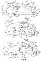
- an aircraft comprises at least one propulsion assembly which comprises an air inlet 40 for channeling an air flow 42 towards a motorization.
- the other elements of the propulsion assembly are not shown in the Figures 4 to 8 . They are known to those skilled in the art and may be identical to those of the prior art.
- the air inlet 40 has a longitudinal axis coincident with the axis of the motorization when the air inlet 40 is connected to the motorization.
- the air inlet 40 comprises a lip 44 which has a C-shape in section in a longitudinal plane.
- the lip 44 comprises a leading edge 46.1 which splits the air flow 42 into an inner air flow 42.1 and an outer air flow 42.2, an outer portion 46.2 which extends from the leading edge 46.1 to an outer rear edge 44.1 of the lip 44 and over which the outer air flow 42.2 flows and an inner portion 46.3 which extends from the leading edge 46.1 to an inner rear edge 44.2 of the lip 44 and over which the inner air flow 42.1 flows.
- the lip 44 has an outer face F44 in contact with the interior and exterior air flows 42.1, 42.2 as well as an interior face F44'
- the front and rear frames 50, 52 are positioned approximately in two transverse planes.
- the front or rear frame may be slightly frustoconical and form an angle of the order of 10° with a transverse plane.
- the interior panel 48 is equipped with an acoustic attenuation structure.
- the air inlet 40 comprises a first connecting system 54 connecting the front edge 48.1 of the inner panel 48 and the inner rear edge 44.2 of the lip 44.
- the front edge 48.1 of the inner panel 48 is pressed against the inner face F44' of the lip 44 at the inner rear edge 44.2 of the lip 44.
- the first connecting system 54 comprises a series of connecting elements 54.1, distributed over at least one circle around the longitudinal axis of the air inlet 40, passing through the parts of the lip 44 and the inner panel 48 which overlap.
- the first connecting system 54 makes it possible to connect the front edge 48.1 of the inner panel 48, the inner rear edge 44.2 of the lip 44 and the front peripheral inner edge 50.2 of the front frame 50.
- the front peripheral inner edge 50.2 of the front frame 50 is curved and pressed against the front edge 48.1 of the inner panel 48.
- the first connecting system 54 comprises a series of connecting elements 54.1, distributed over at least one circle around the axis longitudinal of the air inlet 40, passing through the portions of the lip 44, the inner panel 48 and the front frame 50 which overlap.
- the air inlet 40 comprises, in addition to the first connecting system 54, a second connecting system 56 connecting the front peripheral inner edge 50.2 of the front frame 50 and the inner panel 48.
- the front peripheral inner edge 50.2 of the front frame 50 is curved and pressed against the inner panel 48 in an area spaced from the front edge 48.1 of the inner panel 48.
- the second connecting system 56 comprises a series of connecting elements 56.1, distributed over at least one circle around the longitudinal axis of the air inlet 40, crossing the front peripheral inner edge 50.2 of the front frame 50 and being housed in the inner panel 48.
- the invention is not limited to these embodiments.
- the front peripheral inner edge 50.2 of the front frame 50 could be curved, pressed against the lip 44 and connected to the latter in an area spaced from the inner panel 48.
- the air inlet 40 also comprises a third connecting system 58 connecting the rear peripheral inner edge 52.2 of the rear frame 52 and the rear edge 48.2 of the interior panel 48.
- the rear peripheral inner edge 52.2 of the rear frame 52 is curved, pressed against the rear edge 48.2 of the interior panel 48 (or against an element connected to the interior panel 48) and connected to the latter.
- the third connecting system 58 comprises a series of connecting elements 58.1, distributed over at least one circle around the longitudinal axis of the air intake 40, crossing the rear peripheral inner edge 52.2 of the rear frame 52 and housed in the inner panel 48.
- the air intake 40 comprises a rear connection system 60 configured to connect the air intake 40 to the engine of the propulsion assembly, more particularly to a fan casing of the engine.
- this rear connection system 60 comprises at least one angle iron which has a first wing 60.1 connected to the inner panel 48 as well as a second wing 60.2 positioned in a transverse plane and intended to be connected to the fan casing.
- the rear peripheral inner edge 52.2 of the rear frame 52 is curved, pressed against the first wing 60.1 of the rear connection system 60 itself pressed against the interior panel 48, the connecting elements 58.1 crossing the edge rear peripheral interior 52.2 of the rear frame 52, the first wing 60.1 and housed in the interior panel 48.
- the invention is not limited to this embodiment for connecting the interior panel 48, the rear frame 52 and/or the rear connection system 60.
- the air inlet 40 comprises a connecting system 62 directly or indirectly connecting the rear peripheral outer edge 52.1 of the rear frame 52 and the rear outer edge 44.1 of the lip 44.
- the air inlet 40 comprises at least one joining element 64 connecting the front and rear peripheral outer edges 50.1, 52.1 of the front frame 50 and the rear frame 52.
- the air inlet 40 comprises a single tubular connecting element 64, substantially coaxial with the inner panel 48, which extends over the entire circumference of the air inlet 40.
- the connecting element 64 comprises several parts connected together so as to form a single piece.
- the air inlet 40 comprises several spaced-apart connecting elements 64, distributed around the interior panel 48.
- each connecting element 64 has a front end 64.1 connected to the front frame 50 and a rear end 64.2 connected to the rear frame 52.
- the air inlet 40 comprises a front connecting system 66 connecting the front end 64.1 of each connecting element 64 and the front peripheral outer edge 50.1 of the front frame 50 and a rear connecting system 68 connecting the rear end 64.2 of each connecting element 64 and the rear peripheral outer edge 52.1 of the rear frame 52.
- the front peripheral outer edge 50.1 of the front frame 50 is curved so as to have a substantially cylindrical shape, coaxial with the front end 64.1 of the connecting element 64, covering the latter.
- the front connecting system 66 comprises at least one series of connecting elements 66.1, distributed over at least one circle around the longitudinal axis of the air inlet 40, passing through the front peripheral outer edge 50.1 of the front frame 50 and the front end 64.1 of each connecting element 64.
- the invention is not limited to this embodiment for the connection between the front frame 50 and each connecting element 64.
- each connecting element 64 is curved, pressed against the rear peripheral outer edge 52.1 of the rear frame 52.
- the rear connecting system 68 comprises at least one series of connecting elements 68.1, distributed over at least one circle around the longitudinal axis of the air intake 40, passing through the rear end 64.2 of each connecting element 64 and the rear peripheral outer edge 52.1 of the rear frame 52.
- the invention is not limited to this embodiment for the connection between the rear frame 52 and each connecting element 64.
- the lip 44 is connected to each connecting element 64 by a connecting system 70, located near the rear outer edge 44.1 of the lip 44, comprising at least one series of connecting elements 70.1, distributed over at least one circle around the longitudinal axis of the air intake 40, passing through the rear end 64.2 of each connecting element 64 and the rear peripheral outer edge 52.1 of the rear frame 52. less than one circle around the longitudinal axis of the air inlet 40, passing through the lip 44 and each junction element 64.
- the joining element 64 is positioned between the lip 44 and the interior panel 48.
- Each joining element 64 has, at the level of the connecting system 70, a rib 72 configured to space the lip 44 and each joining element 64 outside the rib 72.
- the rib(s) 72 is (or are) positioned in a transverse plane.
- the rib 72 has an omega-shaped section in planes passing through the longitudinal axis of the air inlet 40.
- the rib 72 has a substantially cylindrical central portion 72.1, further spaced from the inner panel 48 than the remainder of the joining element 64, as well as two frustoconical portions 72.2, 72.3 connecting the central portion 72.1 to the remainder of the joining element 64.
- the invention is not limited to this omega shape for the rib 72. Since the joining element 64 is spaced from the lip 44 outside the rib 72, the latter is configured to press at least one area of the joining element 64 against the inner face F44' of the lip 44 to connect it to the lip by the connecting system 70.
- connection connecting the lip 44 and the junction element(s) 64 is not limited to this embodiment for the connection connecting the lip 44 and the junction element(s) 64.
- the different connecting elements 54.1, 56.1, 58.1, 66.1, 68.1, 70.1 may be screws, bolts or rivets.
- the front peripheral outer edge 50.1 of the front frame 50 is spaced from the lip 44 and is not connected to the latter. Consequently, the air inlet does not have any connecting element, at the level of the front frame 50, flush with the outer face F44. of the lip 44 in contact with the external air flow 42.2. Thus, the latter retains its laminar character over the greatest possible length.
- the lip 44 is connected to the rest of the air inlet by only two connecting systems, which makes it possible to reduce the number of connecting elements to be dismantled or reassembled when dismantling or reassembling the lip 44.
- the rear frame 52 remains in place, thus ensuring the overall stability of the air intake geometry.
- the interior panel 48, the front and rear frames 50, 52 as well as the junction element(s) 64 form a rigid box structure which reinforces the air inlet 40, which offers better absorption of forces in the event of impact to the bird.
Landscapes
- Engineering & Computer Science (AREA)
- Chemical & Material Sciences (AREA)
- Combustion & Propulsion (AREA)
- Aviation & Aerospace Engineering (AREA)
- Mechanical Engineering (AREA)
- General Engineering & Computer Science (AREA)
- Structures Of Non-Positive Displacement Pumps (AREA)
- Cooling, Air Intake And Gas Exhaust, And Fuel Tank Arrangements In Propulsion Units (AREA)
Applications Claiming Priority (1)
| Application Number | Priority Date | Filing Date | Title |
|---|---|---|---|
| FR2308265 | 2023-07-31 |
Publications (1)
| Publication Number | Publication Date |
|---|---|
| EP4501793A1 true EP4501793A1 (de) | 2025-02-05 |
Family
ID=88839618
Family Applications (1)
| Application Number | Title | Priority Date | Filing Date |
|---|---|---|---|
| EP24188740.5A Pending EP4501793A1 (de) | 2023-07-31 | 2024-07-16 | Flugzeuglufteinlass mit einer aussenwand und vorder- und hinterrahmen, die durch mindestens ein separates verbindungselement der aussenwand verbunden sind |
Country Status (3)
| Country | Link |
|---|---|
| US (1) | US12397923B2 (de) |
| EP (1) | EP4501793A1 (de) |
| CN (1) | CN119429128A (de) |
Families Citing this family (1)
| Publication number | Priority date | Publication date | Assignee | Title |
|---|---|---|---|---|
| USD1080503S1 (en) * | 2023-12-29 | 2025-06-24 | Aerojones Aviation Technology Co., Ltd. | Front shell for an aircraft |
Citations (3)
| Publication number | Priority date | Publication date | Assignee | Title |
|---|---|---|---|---|
| CA2500963A1 (fr) * | 2004-03-29 | 2005-09-29 | Airbus France | Structure d'entree d'air pour moteur d'aeronef |
| US20110284095A1 (en) * | 2009-02-04 | 2011-11-24 | Aircelle | Turbojet engine nacelle |
| US20200130856A1 (en) * | 2018-10-24 | 2020-04-30 | Spirit Aerosystems, Inc. | Nacelle inlet and system and method for making same |
Family Cites Families (5)
| Publication number | Priority date | Publication date | Assignee | Title |
|---|---|---|---|---|
| FR2932106B1 (fr) * | 2008-06-06 | 2010-05-21 | Airbus France | Procede de depose d'un revetement visant a ameliorer l'ecoulement laminaire |
| US9663238B2 (en) * | 2013-11-11 | 2017-05-30 | The Boeing Company | Nacelle inlet lip skin with pad-up defining a developable surface having parallel ruling lines |
| US9908620B2 (en) * | 2015-05-15 | 2018-03-06 | Rohr, Inc. | Multi-zone active laminar flow control system for an aircraft propulsion system |
| US10160552B2 (en) * | 2016-02-12 | 2018-12-25 | Rohr, Inc. | Inlet assembly for a turbofan engine |
| FR3074149B1 (fr) * | 2017-11-30 | 2019-12-13 | Safran Nacelles | Nacelle d’aeronef |
-
2024
- 2024-07-16 EP EP24188740.5A patent/EP4501793A1/de active Pending
- 2024-07-29 US US18/787,458 patent/US12397923B2/en active Active
- 2024-07-29 CN CN202411023415.0A patent/CN119429128A/zh active Pending
Patent Citations (3)
| Publication number | Priority date | Publication date | Assignee | Title |
|---|---|---|---|---|
| CA2500963A1 (fr) * | 2004-03-29 | 2005-09-29 | Airbus France | Structure d'entree d'air pour moteur d'aeronef |
| US20110284095A1 (en) * | 2009-02-04 | 2011-11-24 | Aircelle | Turbojet engine nacelle |
| US20200130856A1 (en) * | 2018-10-24 | 2020-04-30 | Spirit Aerosystems, Inc. | Nacelle inlet and system and method for making same |
Also Published As
| Publication number | Publication date |
|---|---|
| US20250042565A1 (en) | 2025-02-06 |
| US12397923B2 (en) | 2025-08-26 |
| CN119429128A (zh) | 2025-02-14 |
Similar Documents
| Publication | Publication Date | Title |
|---|---|---|
| EP2234886B1 (de) | Gondel für ein turbojet-triebwerk | |
| FR2726324A1 (fr) | Ventilateur helicoide pour le radiateur d'un moteur a combustion interne | |
| EP3833861A1 (de) | Auspuffkonus mit flexibler befestigung | |
| FR3050721A1 (fr) | Ensemble moteur pour aeronef comprenant un bord d'attaque de mat integre a une rangee annulaire d'aubes directrices de sortie non carenees | |
| FR2924407A1 (fr) | Systeme de sortie d'air pour un bord d'attaque d'aeronef | |
| EP2516271A1 (de) | Triebwerksgondel mit einem element zur verbindung einer umkantung mit einer schalldämmungsplatte | |
| FR2758161A1 (fr) | Inverseur de poussee a grilles a installation de verin de commande optimisee | |
| FR3020412B1 (fr) | Ensemble contrefiche longitudinale incluant une ferrure de contrefiche longitudinale encastree | |
| WO2010112453A1 (fr) | Capot d'entree tournant pour turbomachine, comprenant une extremite avant excentree | |
| CA2803746A1 (fr) | Panneau acoustique pour nacelle de turboreacteur avec moyens de fixation integres | |
| EP2791006B1 (de) | Lufteinlassstruktur für eine turbostrahl-motorengondel | |
| FR3055922A1 (fr) | Ensemble propulsif d'aeronef comprenant une liaison entre une entree d'air et une motorisation | |
| CA2879517C (fr) | Entree d'air pour moteur d'helicoptere a circulation de contournement augmentee | |
| EP2441676B1 (de) | Luftfahrzeuggondel, die eine fortlaufende Verbindungszone zwischen einer Außenwand und einem Vorderrahmen umfasst und Herstellungsverfahren | |
| FR2960603A1 (fr) | Diffuseur radial de turbomachine | |
| FR3055885A1 (fr) | Nacelle d'aeronef comprenant une liaison entre une entree d'air et une motorisation qui comporte une bride | |
| EP4173961B1 (de) | Flugzeuggondel mit einer verbindung zwischen durchgängen mit nach innen gerichteten flanschen und flugzeug mit mindestens einer solchen gondel | |
| EP4410669A1 (de) | Flugzeuglufteinlass mit mindestens zwei durch schweissen verbundenen wänden, verfahren zum zusammenbau eines solchen lufteinlasses und flugzeug mit mindestens einem solchen lufteinlass | |
| FR3053402A1 (fr) | Agencement pour la fixation d’une bielle de volet d’inversion de poussee sur une structure interne fixe d’une nacelle de turboreacteur et procede de montage/demontage associe | |
| EP2447158A2 (de) | Verkleidung eines Luftfahrzeugs, die mit Mitteln zur Begrenzung der Stauphänomene magnetischer Art ausgestattet ist | |
| EP4613645A1 (de) | Flugzeug-lufteinlass mit einer lippe, einem innenkanal sowie mindestens einer radialen versteifung, die mit dem innenkanal verbunden und von der lippe beabstandet ist | |
| FR3023260A1 (fr) | Ensemble propulsif d'aeronef | |
| FR3086642A1 (fr) | Dispositif de reduction voire de suppression du bruit tonal pour systeme de degivrage de groupe propulsif d'aeronef | |
| CN119429128A (zh) | 飞行器进气口及包括其的飞行器 | |
| CA2837605A1 (fr) | Structure d'entree d'air de nacelle de turboreacteur |
Legal Events
| Date | Code | Title | Description |
|---|---|---|---|
| PUAI | Public reference made under article 153(3) epc to a published international application that has entered the european phase |
Free format text: ORIGINAL CODE: 0009012 |
|
| STAA | Information on the status of an ep patent application or granted ep patent |
Free format text: STATUS: THE APPLICATION HAS BEEN PUBLISHED |
|
| AK | Designated contracting states |
Kind code of ref document: A1 Designated state(s): AL AT BE BG CH CY CZ DE DK EE ES FI FR GB GR HR HU IE IS IT LI LT LU LV MC ME MK MT NL NO PL PT RO RS SE SI SK SM TR |
|
| STAA | Information on the status of an ep patent application or granted ep patent |
Free format text: STATUS: REQUEST FOR EXAMINATION WAS MADE |
|
| 17P | Request for examination filed |
Effective date: 20250804 |
|
| GRAP | Despatch of communication of intention to grant a patent |
Free format text: ORIGINAL CODE: EPIDOSNIGR1 |
|
| STAA | Information on the status of an ep patent application or granted ep patent |
Free format text: STATUS: GRANT OF PATENT IS INTENDED |
|
| INTG | Intention to grant announced |
Effective date: 20260305 |
|
| GRAS | Grant fee paid |
Free format text: ORIGINAL CODE: EPIDOSNIGR3 |
|
| GRAA | (expected) grant |
Free format text: ORIGINAL CODE: 0009210 |
|
| STAA | Information on the status of an ep patent application or granted ep patent |
Free format text: STATUS: THE PATENT HAS BEEN GRANTED |