EP4501829A1 - Dispositif d'enroulement, procédé de remplacement de mandrin et mandrin - Google Patents
Dispositif d'enroulement, procédé de remplacement de mandrin et mandrin Download PDFInfo
- Publication number
- EP4501829A1 EP4501829A1 EP22942748.9A EP22942748A EP4501829A1 EP 4501829 A1 EP4501829 A1 EP 4501829A1 EP 22942748 A EP22942748 A EP 22942748A EP 4501829 A1 EP4501829 A1 EP 4501829A1
- Authority
- EP
- European Patent Office
- Prior art keywords
- mandrel
- shaft
- winding device
- hollow shaft
- holding hollow
- Prior art date
- Legal status (The legal status is an assumption and is not a legal conclusion. Google has not performed a legal analysis and makes no representation as to the accuracy of the status listed.)
- Pending
Links
Images



Classifications
-
- B—PERFORMING OPERATIONS; TRANSPORTING
- B21—MECHANICAL METAL-WORKING WITHOUT ESSENTIALLY REMOVING MATERIAL; PUNCHING METAL
- B21C—MANUFACTURE OF METAL SHEETS, WIRE, RODS, TUBES, PROFILES OR LIKE SEMI-MANUFACTURED PRODUCTS OTHERWISE THAN BY ROLLING; AUXILIARY OPERATIONS USED IN CONNECTION WITH METAL-WORKING WITHOUT ESSENTIALLY REMOVING MATERIAL
- B21C47/00—Winding-up, coiling or winding-off metal wire, metal band or other flexible metal material characterised by features relevant to metal processing only
- B21C47/28—Drums or other coil-holders
- B21C47/30—Drums or other coil-holders expansible or contractible
-
- B—PERFORMING OPERATIONS; TRANSPORTING
- B21—MECHANICAL METAL-WORKING WITHOUT ESSENTIALLY REMOVING MATERIAL; PUNCHING METAL
- B21C—MANUFACTURE OF METAL SHEETS, WIRE, RODS, TUBES, PROFILES OR LIKE SEMI-MANUFACTURED PRODUCTS OTHERWISE THAN BY ROLLING; AUXILIARY OPERATIONS USED IN CONNECTION WITH METAL-WORKING WITHOUT ESSENTIALLY REMOVING MATERIAL
- B21C47/00—Winding-up, coiling or winding-off metal wire, metal band or other flexible metal material characterised by features relevant to metal processing only
- B21C47/24—Transferring coils to or from winding apparatus or to or from operative position therein; Preventing uncoiling during transfer
- B21C47/245—Devices for the replacement of full reels by empty reels or vice versa, without considerable loss of time
-
- B—PERFORMING OPERATIONS; TRANSPORTING
- B65—CONVEYING; PACKING; STORING; HANDLING THIN OR FILAMENTARY MATERIAL
- B65H—HANDLING THIN OR FILAMENTARY MATERIAL, e.g. SHEETS, WEBS, CABLES
- B65H18/00—Winding webs
- B65H18/02—Supporting web roll
- B65H18/021—Multiple web roll supports
- B65H18/0212—Turrets
-
- B—PERFORMING OPERATIONS; TRANSPORTING
- B65—CONVEYING; PACKING; STORING; HANDLING THIN OR FILAMENTARY MATERIAL
- B65H—HANDLING THIN OR FILAMENTARY MATERIAL, e.g. SHEETS, WEBS, CABLES
- B65H19/00—Changing the web roll
- B65H19/22—Changing the web roll in winding mechanisms or in connection with winding operations
- B65H19/2292—Removing cores or mandrels from web roll after winding
-
- B—PERFORMING OPERATIONS; TRANSPORTING
- B65—CONVEYING; PACKING; STORING; HANDLING THIN OR FILAMENTARY MATERIAL
- B65H—HANDLING THIN OR FILAMENTARY MATERIAL, e.g. SHEETS, WEBS, CABLES
- B65H75/00—Storing webs, tapes, or filamentary material, e.g. on reels
- B65H75/02—Cores, formers, supports, or holders for coiled, wound, or folded material, e.g. reels, spindles, bobbins, cop tubes, cans, mandrels or chucks
- B65H75/18—Constructional details
- B65H75/24—Constructional details adjustable in configuration, e.g. expansible
- B65H75/242—Expansible spindles, mandrels or chucks, e.g. for securing or releasing cores, holders or packages
- B65H75/243—Expansible spindles, mandrels or chucks, e.g. for securing or releasing cores, holders or packages actuated by use of a fluid
-
- B—PERFORMING OPERATIONS; TRANSPORTING
- B65—CONVEYING; PACKING; STORING; HANDLING THIN OR FILAMENTARY MATERIAL
- B65H—HANDLING THIN OR FILAMENTARY MATERIAL, e.g. SHEETS, WEBS, CABLES
- B65H75/00—Storing webs, tapes, or filamentary material, e.g. on reels
- B65H75/02—Cores, formers, supports, or holders for coiled, wound, or folded material, e.g. reels, spindles, bobbins, cop tubes, cans, mandrels or chucks
- B65H75/18—Constructional details
- B65H75/24—Constructional details adjustable in configuration, e.g. expansible
- B65H75/242—Expansible spindles, mandrels or chucks, e.g. for securing or releasing cores, holders or packages
- B65H75/248—Expansible spindles, mandrels or chucks, e.g. for securing or releasing cores, holders or packages expansion caused by actuator movable in axial direction
- B65H75/2484—Expansible spindles, mandrels or chucks, e.g. for securing or releasing cores, holders or packages expansion caused by actuator movable in axial direction movable actuator including wedge-like or lobed member
-
- B—PERFORMING OPERATIONS; TRANSPORTING
- B65—CONVEYING; PACKING; STORING; HANDLING THIN OR FILAMENTARY MATERIAL
- B65H—HANDLING THIN OR FILAMENTARY MATERIAL, e.g. SHEETS, WEBS, CABLES
- B65H2301/00—Handling processes for sheets or webs
- B65H2301/40—Type of handling process
- B65H2301/41—Winding, unwinding
- B65H2301/414—Winding
- B65H2301/4144—Finishing winding process
- B65H2301/41445—Finishing winding process after winding process
- B65H2301/41446—Finishing winding process after winding process removing roll/core from shaft/mandrel, e.g. by compressed air
-
- B—PERFORMING OPERATIONS; TRANSPORTING
- B65—CONVEYING; PACKING; STORING; HANDLING THIN OR FILAMENTARY MATERIAL
- B65H—HANDLING THIN OR FILAMENTARY MATERIAL, e.g. SHEETS, WEBS, CABLES
- B65H2301/00—Handling processes for sheets or webs
- B65H2301/40—Type of handling process
- B65H2301/41—Winding, unwinding
- B65H2301/417—Handling or changing web rolls
- B65H2301/418—Changing web roll
- B65H2301/4185—Core or mandrel discharge or removal, also organisation of core removal
- B65H2301/41854—Core or mandrel discharge or removal, also organisation of core removal by extracting core from wound roll, i.e. in coreless applications only
-
- B—PERFORMING OPERATIONS; TRANSPORTING
- B65—CONVEYING; PACKING; STORING; HANDLING THIN OR FILAMENTARY MATERIAL
- B65H—HANDLING THIN OR FILAMENTARY MATERIAL, e.g. SHEETS, WEBS, CABLES
- B65H2403/00—Power transmission; Driving means
- B65H2403/40—Toothed gearings
-
- B—PERFORMING OPERATIONS; TRANSPORTING
- B65—CONVEYING; PACKING; STORING; HANDLING THIN OR FILAMENTARY MATERIAL
- B65H—HANDLING THIN OR FILAMENTARY MATERIAL, e.g. SHEETS, WEBS, CABLES
- B65H2408/00—Specific machines
- B65H2408/20—Specific machines for handling web(s)
- B65H2408/23—Winding machines
- B65H2408/231—Turret winders
- B65H2408/2315—Turret winders specified by number of arms
- B65H2408/23152—Turret winders specified by number of arms with two arms
-
- B—PERFORMING OPERATIONS; TRANSPORTING
- B65—CONVEYING; PACKING; STORING; HANDLING THIN OR FILAMENTARY MATERIAL
- B65H—HANDLING THIN OR FILAMENTARY MATERIAL, e.g. SHEETS, WEBS, CABLES
- B65H2701/00—Handled material; Storage means
- B65H2701/10—Handled articles or webs
- B65H2701/17—Nature of material
- B65H2701/173—Metal
Definitions
- the present disclosure relates to a device for winding a metal strip.
- a metal strip obtained through hot rolling and cold rolling is wound by a winding device that is referred to as a carrousel reel, and is conveyed and stored in a form of a coil.
- a winding device a mandrel directly relates to winding of the metal strip.
- a winding drum is configured by a plurality of members each referred to as a segment, and the metal strip is wound on the winding drum including the combined segments.
- Patent Literature 1 discloses, as conventional technology, a technique for changing an outer diameter of the winding drum by expanding and collapsing the plurality of segments of the winding device.
- Patent Literature 2 discloses, as conventional technology, a technique for removing the mandrel when a turntable coiler for winding the metal strip is maintained.
- the segments of the mandrel are abraded or reduced in surface roughness due to contact with the metal strip. Therefore, a replacement cycle of the segments is, for example, two to three years, which is shorter than a replacement cycle of each of the other members configuring the mandrel. Thus, replacement easiness of the mandrel is required for maintenance.
- Patent Literature 2 it is necessary to remove the mandrel after a device on a rear side (innermost side) of the mandrel is removed. Therefore, a work for removing the device is necessary before the mandrel is removed. Thus, also in the winding device disclosed in Patent Literature 2, replacement of the mandrel is not easy.
- an object of the present disclosure is to provide a winding device including a mandrel that can be easily replaced.
- a winding device includes: a mandrel configured to rotate around an axis and including a winding drum; a casing to which the mandrel is mounted; a holding hollow shaft configured to hold the mandrel between the casing and the mandrel and to rotate coaxially with the mandrel; and an expansion mechanism configured to change an outer diameter of the mandrel.
- the mandrel according to the present disclosure is configured to be insertable into and removal from the holding hollow shaft in an axial direction of the mandrel, integrally with the expansion mechanism.
- the mandrel preferably includes a main shaft configured to rotate coaxially with the winding drum and extending in the axial direction, and a hydraulic rotating cylinder configured to expand and reduce an outer diameter of the winding drum by movement of a rod in the axial direction.
- the hydraulic rotating cylinder including the rod preferably has a dimension in a radial direction falling within a range of an outer diameter of the main shaft.
- the hydraulic rotating cylinder and the rod can be removed together with the mandrel while avoiding interference with the holding hollow shaft. This makes it possible to easily replace the mandrel in a short time.
- the hydraulic rotating cylinder including the rod is preferably provided inside the main shaft.
- the hydraulic rotating cylinder and the rod can also be removed together with the mandrel while avoiding interference with the holding hollow shaft. This makes it possible to easily replace the mandrel in a short time.
- the winding device preferably further includes: a rotational force applying portion configured to transmit rotational force from the holding hollow shaft to the mandrel; and paired bearings provided between the casing and the holding hollow shaft and on both sides of the rotational force applying portion in the axial direction.
- the main shaft of the mandrel includes a first shaft section, portions of the first shaft section facing the paired bearings each having a cylindrical appearance, and an outer periphery of the first shaft section and an inner periphery of the holding hollow shaft are configured to come into contact with each other.
- the winding device since the appearance of the first shaft section supported by the bearings is cylindrical, a moment arm to an overturning moment acting on the winding drum of the mandrel is increased, and reaction force acting on the cylindrical first shaft section and surface pressure caused by the reaction force can be reduced. This makes it possible to considerably reduce a risk of wear such as abrasion and settling, of the first shaft section.
- Bushes are preferably replaceably fitted to positions facing the paired bearings, of the first shaft section of the mandrel according to the present disclosure.
- the winding device periodically replacing the bushes, for example, at replacement of the mandrel makes it possible to maintain the winding device 1 at a small maintenance cost without damaging the first shaft section.
- the portions facing the bearings receive heavy loads and are easily worn. Therefore, using the replaceable bushes for the portions makes it possible to reduce wear of the mandrel and to improve durability.
- the rotational force applying portion preferably includes a spline in which a plurality of inner teeth provided on the inner periphery of the holding hollow shaft and a plurality of outer teeth provided on the outer periphery of the first shaft section of the mandrel mesh with each other.
- a high transmission torque can be transmitted to the mandrel.
- the inner teeth of the holding hollow shaft and the outer teeth of the first shaft section can be caused to mesh with each other only by small rotation in a circumferential direction. Therefore, the main shaft can be easily mounted on the holding hollow shaft.
- a function sharing system in which the bushes hold a radial load and the spline transmits the torque is adopted, which makes it possible to minimize a gap between the main shaft and the holding hollow shaft.
- the holding hollow shaft according to the present disclosure preferably includes a rotational force receiving section to which the rotational force is transmitted, and the spline is preferably disposed at a position close to the bearing on a side close to the winding drum, out of the paired bearings.
- the winding drum has a considerable weight including a weight of the wound metal strip. Therefore, a considerable torsional force is necessary to rotate the first shaft section.
- the torsional force is applied to the spline.
- a torsional angle occurring on a second shaft section provided with the winding drum is increased. Therefore, the torsional angle is suppressed by providing the spline at the position close to the winding drum.
- the spline is provided at a region of the holding hollow shaft having a large diameter described below, torsional rigidity at the region is large. This makes it possible to suppress torsional stress occurring on the second shaft section.
- the mandrel is preferably supported to the holding hollow shaft in the axial direction by fastening a fixing ring having a half-divided structure to the holding hollow shaft.
- the winding device restraint in the axial direction of the mandrel to be maintained is released by unfastening the fixing ring having the half-divided structure. This makes it possible to easily remove the mandrel from the holding hollow shaft.
- the mandrel can be mounted on the holding hollow shaft only by inserting the mandrel into the holding hollow shaft and fastening the keeper plate having the half-divided structure to the holding hollow shaft.
- an outer diameter of the first shaft section of the main shaft is preferably configured to be continuously or stepwisely reduced from a front side to a rear side
- an opening diameter of a housing space of the holding hollow shaft for the first shaft section is preferably configured to be continuously or stepwisely reduced from the front side to the rear side, a side from which the mandrel is removed being defined as the front side, a side opposite thereto being defined as the rear side.
- the outer diameter of the first shaft section 11 and the opening diameter of the housing space are gradually reduced to the rear side. Therefore, the first shaft section of the mandrel is easily inserted into the holding hollow shaft.
- the winding device preferably further includes a coil removal assisting mechanism configured to press an end surface of a coil formed of a metal strip wound on the mandrel, from a rear side to a front side along the axial direction of the mandrel, a side from which the mandrel is removed being defined as the front side, a side opposite thereto being defined as the rear side.
- a coil removal assisting mechanism configured to press an end surface of a coil formed of a metal strip wound on the mandrel, from a rear side to a front side along the axial direction of the mandrel, a side from which the mandrel is removed being defined as the front side, a side opposite thereto being defined as the rear side.
- the end surface of the coil when the wound coil is removed from the mandrel, the end surface of the coil can be pressed from the rear side to the front side along the axial direction of the mandrel. This makes it possible to prevent the coil from being unwound and becoming a telescopic shape.
- the present disclosure provides a method of replacing a mandrel that rotates around an axis and includes a winding drum, by inserting/removing the mandrel into/from a casing in an axial direction.
- the mandrel is inserted into and removed from a holding hollow shaft holding the mandrel between the casing and the mandrel and rotating coaxially with the mandrel.
- the mandrel is configured to be insertable into and removal from the holding hollow shaft in the axial direction, integrally with an expansion mechanism configured to change an outer diameter of the winding drum.
- the expansion mechanism changing the outer diameter of the mandrel and the mandrel are integrally insertable into/removal from the holding hollow shaft in the axial direction of the mandrel.
- the expansion mechanism can also be removed together with the mandrel. This makes it possible to easily replace the mandrel in a short time.
- a winding device 1 includes two mandrels 3A and 3B.
- Each of the mandrels 3A and 3B is configured to be insertable and removable integrally with an expansion mechanism 20 that expands or reduces an outer diameter, namely, performs diameter expansion or diameter reduction of a winding drum including a combination of segments 30.
- the insertable and removal configuration is realized by providing holding hollow shafts 53A and 53B as components of a first rotating mechanism 5, between the first rotating mechanism 5 and the mandrels 3A and 3B. Since the winding device 1 includes the insertable and removal configuration, the mandrels can be easily replaced in a short time. In the following, a configuration of the winding device 1 is described, and then effects achieved by the winding device 1 are described.
- FIG. 1 Components configuring the winding device 1 are described with reference to FIG. 1 , FIG. 2 , and FIG. 4 .
- the winding device 1 includes paired mandrels 3A and 3B each winding a metal strip SR, the first rotating mechanism 5 supporting and rotating each of the mandrels 3A and 3B in order to wind the metal strip SR, and a second rotating mechanism 6 rotatably supporting the first rotating mechanism 5.
- the winding device 1 further includes paired gear reducers 7A and 7B transmitting reduced rotational forces to the first rotating mechanism 5, and main driving sources 9A and 9B respectively applying rotational forces to the gear reducers 7A and 7B.
- the rotational forces output from the main driving sources 9A and 9B are respectively decelerated by the gear reducers 7A and 7B, and the reduced rotational forces are transmitted to the first rotating mechanism 5.
- the rotational forces transmitted to the first rotating mechanism 5 are converted into rotation of the mandrels 3A and 3B necessary for winding the metal strip SR.
- the above-described components of the winding device 1 are each made of a metal material having characteristics such as necessary mechanical strength.
- the rotation of the mandrels 3A and 3B has been described together above.
- one mandrel 3A is rotated to wind the metal strip SR while the other mandrel 3B stands by without performing winding.
- the winding of the metal strip SR is performed by the mandrel 3B.
- the winding device 1 winds the metal strip SR by alternately using the mandrel 3A and the mandrel 3B.
- a front side (F) and a rear side (R) of the winding device 1 are defined as illustrated in FIG. 1 and other drawings. More specifically, in the winding device 1, a side on which the mandrels 3A and 3B are provided is referred to as the front side (F), and an opposite side on which the main driving sources 9A and 9B are provided is referred to as the rear side (R).
- the front side (F) corresponds to a side from which a coil CL is removed, and the rear side (R) corresponds to the side opposite thereto.
- the front side (F) and the rear side (R) have meanings relative to each other.
- a length direction (L), a width direction (W), and a height direction (H) in the winding device 1 are defined as illustrated in FIG. 1 and other drawings.
- the length direction (L) and the width direction (W) extend along a horizontal direction
- the height direction (H) extends along a vertical direction.
- the mandrel 3A and the mandrel 3B have the same configuration. Therefore, in the following, both may be collectively referred to as a mandrel 3 and described.
- the holding hollow shafts 53A and 53B and other components in a case where it is unnecessary to distinguish the two components from each other, the holding hollow shafts 53A and 53B and other components are collectively referred to as a holding hollow shaft 53 or the like in the following description.
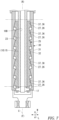
- the mandrel 3 includes a main shaft 10 rotated by receiving the rotational force from the first rotating mechanism 5, the expansion mechanism 20 supported by the main shaft 10 and expanding or collapsing the diameter of the segments 30, and the plurality of segments (winding drum) 30 winding the metal strip SR.
- the main shaft 10 includes a first shaft section 11 supported by the holding hollow shaft 53 as a component of the first rotating mechanism 5, and a second shaft section 15 relating to diameter expansion or diameter collapsing of the segments 30 and supporting the segments 30.
- the main shaft 10 includes a locking groove 14 into which a fixing ring 58 for positioning the mandrel 3 in a direction of an axis C relative to the first rotating mechanism 5, at a boundary part between the first shaft section 11 and the second shaft section 15. Note that the direction of the axis C is referred to as an axial direction C in some cases.
- the first shaft section 11 is provided on the rear side (R) of the locking groove 14, and the second shaft section 15 is provided on the front side (F) of the locking groove 14.
- the main shaft 10 is formed of a cylindrical member including a void around the axis C from the first shaft section 11 to the second shaft section 15. Except for a portion housing a hydraulic rotating cylinder 21, the void is equal in opening diameter from the first shaft section 11 to the second shaft section 15. However, an outer diameter of the main shaft 10 is smaller at the second shaft section 15 than at the first shaft section 11. A rod 23 of the expansion mechanism 20 is inserted into the void. Note that the first shaft section 11 and the second shaft section 15 may be integrally configured from beginning, or may be separately fabricated and then joined and integrated.
- the main shaft 10 is fixed so as not to rotate relative to the holding hollow shaft 53 rotated by the rotational forces of the main driving sources 9A and 9B, and rotates together with the holding hollow shaft 53.
- the metal strip SR is wound on the segments 30 provided on the main shaft 10.
- the outer diameter of the first shaft section 11 is reduced from the front side (F) to the rear side (R) in a stepwise manner. This is for convenience when the mandrel 3 used so far is removed for maintenance and a new mandrel 3 is inserted. More specifically, as illustrated in FIG. 5 and FIG. 6 , the outer diameter of the first shaft section 11 is set to be reduced in a stepwise manner in order of a first section A1 on the front side (F) of a bush 13, a second section A2 on the rear side (R) of the bush 13, and the rear side (R) of the second section A2.
- an opening diameter of a housing space AS of the holding hollow shaft 53 where the first shaft section 11 is disposed is set to be reduced in a stepwise manner from the front side (F) to the rear side (R).
- stepwise reduction in outer diameter and opening diameter is described; however, continuous reduction in outer diameter and opening diameter may be adopted. Since the outer diameter of the first shaft section 11 is reduced in a stepwise manner as described above, when the first shaft section 11 is mounted on the first rotating mechanism 5, a gap occurs between an outer peripheral surface of the first shaft section 11 and an inner peripheral surface of the holding hollow shaft 53. A portion where the gap occurs is excluded from a management object of a dimension tolerance between the first shaft section 11 and the holding hollow shaft 53.
- the first shaft section 11 includes a driven-side spline 12 (12A or 12B) and bushes 13 and 16.
- the driven-side spline 12A is referred to as the driven-side spline 12A
- the driven-side spline corresponding to the mandrel 3B is referred to as the driven-side spline 12B
- the driven-side splines 12A and 12B have the same configuration.
- each of the driven-side splines 12A and 12B is referred to as the driven-side spline 12 in the following description. Notation of characters A and B is also omitted for the other components in some cases.
- the driven-side spline 12 transmits the rotational force from the holding hollow shaft 53 to the first shaft section 11 of the main shaft 10.
- the driven-side spline 12 and a driving-side spline 55 of the holding hollow shaft 53 correspond to an example of a rotational force applying portion of the present disclosure in a spline fitting.
- the driven-side spline 12 includes a plurality of outer teeth provided on an outer periphery thereof, and the driving-side spline 55 includes inner teeth provided on an inner periphery thereof. Sliding in the axial direction C does not occur ideally between the driven-side spline 12 and the driving-side spline 55. Therefore, it is unnecessary to consider service lives of the driven-side spline 12 and the driving-side spline 55 caused by abrasion.
- the driven-side spline 12 is provided adjacent to the bush 13, between the bush 13 and the bush 16 in the direction of the axis C.
- the spline 12 is provided at a position close to the segments 30 to which the metal strip SR is wound.
- the segments 30 have a considerable weight including a weight of the wound metal strip SR. Therefore, a considerable torsional force is necessary to rotate the first shaft section 11.
- the torsional force is applied to the driven-side spline 12.
- a position receiving the torsional force is far from the segments 30, a torsional angle occurring on the second shaft section 15 provided with the segments 30 is increased. Therefore, the torsional angle is suppressed by providing the spline 12 at a position close to the segments 30.
- the driven-side spline 12 is provided at a region of the holding hollow shaft 53 having a large diameter as described below. Therefore, torsional rigidity is large. This makes it possible to suppress torsional stress occurring on the second shaft section 15.
- the bushes 13 and 16 are respectively provided at positions corresponding to bearings BB1 and BB2. Therefore, the spline 12 is disposed at a position close to the bearing BB1 on a side close to the segments 30.
- a key and a key groove can be used; however, the spline fitting is more advantageous for transmission of large rotational force than the key and key groove.
- the spline 12 and the driving-side spline 55 10 or more, furthermore, 20 or more teeth can be provided depending on the diameter. This makes it possible to realize transmission of larger rotational driving force. Presence of many teeth facilitates alignment between the teeth of the spline 12 and the teeth of the driving-side spline 55 in a circumferential direction, at replacement of the mandrel 3. For example, when the number of teeth is 12, the teeth of the spline 12 and the teeth of the driving-side spline 55 can be aligned only by rotating the spline 12 by up to 15 degrees.
- a straight-sided spline and an involute spline can be distinguished based on a cross-sectional shape of the teeth including concavities and convexities. Any form is applicable to the present embodiment; however, the involute spline is advantageous for transmission of larger rotational force, and can reduce backlash in a radial direction or can smoothly rotate even if slight backlash is present.
- the bushes 13 and 16 are provided between the first shaft section 11 and the holding hollow shaft 53 by being fitted to the first shaft section 11 of the main shaft 10.
- the first shaft section 11 is provided with the bushes 13 and 16 at a part on the front side (F) and at a part on the rear side (R), respectively, and both ends of the first shaft section 11 are supported to the holding hollow shaft 53 by the two bushes 13 and 16 in the radial direction.
- the main shaft 10 cannot rotate relative to the holding hollow shaft 53 in principle.
- sliding by a minute distance may occur between the first shaft section 11 and the holding hollow shaft 53 because a gap, namely, backlash of gears is present between the outer teeth of the spline 12 and the inner teeth of the driving-side spline 55 in the circumferential direction. Therefore, the bushes 13 and 16 are provided on the first shaft section 11, and the bushes 13 and 16 and the holding hollow shaft 53 are caused to slide with each other to generate abrasion on the bushes 13 and 16.
- the bushes 13 and 16 are replaceably mounted on the first shaft section 11 by, for example, shrink fitting. Therefore, when the bushes 13 and 16 are removed together with the mandrel 3 from the winding device 1 at replacement of the mandrel 3, the bushes 13 and 16 are replaced with new bushes 13 and 16.
- the bushes 13 and 16 are used as slide bearings, and are preferably made of a metal material excellent in sliding property, such as a copper alloy and an aluminum alloy, but may be made of a resin material or a ceramic material.
- the bushes 13 and 16 are provided at positions corresponding to the paired bearings BB1 and BB2 supporting the holding hollow shaft 53 (53A or 53B) described below.
- the winding device 1 includes bearings in addition to the bearings BB1 and BB2; however, illustration of reference numerals of the other bearings is omitted in order to avoid complication of the drawings.
- the second shaft section 15 is a hollow member that communicates with the first shaft section 11 and extends to the front side (F).
- Wedges 25 that expands or collapses the diameter of the segments 30 is provided around the second shaft section 15 that has an outer diameter less than the outer diameter of the first shaft section 11.
- the wedges 25 are slidably fitted to an outer peripheral surface of the second shaft section 15, and are fixed to the rod 23 of the expansion mechanism 20 through a fixing ring 17 on the front side (F) of an end part of the second shaft section 15 on the front side (F).
- the wedges 25 are ones of components of the expansion mechanism 20, and move in the axial direction C with movement of the expansion mechanism 20.
- the wedges 25 are members each including a plurality of tapered protrusions in the axial direction of the second shaft section 15, and the plurality of wedges 25 are combined in the circumferential direction of the second shaft section 15 to form the hollow member.
- the wedges 25 and the segments 30 configure a translation cam, and the diameter of the segments 30 as a follower is expanded or collapsed with movement of the wedges 25 as a driver in the axial direction C.
- the configurations of the wedges 25 are described in detail in description of the expansion mechanism 20. Movement in the axial direction C includes movement from the front side (F) to the rear side (R) and movement from the rear side (R) to the front side (F).
- a cylinder space 19 that is a void where the hydraulic rotating cylinder 21 configuring the expansion mechanism 20 and the rod 23 connecting with the hydraulic rotating cylinder 21 are disposed is provided along the direction of the axis C.
- the cylinder space 19 includes a cylinder space 19A where the hydraulic rotating cylinder 21 is disposed, and a rod space 19B where the rod 23 is disposed.
- An end part of the cylinder space 19A on the rear side (R) is closed, whereas an end part on the front side (F) communicates with the rod space 19B.
- An end part of the rod space 19B on the front side (F) is opened, and an end part of the rod 23 on the front side (F) protrudes.
- the hydraulic rotating cylinder 21 and the rod 23 are provided inside the main shaft 10.
- the hydraulic rotating cylinder 21 is provided inside the first shaft section 11 having a large diameter
- the rod 23 is provided inside the first shaft section 11 and the second shaft section 15 having a small diameter. Accordingly, the hydraulic rotating cylinder 21 including the rod 23 has a dimension in the radial direction falling within a range of the outer diameter of the main shaft 10.
- the expansion mechanism 20 includes the hydraulic rotating cylinder 21 as a driving source for moving the wedges 25 in the axial direction C, and the rod 23 moving in the axial direction C relative to the hydraulic rotating cylinder 21.
- the hydraulic rotating cylinder 21 is housed in the cylinder space 19A, and the rod 23 is inserted into the rod space 19B.
- the rod 23 protrudes from the end part of the rod space 19B on the front side (F), and a protruding portion of the rod 23 is connected and fixed to the wedges 25 through the fixing ring 17.
- the hydraulic rotating cylinder 21 operated by oil pressure or air pressure is merely an example of a driving source moving the wedges 25 in the axial direction C, and other driving source moving the wedges 25, for example, a linear electric motor can be used.
- the wedges 25 each include a plurality of cam protrusions 26 communicating in a circumferential direction.
- the plurality of cam protrusions 26 are provided over the substantially entire length of each of the wedges 25 in the direction of the axis C.
- each of the wedge shapes 26 has a shape in which a diameter is continuously increased from the rear side (R) to the front side (F), and is steeply reduced from a vertex of the diameter.
- An outer peripheral surface of a portion where the diameter is enlarged configures a cam surface 27 that comes into contact with and slides with a cam surface 37 of the segments 30 at diameter enlargement or diameter reduction.
- the segments 30 are disposed to surround a periphery of the second shaft section 15 with the wedges 25 in between.
- four segments 30 surround the periphery of the second shaft section 15 to configure the winding drum.
- a center angle of each of the segments 30 each having an arc-shaped cross-section is 90 degrees.
- a circular cross-section is formed.
- the segments 30 are coupled to the second shaft section 15 of the main shaft 10 so as to be displaceable in the radial direction of the second shaft section 15.
- an outer diameter of the winding drum specified by the outer peripheral surfaces of the segments 30 is expanded, whereas when the segments 30 are displaced inward in the radial direction from those positions, the outer diameter of the winding drum is reduced.
- Outer surfaces 31 of the segments 30 each have an arc surface equal in diameter in the direction of the axis C.
- inner surfaces 32 are provided with a plurality of cam grooves 36 to which the respective cam protrusions 26 of the wedges 25 enter.
- each of the wedge grooves 36 has a shape in which a diameter is continuously increased from the rear side (R) to the front side (F), and is steeply reduced from a vertex of the diameter.
- the inner surface 32 of a portion where the diameter is expanded configures the wedge surface 37 that comes into contact with and slides with the wedge surface 27 of the wedges 25 at diameter expansion or diameter collapsing.
- the first rotating mechanism 5 holds the mandrels 3A and 3B, and transmits the rotational forces from the main driving sources 9A and 9B to the mandrels 3A and 3B.
- the first rotating mechanism 5 includes a casing 51, the paired holding hollow shafts 53A and 53B provided with an interval in a width direction (W) of the casing 51, and main pinions 54A and 54B respectively provided on the holding hollow shafts 53A and 53B.
- Each of the main pinions 54A and 54B is an example of a rotational force receiving section of the present disclosure.
- Main driving shafts 77A and 77B transmitting rotational forces from the gear reducers 7A and 7B are disposed in the casing 51 so as to penetrate the casing 51 in a front-rear direction.
- the main driving shafts 77A and 77B are disposed at a center part of the casing 51 in the width direction (W), and the holding hollow shafts 53A and 53B are disposed on both sides of the main driving shafts 77A and 77B in the width direction (W).
- the main driving shafts 77A and 77B are supported by a plurality of bearings so as to be rotatable to the casing 51.
- the holding hollow shaft 53A insertably and removably holds the mandrel 3A
- the holding hollow shaft 53B insertably and removably holds the mandrel 3B.
- the mandrels 3A and 3B are respectively removed from the holding hollow shafts 53A and 53B, and new maintained mandrels 3A and 3B are respectively mounted on the holding hollow shafts 53A and 53B.
- Each of the holding hollow shafts 53A and 53B is supported to the casing 51 in the radial direction by the bearings BB1 and BB2 rotatable to the casing 51.
- the paired bearings BB1 and BB2 are provided at parts on the front side (F) and the rear side (R), of each of the holding hollow shafts 53A and 53B.
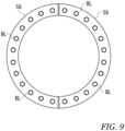
- the end parts of the mandrels 3A and 3B on the rear side (R) in the axial direction C are restrained in the front-rear direction by cylindrical fixing rings 57 fixed to the casing 51, and the end parts of the mandrels 3A and 3B on the front side (F) in the axial direction C are restrained in the front-rear direction by cylindrical fixing rings 58 insertable into / removable from the casing 51.
- the fixing rings 58 each having a half-divided structure as illustrated in FIG.
- the main pinion 54A is fitted to the holding hollow shaft 53A, and the main pinion 54B is fitted to the holding hollow shaft 53B.
- the main pinion 54A meshes with a main gear 81A fitted to the main driving shaft 77A on the rear side (R), and the main pinion 54B meshes with a main gear 81B fitted to the main driving shaft 77B on the front side (F).
- a driving-side spline 55A meshing with the driven-side spline 12A is provided on the holding hollow shaft 53A
- a driving-side spline 55B meshing with the driven-side spline 12B is provided on the holding hollow shaft 53B.
- the holding hollow shaft 53A is rotated through the main pinion 54A and the main gear 81A or the holding hollow shaft 53B is rotated through the main pinion 54B and the main gear 81B.
- Rotating the holding hollow shaft 53A rotates the mandrel 3A through the driving-side spline 55A and the driven-side spline 12A
- rotating the holding hollow shaft 53B rotates the mandrel 3B through the driving-side spline 55B and the driven-side spline 12B.
- the main pinions 54A and 54B of the holding hollow shafts 53A and 53B receive the rotational forces from the main driving shafts 77A and 77B.
- Each of the driven-side splines 12A and 12B is disposed at a position close to the bearing BB1 on a side close to the winding drum including the segments 30 separated from a corresponding one of the main pinions 54A and 54B, out of the paired bearings BB1 and BB2 supporting a corresponding one of the holding hollow shafts 53A and 53B.
- the position corresponds to a region where the diameters of the first shaft section 11 and the holding hollow shaft 53 are large.
- the second rotating mechanism 6 rotatably supports the first rotating mechanism 5.
- the second rotating mechanism 6 rotates the first rotating mechanism 5 to enable start of winding of the metal strip SR by the other mandrel 3B. More specifically, the second rotating mechanism 6 rotates the first rotating mechanism 5 by 180 degrees such that, in FIG. 1 , the mandrel 3A reaches the position of the mandrel 3B and the mandrel 3B reaches the position of the mandrel 3A.
- the second rotating mechanism 6 includes a base 61, and a driving gear 63 and an idling roller 65 provided with an interval in the width direction (W) on the base 61.
- a driven gear 59 of the first rotating mechanism 5 is placed on the driving gear 63 and the idling roller 65.
- the driving gear 63 rotates, for example, in a clockwise direction by an unillustrated electric motor.
- the driving gear 63 includes a plurality of teeth on an outer peripheral surface, and the teeth of the driving gear 63 mesh with teeth of the driven gear 59.
- the idling roller 65 is rotatably supported by the base 61 through unillustrated bearings.
- the idling roller 65 has a flat outer peripheral surface.
- the gear reducer 7A reduces rotation of the main driving source 9A and transmits the reduced rotation to the holding hollow shaft 53A
- the gear reducer 7B reduces rotation of the main driving source 9B and transmits the reduced rotation to the holding hollow shaft 53B.
- the gear reducer 7A includes a gear case 71A, a first gear 73A rotatably supported by the gear case 71A through bearings, a second gear 74A rotatably supported by the gear case 71A through bearings, and a third gear 75A rotatably supported by the gear case 71 through bearings.
- the first gear 73A meshes with the second gear 74A
- the second gear 74A meshes with the third gear 75A.
- a drive coupling 91A of the main driving source 9A is coaxially fixed to the first gear 73A
- the main driving shaft 77A extending up to the first rotating mechanism 5 is coaxially fixed to the third gear 75A.
- the main pinion 54A is coaxially fixed to the main driving shaft 77A as described above.
- the gear reducer 7B includes a gear case 71B, a first gear 73B rotatably supported by the gear case 71B through bearings, and a second gear 74B rotatably supported by the gear case 71 through bearings.
- the first gear 73B meshes with the second gear 74B.
- a drive coupling 91B of the main driving source 9B is coaxially fixed to the first gear 73B, and the main driving shaft 77B extending up to the first rotating mechanism 5 is coaxially fixed to the second gear 74B.
- the main pinion 54B is coaxially fixed to the main driving shaft 77B as described above.
- Each of the main driving shaft 77A and the main driving shaft 77B has a cylindrical form, and the main driving shaft 77A is provided in a void inside the main driving shaft 77B.
- a supporting shaft 79 in which both ends are fixed and supported is provided in a void inside the main driving shaft 77A.
- the main driving shaft 77B is rotatable around the supporting shaft 79, and the main driving shaft 77A is rotatable around the main driving shaft 77B.
- the main driving source 9A When the metal strip SR is wound on the mandrel 3A, the main driving source 9A is driven, and rotational force of the main driving source 9A is transmitted to the gear reducer 7A through the drive coupling 91A.
- the rotational force transmitted to the gear reducer 7A is transmitted to the main driving shaft 77A, and further rotates the mandrel 3A through the main pinion 54A and the driving-side spline 55A. At this time, operation of the main driving source 9B is stopped.
- the main driving source 9B When the metal strip SR is wound on the mandrel 3B, the main driving source 9B is driven, and rotational force of the main driving source 9B is transmitted to the gear reducer 7B through the driving shaft 91B.
- the rotational force transmitted to the gear reducer 7B is transmitted to the main driving shaft 77B, and further rotates the mandrel 3B through the main pinion 54B and the driving-side spline 55B. At this time, operation of the main driving source 9A is stopped.
- the fixing ring 58 is first removed.
- the fixing ring 58 restraint of the mandrel 3B to the front side (F) is released. Therefore, the mandrel 3B can be removed from the holding hollow shaft 53B of the first rotating mechanism 5 by being moved to the front side (F).
- the fixing ring 58 is fixed to the holding hollow shaft 53B by the fastening means. The work for replacing the mandrel 3B is thus finished.
- the removed mandrel 3B is subjected to maintenance such as replacement of the segments 30.
- the coil CL formed by winding the metal strip SR by the mandrel 3 is removed from the mandrel 3.
- an unillustrated carriage is used. More specifically, the carriage is moved to the mandrel 3 to receive the coil CL. After the mandrel 3 is reduced in diameter to release restraint of the coil CL, the carriage is moved to remove the coil CL from the mandrel 3. At the removal, it is necessary to prevent the coil CL from becoming a telescopic shape, and the coil CL is not easily removed from the mandrel 3 in some cases. To cope with such defects, the winding device 1 includes a removal assisting mechanism 100.
- the removal assisting mechanism 100 includes a stripper plate 101 that comes into contact with a part of the coil CL on the rear side (R) to press the coil CL, and a driving source 103 that moves the stripper plate 101 from a standby position illustrated by a solid line to a removal position illustrated by an alternate long and short dash line.
- the removal assisting mechanism 100 When the coil CL is removed from the mandrel 3, the removal assisting mechanism 100 operates the driving source 103 and advances the stripper plate 101 from the standby position to the removal position. In this way, the removal assisting mechanism 100 copes with the defects when the coil CL is removed from the mandrel 3.
- the expansion mechanism 20 changing the outer diameter of the mandrel 3 and the mandrel 3 are integrally insertable into and removal from the holding hollow shaft 53 in the axial direction of the mandrel.
- the expansion mechanism 20 can also be removed together with the mandrel. This makes it possible to easily replace the mandrel 3 in a short time.
- the hydraulic rotating cylinder 21 including the rod 23 has the dimension in the radial direction falling within the range of the outer diameter of the main shaft 10.
- the hydraulic rotating cylinder 21 including the rod 23 is provided inside the main shaft 10. Therefore, according to the winding device 1, at replacement of the mandrel 3, the hydraulic rotating cylinder 21 and the rod 23 can be removed together with the mandrel 3 while avoiding interference with the holding hollow shaft 53. This makes it possible to easily replace the mandrel in a short time.
- the first shaft section 11 supported by the bearings BB1 and BB2 through the holding hollow shaft 53 has the cylindrical appearance. Therefore, according to the winding device 1, a moment arm of an overturning moment acting on the winding drum including the segments 30 of the mandrel 3 is increased, and reaction force acting on the cylindrical first shaft section 11 and surface pressure generated by the reaction force can be reduced. This makes it possible to considerably reduce a risk of wear such as abrasion and settling, of the first shaft section 11.
- the bushes 13 and 16 are insertably and removably fitted at the positions facing the paired bearings BB1 and BB2. Therefore, according to the winding device 1, periodically replacing the bushes 13 and 16, for example, at replacement of the mandrel 3 makes it possible to maintain the winding device 1 at a small maintenance cost without damaging the first shaft section 11.
- the portions facing the bearings BB1 and BB2 receive heavy loads and are easily worn. Therefore, using the replaceable bushes 13 and 16 for the portions makes it possible to reduce wear of the mandrel 3 and to improve durability.
- the spline including the driven-side spline 12 and the driving-side spline 55 is adopted as the rotational force applying portion.
- the spline is high in transmission torque.
- the inner teeth of the holding hollow shaft 53 and the outer teeth of the first shaft section 11 can be caused to mesh with each other only by small rotation in the circumferential direction. Therefore, the main shaft 10 can be easily mounted on the holding hollow shaft 53.
- a function sharing system in which the bushes 13 and 16 hold a radial load and the spline transmits the torque is adopted, which makes it possible to minimize the gap between the first shaft section 11 of the main shaft 10 and the holding hollow shaft 53.
- the holding hollow shaft 53 includes the main pinion 54 as the rotational force receiving section to which the rotational force is transmitted, and the driven-side spline 12 is disposed at the position close to the bearing BB1 on the side close to the winding drum including the segments 30, out of the paired bearings BB1 and BB2.
- the segments (winding drum) 30 have the considerable weight including the weight of the wound metal strip SR. Therefore, the considerable torsional force is necessary to rotate the first shaft section 11.
- the torsional force is applied to the driven-side spline 12.
- the torsional angle occurring on the second shaft section 15 provided with the segments 30 is increased. Therefore, in the winding device 1, the torsional angle is suppressed by providing the driven-side spline 12 at the position close to the segments 30. Further, the driven-side spline 12 is provided at the region of the holding hollow shaft 53 having the large diameter. Therefore, torsional rigidity is large.
- the outer diameter of the first shaft section 11 and the opening diameter of the housing space AS is gradually reduced to the rear side (R). Therefore, at replacement of the mandrel 3, the first shaft section 11 of the mandrel 3 is easily inserted into the holding hollow shaft 53.
- the coil removal assisting mechanism 100 pressing the end surface of the coil CL is provided. Therefore, at removal of the coil CL from the mandrel 3, it is possible to prevent the coil CL from being unwound and becoming a telescopic shape, and to prevent the coil CL from becoming difficult to be removed.
- the hydraulic rotating cylinder 21 is used as the driving source for expanding or collapsing the diameter of the segments 30.
- the driving source is not limited as long as the driving source can expand or collapse the diameter of the segments 30, and other driving source such as a linear electric motor can be used.
- the gear reducers 7A and 7B are interposed between the main driving sources 9A and 9B and the first rotating mechanism 5; however, a driving source having functions corresponding to the gear reducers 7A and 7B can be used.
Landscapes
- Engineering & Computer Science (AREA)
- Mechanical Engineering (AREA)
- Winding Of Webs (AREA)
Applications Claiming Priority (1)
| Application Number | Priority Date | Filing Date | Title |
|---|---|---|---|
| PCT/JP2022/020961 WO2023223544A1 (fr) | 2022-05-20 | 2022-05-20 | Dispositif d'enroulement, procédé de remplacement de mandrin et mandrin |
Publications (2)
| Publication Number | Publication Date |
|---|---|
| EP4501829A1 true EP4501829A1 (fr) | 2025-02-05 |
| EP4501829A4 EP4501829A4 (fr) | 2025-05-14 |
Family
ID=88834934
Family Applications (1)
| Application Number | Title | Priority Date | Filing Date |
|---|---|---|---|
| EP22942748.9A Pending EP4501829A4 (fr) | 2022-05-20 | 2022-05-20 | Dispositif d'enroulement, procédé de remplacement de mandrin et mandrin |
Country Status (4)
| Country | Link |
|---|---|
| EP (1) | EP4501829A4 (fr) |
| JP (1) | JP7776631B2 (fr) |
| CN (1) | CN119032056A (fr) |
| WO (1) | WO2023223544A1 (fr) |
Family Cites Families (9)
| Publication number | Priority date | Publication date | Assignee | Title |
|---|---|---|---|---|
| US2117640A (en) * | 1936-11-24 | 1938-05-17 | Wean Engineering Co Inc | Coiling reel |
| DE2120741B2 (de) * | 1971-04-28 | 1975-06-12 | Demag Ag, 4100 Duisburg | Verstellantrieb für die Spreizsegmente des Wickeldorns eines Haspels für gewalztes Band |
| AT343586B (de) * | 1976-02-26 | 1978-06-12 | Voest Ag | Haspel, insbesondere fur blechbander |
| JPS6061116A (ja) * | 1983-09-14 | 1985-04-08 | Mitsubishi Heavy Ind Ltd | 軸受温度制御機構を具えた回転軸構造 |
| JP2516486Y2 (ja) * | 1990-04-13 | 1996-11-06 | 日下部電機株式会社 | パイロットチェック弁付き回転油路継手 |
| FR2749783B1 (fr) * | 1996-06-14 | 1998-09-11 | Clecim Sa | Bobineuse a carrousel |
| JP2007191301A (ja) * | 2006-01-17 | 2007-08-02 | Pubot Giken:Kk | 保持シャフト |
| CN102284556B (zh) * | 2011-07-11 | 2014-06-18 | 武汉钢铁(集团)公司 | 冷轧带钢大型卷取机卷筒 |
| KR102200891B1 (ko) | 2020-06-30 | 2021-01-11 | 주식회사 서울엔지니어링 | 이중 유압 공급이 가능한 스트립 권취 장치 |
-
2022
- 2022-05-20 EP EP22942748.9A patent/EP4501829A4/fr active Pending
- 2022-05-20 JP JP2024521515A patent/JP7776631B2/ja active Active
- 2022-05-20 WO PCT/JP2022/020961 patent/WO2023223544A1/fr not_active Ceased
- 2022-05-20 CN CN202280095567.4A patent/CN119032056A/zh active Pending
Also Published As
| Publication number | Publication date |
|---|---|
| WO2023223544A1 (fr) | 2023-11-23 |
| JPWO2023223544A1 (fr) | 2023-11-23 |
| EP4501829A4 (fr) | 2025-05-14 |
| JP7776631B2 (ja) | 2025-11-26 |
| CN119032056A (zh) | 2024-11-26 |
Similar Documents
| Publication | Publication Date | Title |
|---|---|---|
| KR101084539B1 (ko) | 축 지지구조 및 감속장치 | |
| KR950010687B1 (ko) | 유성치차 증감속기 | |
| CZ336292A3 (en) | Rolling mill stand | |
| US20100130324A1 (en) | Coaxial transmission | |
| CN112547947B (zh) | 复合坯料外管旋压缩口设备 | |
| EP4501829A1 (fr) | Dispositif d'enroulement, procédé de remplacement de mandrin et mandrin | |
| CN109834133B (zh) | 一种可防止钢卷塔卷的开卷机 | |
| UA116314C2 (uk) | Пристрій і спосіб для змотування штабового матеріалу | |
| EP0845311A1 (fr) | Dispositif de formage d'une coquille de silencieux | |
| JP2012040587A (ja) | リングローリングミル | |
| CA2877173A1 (fr) | Formation de cannelures helicoidales | |
| EP2834021B1 (fr) | Dispositif d'entraînement pour transmettre un mouvement à un cylindre | |
| US3294338A (en) | Reel for strip material | |
| WO1999054064A1 (fr) | Laminoir multifonctions pour laminer des profiles en h, equipement et procede correspondants | |
| CN110653286B (zh) | 无内应力的多头螺旋盘管机 | |
| CN218835598U (zh) | 用于皮尔格冷轧机的送进小车 | |
| EP2207636B1 (fr) | Dispositif d'entraînement en rotation | |
| CN223028152U (zh) | 一种开卷机 | |
| JP3429636B2 (ja) | ロール幅調整装置 | |
| CN221848245U (zh) | 一种开卷机涨缩结构 | |
| RU2447959C2 (ru) | Устройство для привода во вращение | |
| CN215467165U (zh) | 一种一体轴滑动套式冷轧卷筒 | |
| CN219966038U (zh) | 重型双锥开卷机 | |
| JPH07246417A (ja) | 複胴型の巻取り・巻戻し装置 | |
| JPH06254608A (ja) | 3ロールパイピングミル |
Legal Events
| Date | Code | Title | Description |
|---|---|---|---|
| STAA | Information on the status of an ep patent application or granted ep patent |
Free format text: STATUS: THE INTERNATIONAL PUBLICATION HAS BEEN MADE |
|
| PUAI | Public reference made under article 153(3) epc to a published international application that has entered the european phase |
Free format text: ORIGINAL CODE: 0009012 |
|
| STAA | Information on the status of an ep patent application or granted ep patent |
Free format text: STATUS: REQUEST FOR EXAMINATION WAS MADE |
|
| 17P | Request for examination filed |
Effective date: 20241021 |
|
| AK | Designated contracting states |
Kind code of ref document: A1 Designated state(s): AL AT BE BG CH CY CZ DE DK EE ES FI FR GB GR HR HU IE IS IT LI LT LU LV MC MK MT NL NO PL PT RO RS SE SI SK SM TR |
|
| A4 | Supplementary search report drawn up and despatched |
Effective date: 20250411 |
|
| RIC1 | Information provided on ipc code assigned before grant |
Ipc: B65H 75/24 20060101ALI20250408BHEP Ipc: B21C 47/30 20060101ALI20250408BHEP Ipc: B21C 47/24 20060101ALI20250408BHEP Ipc: B65H 18/04 20060101AFI20250408BHEP |
|
| DAV | Request for validation of the european patent (deleted) | ||
| DAX | Request for extension of the european patent (deleted) | ||
| STAA | Information on the status of an ep patent application or granted ep patent |
Free format text: STATUS: EXAMINATION IS IN PROGRESS |
|
| 17Q | First examination report despatched |
Effective date: 20260204 |