EP4501874A1 - Optisches glas, optisches element, wechselobjektiv für eine kamera, objektiv, sinterobjektiv, optisches system, spiegelelement und positionsmesseinrichtung - Google Patents
Optisches glas, optisches element, wechselobjektiv für eine kamera, objektiv, sinterobjektiv, optisches system, spiegelelement und positionsmesseinrichtung Download PDFInfo
- Publication number
- EP4501874A1 EP4501874A1 EP23779081.1A EP23779081A EP4501874A1 EP 4501874 A1 EP4501874 A1 EP 4501874A1 EP 23779081 A EP23779081 A EP 23779081A EP 4501874 A1 EP4501874 A1 EP 4501874A1
- Authority
- EP
- European Patent Office
- Prior art keywords
- content rate
- optical
- lens
- optical glass
- mol
- Prior art date
- Legal status (The legal status is an assumption and is not a legal conclusion. Google has not performed a legal analysis and makes no representation as to the accuracy of the status listed.)
- Pending
Links
Images



Classifications
-
- C—CHEMISTRY; METALLURGY
- C03—GLASS; MINERAL OR SLAG WOOL
- C03C—CHEMICAL COMPOSITION OF GLASSES, GLAZES OR VITREOUS ENAMELS; SURFACE TREATMENT OF GLASS; SURFACE TREATMENT OF FIBRES OR FILAMENTS MADE FROM GLASS, MINERALS OR SLAGS; JOINING GLASS TO GLASS OR OTHER MATERIALS
- C03C3/00—Glass compositions
- C03C3/12—Silica-free oxide glass compositions
- C03C3/122—Silica-free oxide glass compositions containing oxides of As, Sb, Bi, Mo, W, V, Te as glass formers
-
- C—CHEMISTRY; METALLURGY
- C03—GLASS; MINERAL OR SLAG WOOL
- C03C—CHEMICAL COMPOSITION OF GLASSES, GLAZES OR VITREOUS ENAMELS; SURFACE TREATMENT OF GLASS; SURFACE TREATMENT OF FIBRES OR FILAMENTS MADE FROM GLASS, MINERALS OR SLAGS; JOINING GLASS TO GLASS OR OTHER MATERIALS
- C03C3/00—Glass compositions
- C03C3/12—Silica-free oxide glass compositions
- C03C3/14—Silica-free oxide glass compositions containing boron
-
- C—CHEMISTRY; METALLURGY
- C03—GLASS; MINERAL OR SLAG WOOL
- C03C—CHEMICAL COMPOSITION OF GLASSES, GLAZES OR VITREOUS ENAMELS; SURFACE TREATMENT OF GLASS; SURFACE TREATMENT OF FIBRES OR FILAMENTS MADE FROM GLASS, MINERALS OR SLAGS; JOINING GLASS TO GLASS OR OTHER MATERIALS
- C03C3/00—Glass compositions
- C03C3/12—Silica-free oxide glass compositions
- C03C3/14—Silica-free oxide glass compositions containing boron
- C03C3/15—Silica-free oxide glass compositions containing boron containing rare earths
-
- C—CHEMISTRY; METALLURGY
- C03—GLASS; MINERAL OR SLAG WOOL
- C03C—CHEMICAL COMPOSITION OF GLASSES, GLAZES OR VITREOUS ENAMELS; SURFACE TREATMENT OF GLASS; SURFACE TREATMENT OF FIBRES OR FILAMENTS MADE FROM GLASS, MINERALS OR SLAGS; JOINING GLASS TO GLASS OR OTHER MATERIALS
- C03C3/00—Glass compositions
- C03C3/12—Silica-free oxide glass compositions
- C03C3/14—Silica-free oxide glass compositions containing boron
- C03C3/15—Silica-free oxide glass compositions containing boron containing rare earths
- C03C3/155—Silica-free oxide glass compositions containing boron containing rare earths containing zirconium, titanium, tantalum or niobium
-
- G—PHYSICS
- G02—OPTICS
- G02B—OPTICAL ELEMENTS, SYSTEMS OR APPARATUS
- G02B1/00—Optical elements characterised by the material of which they are made; Optical coatings for optical elements
-
- G—PHYSICS
- G02—OPTICS
- G02B—OPTICAL ELEMENTS, SYSTEMS OR APPARATUS
- G02B13/00—Optical objectives specially designed for the purposes specified below
- G02B13/001—Miniaturised objectives for electronic devices, e.g. portable telephones, webcams, PDAs, small digital cameras
- G02B13/0055—Miniaturised objectives for electronic devices, e.g. portable telephones, webcams, PDAs, small digital cameras employing a special optical element
- G02B13/006—Miniaturised objectives for electronic devices, e.g. portable telephones, webcams, PDAs, small digital cameras employing a special optical element at least one element being a compound optical element, e.g. cemented elements
-
- G—PHYSICS
- G02—OPTICS
- G02B—OPTICAL ELEMENTS, SYSTEMS OR APPARATUS
- G02B21/00—Microscopes
- G02B21/02—Objectives
- G02B21/04—Objectives involving mirrors
-
- G—PHYSICS
- G02—OPTICS
- G02B—OPTICAL ELEMENTS, SYSTEMS OR APPARATUS
- G02B7/00—Mountings, adjusting means, or light-tight connections, for optical elements
- G02B7/02—Mountings, adjusting means, or light-tight connections, for optical elements for lenses
- G02B7/14—Mountings, adjusting means, or light-tight connections, for optical elements for lenses adapted to interchange lenses
Definitions
- the present invention relates to optical glass, an optical element, an interchangeable camera lens, a microscope objective lens, a cemented lens, an optical system, an optical device, a reflective element, and a position measuring device.
- the present invention claims priority to Japanese Patent Application No. 2022-053320, filed on March 29, 2022 , the contents of which are incorporated by reference herein in its entirety in designated states where the incorporation of documents by reference is approved.
- optical glass that has a refractive index of approximately 2 in the near-infrared range while having a high refractive index, high dispersion, and low abnormal dispersion has been demanded as an optical glass to be used for such equipment.
- a first aspect according to the present invention is an optical glass containing, by mol%, 40 to 85% of a content rate of TeO 2 , 10 to 40% of a content rate of ZnO, at least one of B 2 O 3 and Bi 2 O 3 , and at least one of La 2 O 3 and WO 3 .
- An optical glass contains, by mol%, 40 to 85% of a content rate of TeO 2 , 10 to 40% of a content rate of ZnO, 0 to 10% of a content rate of B 2 O 3 , 0 to 10% of a content rate of Bi 2 O 3 , and at least one of Y 2 O 3 , La 2 O 3 , and Gd 2 O 3 .
- a second aspect according to the present invention is an optical element using the optical glass described above.
- a third aspect according to the present invention is an optical device including the optical element described above.
- a fourth aspect according to the present invention is a reflective element including the optical element described above.
- a fifth aspect according to the present invention is a position measuring device including the reflective element described above.
- a sixth aspect according to the present invention is an interchangeable camera lens including the optical element described above.
- a seventh aspect according to the present invention is a microscope objective lens including the optical element described above.
- An eighth aspect according to the present invention is a cemented lens including a first lens element and a second lens element, wherein at least one of the first lens element and the second lens element is the optical glass described above.
- a ninth aspect according to the present invention is an optical system including the cemented lens described above.
- a tenth aspect according to the present invention is an interchangeable camera lens including the optical system described above.
- An eleventh aspect according to the present invention is a microscope objective lens including the optical system described above.
- a twelfth aspect according to the present invention is an optical device including the optical system described above.
- present embodiment description is made on an embodiment of the present invention (hereinafter, referred to as the "present embodiment").
- the present embodiment described below is an example for describing the present invention, and is not intended to limit the present invention to the contents described below.
- the present invention may be modified as appropriate and carried out without departing from the gist thereof.
- An optical glass according to the present embodiment is an optical glass containing, by mol%, 40 to 85% of a content rate of TeO 2 , 10 to 40% of a content rate of ZnO, at least one of B 2 O 3 and Bi 2 O 3 , and at least one of La 2 O 3 and WO 3 .
- An optical glass contains, by mol%, 40 to 85% of a content rate of TeO 2 , 10 to 40% of a content rate of ZnO, 0 to 10% of a content rate of B 2 O 3 , 0 to 10% of a content rate of Bi 2 O 3 , and at least one of Y 2 O 3 , La 2 O 3 , and Gd 2 O 3 .
- the oxide-converted composition described herein is a composition in which each component contained in the glass is expressed with a total molar number of the oxides as 100 mol%.
- a content rate of Q is "from 0 to N%" is an expression including a case in which the component Q is not contained and a case in which the content rate of the component Q exceeds 0% and is equal to or less than N%.
- the component Q is not contained
- the level substantially equal to or less than that of impurities means, for example, less than 0.01%.
- devitrification resistance stability means resistance of the glass with respect to devitrification.
- devitrification means a phenomenon where the glass loses transparency due to crystallization, phase separation, or the like that occurs when the glass is heated above the glass transition temperature or is cooled below the liquid phase temperature from a molten state.
- the optical glass according to the present embodiment can be achieved as an optical glass that has a refractive index of approximately 2 in the near-infrared range while having a high refractive index, high dispersion, and low abnormal dispersion.
- TeO 2 is a component that can improve the refractive index and the devitrification resistance stability. From such a viewpoint, by mol%, a content rate of TeO 2 is from 40 to 85%. A lower limit of this content rate is preferably 45%, more preferably 47%, further preferably 50%. An upper limit of this content rate is preferably 80%, more preferably 70%, further preferably 65%.
- ZnO is a component that improves the devitrification resistance stability and reduces the partial dispersion ratio.
- a content rate of ZnO is excessively reduced, the devitrification resistance stability is likely to be degraded.
- a content rate of ZnO is excessively increased, the partial dispersion ratio is likely to be reduced.
- a content rate of ZnO is from 10 to 40%.
- a lower limit of this content rate is preferably 120, more preferably 15%, further preferably 18%.
- An upper limit of this content rate is preferably 350, more preferably 30%, further preferably 25%.
- the glass according to the present embodiment preferably contains at least one component of B 2 O 3 and Bi 2 O 3 in addition to TeO 2 and ZnO.
- B 2 O 3 when B 2 O 3 is contained, Bi 2 O 3 may or may not be added to the optical glass of the present embodiment.
- at least one component of La 2 O 3 and WO 3 is preferably contained.
- La 2 O 3 when La 2 O 3 is contained, WO 3 may or may not be added to the optical glass of the present embodiment.
- B 2 O 3 is a component that constitutes a network-forming oxide. Since B 2 O 3 is a highly volatile component, excessive introduction thereof may cause fluctuations in the composition of the glass during manufacturing, which may lead to the manifestation of stria. From such a viewpoint, by mol%, a content rate of B 2 O 3 is from 0 to 20%. A lower limit of this content rate is preferably 20, more preferably 40, further preferably 5%. An upper limit of this content rate is preferably 16%, more preferably 14%, further preferably 12%.
- Bi 2 O 3 is a component that improves the refractive index and the partial dispersion ratio.
- a content rate of Bi 2 O 3 is excessively increased, a transmittance is likely to be degraded, and dispersion is likely to be increased.
- a content rate of Bi 2 O 3 is excessively reduced, meltability is likely to be degraded.
- a content rate of Bi 2 O 3 is from 0 to 10%.
- a lower limit of this content rate is preferably 20, more preferably 30, further preferably 4%.
- An upper limit of this content rate is preferably 90, more preferably 80, further preferably 7%.
- La 2 O 3 exerts an effect of improving the refractive index without degrading low dispersion, and can maintain the devitrification resistance stability of the glass.
- the specific gravity thereof is likely to be increased.
- a content rate of La 2 O 3 is from 0 to 15%.
- a lower limit of this content rate is preferably 20, more preferably 40, further preferably 6%.
- An upper limit of this content rate is preferably 13%, more preferably 110, further preferably 10%.
- a content rate of WO 3 is from 0 to 20%.
- a lower limit of this content rate is preferably 20, more preferably 40, further preferably 6%.
- An upper limit of this content rate is preferably 18%, more preferably 16%, further preferably 14%.
- Y 2 O 3 is a component that can improve the refractive index without degrading low dispersion, and can further improve the devitrification resistance stability particularly when it coexists with La 3+ in the glass. From such a viewpoint, by mol%, a content rate of Y 2 O 3 is from 0 to 15%. A lower limit of this content rate is preferably 10, more preferably 20, further preferably 3%. An upper limit of this content rate is preferably 13%, more preferably 10%, further preferably 8%.
- Gd 2 O 3 is a component that can improve the refractive index without degrading low dispersion, and can further improve the devitrification resistance stability particularly when it coexists with La 3+ in the glass. From such a viewpoint, by mol%, a content rate of Gd 2 O 3 is from 0 to 15%. A lower limit of this content rate is preferably 10, more preferably 20, further preferably 3%. An upper limit of this content rate is preferably 13%, more preferably 10%, further preferably 8%.
- the optical glass according to the present embodiment preferably contains at least one of Y 2 O 3 , La 2 O 3 , and Gd 2 O 3 .
- a lower limit of this content rate preferably exceeds 0%, is more preferably 30, further preferably 4%.
- An upper limit of this content rate is preferably 13%, more preferably 110, further preferably 10%.
- Li 2 O is a component that reduces ⁇ P g, F and improves the glass meltability.
- a content rate of Li 2 O is from 0 to 10%.
- a lower limit of this content rate is preferably 10, more preferably 20, further preferably 3%.
- An upper limit of this content rate is preferably 80, more preferably 60, further preferably 5%.
- Na 2 O is a component that reduces ⁇ P g, F and improves the glass meltability.
- a content rate of Na 2 O is from 0 to 10%.
- a lower limit of this content rate is preferably 10, more preferably 20, further preferably 3%.
- An upper limit of this content rate is preferably 80, more preferably 60, further preferably 5%.
- K 2 O is a component that reduces ⁇ P g, F and improves the glass meltability, and exerts a great effect of degrading the devitrification resistance stability of the glass and increasing the abbe number as compared to Li 2 O and Na 2 O.
- a content rate of K 2 O is from 0 to 10%.
- a lower limit of this content rate is preferably 10, more preferably 20, further preferably 3%.
- An upper limit of this content rate is preferably 80, more preferably 60, further preferably 5%.
- a content rate of SrO is from 0 to 5%.
- a lower limit of this content rate is preferably 0.5%, more preferably 10, further preferably 2%.
- An upper limit of this content rate is preferably 40, more preferably 3.5%, further preferably 3%.
- BaO is a component that improves the devitrification resistance stability of the glass without significantly increasing ⁇ P g, F .
- a content rate of BaO is from 0 to 5%.
- a lower limit of this content rate is preferably 0.5%, more preferably 10, further preferably 2%.
- An upper limit of this content rate is preferably 40, more preferably 3.5%, further preferably 3%.
- a content rate of CaO is from 0 to 10%.
- a lower limit of this content rate is preferably 10, more preferably 20, further preferably 3%.
- An upper limit of this content rate is preferably 90, more preferably 80, further preferably 6%.
- MgO is a component that increases the abbe number, and exerts a great effect of increasing ⁇ P g, F as compared to BaO.
- a content rate of MgO is from 0 to 10%.
- a lower limit of this content rate is preferably 10, more preferably 20, further preferably 3%.
- An upper limit of this content rate is preferably 90, more preferably 80, further preferably 7%.
- Al 2 O 3 is a component that can improve meltability during manufacturing of the optical glass and the devitrification resistance stability of the optical glass. From such a viewpoint, by mol%, a content rate of Al 2 O 3 is from 0 to 5%. A lower limit of this content rate is preferably 0.5%, more preferably 10, further preferably 1.5%. An upper limit of this content rate is preferably 40, more preferably 30, further preferably 2%.
- TiO 2 can improve the refractive index, and can simultaneously maintain the low specific gravity. From such a viewpoint of such effects and content rates of rare earth components and transition metal components, by mol%, a content rate of TiO 2 is from 0 to 5%. A lower limit of this content rate is preferably 0.5%, more preferably 10, further preferably 1.5%. An upper limit of this content rate is preferably 40, more preferably 30, further preferably 2%.
- a content rate of ZrO 2 is from 0 to 5%.
- a lower limit of this content rate is preferably 0.5%, more preferably 10, further preferably 1.5%.
- An upper limit of this content rate is preferably 40, more preferably 3.5%, further preferably 3%.
- Nb 2 O 5 can further improve low dispersion of the glass.
- a content rate of Nb 2 O 5 is from 0 to 5%.
- a lower limit of this content rate is preferably 0.5%, more preferably 10, further preferably 1.5%.
- An upper limit of this content rate is preferably 40, more preferably 3.5%, further preferably 3%.
- Ta 2 O 5 exerts an effect of improving the devitrification resistance stability while maintaining low dispersion.
- a content rate of Ta 2 O 5 is from 0 to 5%.
- a lower limit of this content rate is preferably 0.5%, more preferably 10, further preferably 1.5%.
- An upper limit of this content rate is preferably 40, more preferably 3.5%, further preferably 3%.
- a ratio of a total content rate (mol%) of Bi 2 O 3 , B 2 O 3 , Y 2 O 3 , La 2 O 3 , and Gd 2 O 3 with respect to a content rate (mol%) of TeO 2 ((Bi 2 O 3 + B 2 O 3 + Y 2 O 3 + La 2 O 3 + Gd 2 O 3 ) /TeO 2 ) is from 0 to 0.8.
- a lower limit of this ratio is preferably 0.2, more preferably 0.4, further preferably 0.6.
- An upper limit of this ratio is preferably 0.78, more preferably 0.76, further preferably 0.74.
- a lower limit of this total content rate is preferably 0.5%, more preferably 10, further preferably 2%.
- An upper limit of this total content rate is preferably 80, more preferably 60, further preferably 5%.
- a suitable combination of content rates of those includes 0 to 10% of a content rate of Li 2 O, 0 to 10% of a content rate of Na 2 O, and 0 to 10% of a content rate of K 2 O. With such a combination, meltability can be improved and degradation of chemical durability can be prevented.
- a lower limit of this total content rate is preferably 110, more preferably 12%, further preferably 13%.
- An upper limit of this total content rate is preferably 350, more preferably 30%, further preferably 25%.
- a method of manufacturing the optical glass according to the present embodiment is not particularly limited, and a publicly-known method may be adopted. Conditions can be selected for the manufacturing conditions as appropriate. For example, there may be adopted a manufacturing method of blending raw materials such as oxides, carbonates, nitrates, and sulfates to obtain a target composition, melting the resultant at a temperature preferably from 1100 to 1400 degrees Celsius, uniforming the resultant by stirring, subjecting the resultant to defoaming, and then pouring the resultant in a mold for molding.
- a lower limit of the melting temperature described above is more preferably 1200 degrees Celsius, and an upper limit thereof is more preferably 1350 degrees Celsius, further preferably 1300 degrees Celsius.
- the optical glass thus obtained is processed to have a desired shape by performing re-heat pressing or the like as needed, and is subjected to polishing. With this, a desired optical element can be obtained.
- a high-purity material with a small content rate of impurities is preferably used as the raw material.
- the high-purity material indicates a material including 99.85 mass% or more of a concerned component.
- a publicly-known component such as a fining agent, a coloring agent, a defoaming agent, and a fluorine compound may be added by an appropriate amount to the glass composition as needed.
- a fining agent such as a fining agent, a coloring agent, a defoaming agent, and a fluorine compound
- other components may be added as long as the effect of the optical glass according to the present embodiment can be exerted.
- the optical glass according to the present embodiment preferably has a high refractive index (a large refractive index (n d )).
- a large refractive index (n d ) in general, as the refractive index (n d ) is higher, a transmittance is likely to be reduced.
- the refractive index (n d ) of the optical glass according to the present embodiment with respect to the d-line preferably falls within a range from 1.95 to 2.2.
- a lower limit of the refractive index (n d ) is more preferably 1.96, further preferably 1.98.
- An upper limit of the refractive index (n d ) is preferably 2.15, more preferably 2.1, further preferably 2.07.
- the refractive index (n 1550 ) of the optical glass according to the present embodiment with respect to the wavelength of 1550 nm preferably falls within a range from 1.9 to 2.1.
- a lower limit of the refractive index (n 1550 ) with respect to the wavelength of 1550 nm is more preferably 1.91, further preferably 1.93.
- An upper limit of the refractive index (n 1550 ) with respect to the wavelength of 1550 nm is more preferably 2.0, further preferably 1.997.
- the abbe number ( ⁇ d ) of the optical glass according to the present embodiment preferably falls within a range from 15 to 30.
- a lower limit of the abbe number ( ⁇ d ) is more preferably 16, further preferably 18.
- An upper limit of the abbe number ( ⁇ d ) is more preferably 27, further preferably 25.
- the optical glass according to the present embodiment preferably has a large partial dispersion ratio (P g, F ).
- the partial dispersion ratio (P g, F ) of the optical glass according to the present embodiment preferably satisfies Expression (1) given below, or is preferably from 0.55 to 0.68. ⁇ 0.00607 ⁇ vd + 0 .752 ⁇ P g , F ⁇ -0 .00607 ⁇ vd + 0 .762
- a lower limit of the partial dispersion ratio (P g, F ) is more preferably 0.57, further preferably 0.59.
- An upper limit of the partial dispersion ratio (P g, F ) is more preferably 0.68, further preferably 0.66.
- the optical glass according to the present embodiment preferably has a large abnormal dispersibility ( ⁇ P g, F ).
- a value ( ⁇ P g, F ) indicating abnormal dispersibility of the optical glass according to the present embodiment is preferably equal to or more than 0.002.
- a lower limit of the value ( ⁇ P g, F ) indicating abnormal dispersibility is more preferably 0.004, further preferably 0.006.
- An upper limit of the value ( ⁇ P g, F ) indicating abnormal dispersibility is not particularly limit, and may be 0.040, for example.
- the optical glass according to the present embodiment can be used suitably as an optical element provided to optical equipment, for example.
- an optical element includes a mirror, a lens, a prism, a filter, a reflection device, a reflective element, and the like.
- Examples of an optical system using the optical element described above include, for example, an objective lens, a condensing lens, an image forming lens, an interchangeable camera lens, and a position measuring device.
- Those optical systems may suitably be used for an imaging device such as an interchangeable-lens camera and a fixed lens camera, various types of an optical device of a microscope device such as a fluorescence microscope and a multi-photon microscope, and a position measuring device such as a laser tracker.
- Such an optical device is not limited to the imaging device and the microscope that are described above, and include, but is not limited to, a telescope, binoculars, a laser range finder, and a projector. An example thereof is described below.
- FIG. 1 is a perspective view illustrating one example of an optical device according to the present embodiment as an imaging device.
- An imaging device 1 is a so-called digital single-lens reflex camera (an interchangeable-lens camera), and a photographing lens 103 (an optical system) includes an optical element including, as a base material, the optical glass according to the present embodiment.
- a lens barrel 102 is mounted to a lens mount (not illustrated) of a camera body 101 in a removable manner.
- An image is formed with light, which passes through the lens 103 of the lens barrel 102, on a sensor chip (solid-state imaging elements) 104 of a multi-chip module 106 arranged on a back surface side of the camera body 101.
- the sensor chip 104 is a so-called bare chip such as a CMOS image sensor, and the multi-chip module 106 is, for example, a Chip On Glass (COG) type module including the sensor chip 104 being a bare chip mounted on a glass substrate 105.
- COG Chip On Glass
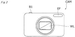
- FIG. 2 and FIG. 3 are schematic views illustrating another example of the optical device according to the present embodiment as an imaging device.
- FIG. 2 is a front view of an imaging device CAM
- FIG. 3 is a back view of the imaging device CAM.
- the imaging device CAM is a so-called digital still camera (a fixed lens camera), and a photographing lens WL (an optical system) includes an optical element including, as a base material, the optical glass according to the present embodiment.
- a shutter (not illustrated) of the photographing lens WL is opened, and light from an object to be imaged (a body) is converged by the photographing lens WL and an image is formed on imaging elements arranged on an image surface.
- An object image formed on the imaging elements is displayed on a liquid crystal monitor M arranged on the back of the imaging device CAM.
- a photographer decides composition of the object image while viewing the liquid crystal monitor M, and then presses down a release button B1 to capture the object image on the imaging elements.
- the object image is recorded and stored in a memory (not illustrated).
- An auxiliary light emitting unit EF that emits auxiliary light in a case that the object is dark and a function button B2 to be used for setting various conditions of the imaging device CAM and the like are arranged on the imaging device CAM.
- the optical glass according to the present embodiment is suitable as a member of such optical equipment.
- examples of the optical equipment to which the present embodiment is applicable include a projector and the like.
- examples of the optical element include a prism and the like.
- FIG. 4 is a block diagram illustrating an example of a configuration of a multi-photon microscope 2 according to the present embodiment.
- the multi-photon microscope 2 includes an objective lens 206, a condensing lens 208, and an image forming lens 210.
- At least one of the objective lens 206, the condensing lens 208, and the image forming lens 210 includes an optical element including, as a base material, the optical glass according to the present embodiment.
- description is mainly made on the optical system of the multi-photon microscope 2.
- a pulse laser device 201 emits ultrashort pulse light having, for example, a near-infrared wavelength (approximately 1000 nm) and a pulse width of a femtosecond unit (for example, 100 femtoseconds).
- ultrashort pulse light immediately after being emitted from the pulse laser device 201 is linearly polarized light that is polarized in a predetermined direction.
- a pulse division device 202 divides the ultrashort pulse light, increases a repetition frequency of the ultrashort pulse light, and emits the ultrashort pulse light.
- a beam adjustment unit 203 has a function of adjusting a beam diameter of the ultrashort pulse light, which enters from the pulse division device 202, to a pupil diameter of the objective lens 206, a function of adjusting convergence and divergence angles of the ultrashort pulse light in order to correct chromatic aberration (a focus difference) on an axis of a wavelength of light emitted from a sample S and the wavelength of the ultrashort pulse light, a pre-chirp function (group velocity dispersion compensation function) providing inverse group velocity dispersion to the ultrashort pulse light in order to correct the pulse width of the ultrashort pulse light, which is increased due to group velocity dispersion at the time of passing through the optical system, and the like.
- the ultrashort pulse light emitted from the pulse laser device 201 has a repetition frequency increased by the pulse division device 202, and is subjected to the above-mentioned adjustments by the beam adjustment unit 203.
- the ultrashort pulse light emitted from the beam adjustment unit 203 is reflected on a dichroic mirror 204 in a direction toward a dichroic mirror, passes through the dichroic mirror 205, and is converged by the objective lens 206, and the sample S is irradiated with the ultra short pulse light.
- an observation surface of the sample S may be scanned with the ultrashort pulse light through use of scanning means (not illustrated).
- a fluorescent pigment by which the sample S is dyed is subjected to multi-photon excitation in an irradiated region with the ultrashort pulse light and the vicinity thereof on the sample S, and fluorescence having a wavelength shorter than a near infrared wavelength of the ultrashort pulse light (hereinafter, also referred to "observation light”) is emitted.
- the observation light emitted from the sample S in a direction toward the objective lens 206 is collimated by the objective lens 206, and is reflected on the dichroic mirror 205 or passes through the dichroic mirror 205 depending on the wavelength.
- the observation light reflected on the dichroic mirror 205 enters a fluorescence detection unit 207.
- the fluorescence detection unit 207 includes a barrier filter, a photo multiplier tube (PMT), or the like.
- the fluorescence detection unit 207 receives the observation light reflected on the dichroic mirror 205 and outputs an electronic signal depending on an amount of the light.
- the fluorescence detection unit 207 detects the observation light over the observation surface of the sample S, in conformity with the ultrashort pulse light scanning on the observation surface of the sample S.
- all the observation light emitted from the sample S in a direction toward the objective lens 206 may be detected by the fluorescence detection unit 211 by excluding the dichroic mirror 205 from the optical path.
- the observation light is de-scanned by scanning means (not illustrated), passes through the dichroic mirror 204, is converged by the condensing lens 208, passes through a pinhole 209 provided at a position substantially conjugate to a focal position of the objective lens 206, passes through the image forming lens 210, and enters the fluorescence detection unit 211.
- the fluorescence detection unit 211 includes a barrier filter, a PMT, or the like.
- the fluorescence detection unit 211 receives, by the image forming lens 210, the observation light with which an image is formed on a light reception surface of the fluorescence detection unit 211 and outputs an electronic signal depending on an amount of the light.
- the fluorescence detection unit 211 detects the observation light over the observation surface of the sample S, in conformity with the ultrashort pulse light scanning on the observation surface of the sample S.
- the observation light emitted from the sample S in a direction opposite to the objective lens 206 is reflected on a dichroic mirror 212, and enters a fluorescence detection unit 213.
- the fluorescence detection unit 113 includes, for example, a barrier filter, a PMT, or the like.
- the fluorescence detection unit 113 receives the observation light reflected on the dichroic mirror 212 and outputs an electronic signal depending on an amount of the light.
- the fluorescence detection unit 213 detects the observation light over the observation surface of the sample S, in conformity with the ultrashort pulse light scanning on the observation surface of the sample S.
- the electronic signals output from the fluorescence detection units 207, 211, and 213 are input to, for example, a computer (not illustrated).
- the computer is capable of generating an observation image, displaying the generated observation image, and storing data on the observation image, based on the input electronic signals.
- FIG. 5 is a schematic view illustrating one example of a cemented lens according to the present embodiment.
- a cemented lens 3 is a compound lens including a first lens element 301 and a second lens element 302. As at least one of the first lens element and the second lens element, the optical glass according to the present embodiment is used. The first lens element and the second lens element are bonded to each other interposing therebetween a bonding member 303. A publicly-known adhesion or the like may be used as the bonding member 303. Note that, the "lens element” means each lens forming a single lens or a cemented lens.
- the cemented lens according to the present embodiment is advantageous, and can be used suitably as the optical element, the optical system, and the optical device that are described above, and the like.
- the optical system including the cemented lens can be suitably used particularly as the interchangeable camera lens, the optical device, and the like. Note that, in the aspect described above, description is made on the cemented lens using the two lens elements, but the aspect is not limited thereto.
- the cemented lens may include three or more lens elements. When the cemented lens includes three or more lens elements, it is sufficient that at least one of the three or more lens elements be formed by using the optical glass according to the present embodiment.
- the glass according to the present embodiment may also be used as a reflective element (retroreflector) 402 of a position measuring device 401 such as a laser tracker.
- a position measuring device 401 such as a laser tracker.
- an irradiation unit 403 that projects light onto the reflective element 402 and a light reception unit 404 that receives light reflected on the reflector are integrated with each other.
- the reflective element 402 can be attached to a part of a workpiece (measurement target object) 405 such as robot arms, machining equipment, and an airplane fuselage.
- the freely-selected number of reflective elements may be attached to the workpiece.
- the reflective element 402 may have a shape obtained by bonding hemispherical glass according to the present embodiment and hemispherical glass different from that of the present embodiment with each other, and is preferably cat's eye glass (spherical glass) .
- the position measuring device 401 orients the irradiation unit 403 in a direction toward the reflective element 402 provided to the workpiece 405, and emits measurement light. Subsequently, as illustrated in FIG. 6B , the light reception unit 404 receives the light reflected on the reflective element 402.
- the position measuring device 401 measures a distance to the reflective element 402, based on a time from timing at which the reflective element is irradiated with the light to timing at which the reflection light is received, and decides a three-dimensional position of the reflective element 402, based on the measured distance and the direction of the irradiation with the measurement light (an elevation angle and an azimuth angle).
- a distance measurement method there may be adopted a method of causing reference light being a reference and measurement light having been reflected on the reflective element 402 and returned to interfere with each other and obtaining a distance, based on a phase difference of the two types of light. Examples
- optical glasses in Examples and Comparative Example were produced by the following procedures. First, glass raw materials selected from oxides, hydroxides, phosphate compounds (phosphates, orthophosphoric acids, and the like), carbonates, nitrates, and the like were weighed so as to obtain the compositions (mass%) illustrated in each table. Next, the weighed raw materials were mixed and put in a platinum crucible, melted at a temperature of from 750 to 1100 degrees Celsius, and uniformed by stirring. After defoaming, the resultant was lowered to an appropriate temperature, poured in a mold, annealed, and molded. In this manner, each sample was obtained.
- glass raw materials selected from oxides, hydroxides, phosphate compounds (phosphates, orthophosphoric acids, and the like), carbonates, nitrates, and the like were weighed so as to obtain the compositions (mass%) illustrated in each table. Next, the weighed raw materials were mixed and put in a platinum crucible, melted at a temperature of from
- FIG. 7 is a graph in which P g, F and ⁇ d in each of Examples and Comparative Example are plotted.
- n d refractive index
- ⁇ d abbe number
- the partial dispersion ratio (P g, F ) in each of the samples indicates a ratio of partial dispersion (n g - n F ) to main dispersion (n F - n C ), and was obtained based on Expression (3) given below.
- n g indicates a refractive index of the glass with respect to light having a wavelength of 435.835 nm.
- the value of the partial dispersion ratio (P g, F ) was rounded to the third decimal place.
- P g , F n g ⁇ n F / n F ⁇ n C
- Abnormal dispersibility ( ⁇ P g, F ) in each of the samples indicates deviation from the partial dispersion ratio standard line based on the two types of glass F2 and K7 having normal dispersibilities.
- a difference in the vertical coordinate between a linear line connecting two difference types of glass and a value of the glass being a comparison target indicates deviation of the partial dispersion ratio, in other words, abnormal dispersibility ( ⁇ P g, F ).
- the abbe number ⁇ d and the partial dispersion ratio (P g, F ) of F2 and K7 are as follows.
- each table indicates compositions and physical properties in each example. Note that, a content rate of each component is expressed with mol% unless otherwise stated.
- optical glass was not obtained, and hence the physical properties thereof were "unmeasurable”.
- the optical glass of the present example had a refractive index of approximately 2 in the near-infrared range while having a high refractive index, high dispersion, and low abnormal dispersion.
Landscapes
- Physics & Mathematics (AREA)
- Chemical & Material Sciences (AREA)
- Optics & Photonics (AREA)
- General Physics & Mathematics (AREA)
- Chemical Kinetics & Catalysis (AREA)
- Geochemistry & Mineralogy (AREA)
- Materials Engineering (AREA)
- Organic Chemistry (AREA)
- General Chemical & Material Sciences (AREA)
- Life Sciences & Earth Sciences (AREA)
- Engineering & Computer Science (AREA)
- Analytical Chemistry (AREA)
- Glass Compositions (AREA)
Applications Claiming Priority (2)
| Application Number | Priority Date | Filing Date | Title |
|---|---|---|---|
| JP2022053320 | 2022-03-29 | ||
| PCT/JP2023/006625 WO2023189051A1 (ja) | 2022-03-29 | 2023-02-24 | 光学ガラス、光学素子、カメラ用交換レンズ、顕微鏡用対物レンズ、接合レンズ、光学系、光学装置、反射素子、位置測定装置 |
Publications (2)
| Publication Number | Publication Date |
|---|---|
| EP4501874A1 true EP4501874A1 (de) | 2025-02-05 |
| EP4501874A4 EP4501874A4 (de) | 2026-04-29 |
Family
ID=88200543
Family Applications (1)
| Application Number | Title | Priority Date | Filing Date |
|---|---|---|---|
| EP23779081.1A Pending EP4501874A4 (de) | 2022-03-29 | 2023-02-24 | Optisches glas, optisches element, wechselobjektiv für eine kamera, objektiv, sinterobjektiv, optisches system, spiegelelement und positionsmesseinrichtung |
Country Status (5)
| Country | Link |
|---|---|
| US (1) | US20250013028A1 (de) |
| EP (1) | EP4501874A4 (de) |
| JP (1) | JPWO2023189051A1 (de) |
| CN (1) | CN119032068A (de) |
| WO (1) | WO2023189051A1 (de) |
Family Cites Families (13)
| Publication number | Priority date | Publication date | Assignee | Title |
|---|---|---|---|---|
| JPS61197443A (ja) * | 1985-02-22 | 1986-09-01 | Hoya Corp | 光学ガラス |
| JP2004043294A (ja) * | 2002-05-22 | 2004-02-12 | Asahi Glass Co Ltd | 光学ガラスおよびレンズ |
| JPWO2006001346A1 (ja) * | 2004-06-24 | 2008-04-17 | 旭硝子株式会社 | 光学ガラスおよびレンズ |
| JP2010105906A (ja) * | 2008-09-30 | 2010-05-13 | Ohara Inc | 光学ガラス、光学素子及び精密プレス成形用プリフォーム |
| JP5823859B2 (ja) * | 2009-04-28 | 2015-11-25 | 株式会社オハラ | 光学ガラス、光学素子及び精密プレス成形用プリフォーム |
| WO2010126096A1 (ja) * | 2009-04-30 | 2010-11-04 | 株式会社オハラ | 光学ガラス |
| KR20110047979A (ko) * | 2009-10-30 | 2011-05-09 | 가부시키가이샤 오하라 | 광학 유리, 광학 소자 및 정밀 프레스 성형용 프리폼 |
| JP2011093755A (ja) * | 2009-10-30 | 2011-05-12 | Ohara Inc | 光学ガラス、光学素子及び精密プレス成形用プリフォーム |
| JP5850386B2 (ja) * | 2011-05-11 | 2016-02-03 | 日本電気硝子株式会社 | 光学ガラス |
| JP5831844B2 (ja) * | 2011-12-08 | 2015-12-09 | 日本電気硝子株式会社 | 光学ガラス |
| JP6701544B2 (ja) * | 2014-08-11 | 2020-05-27 | 日本電気硝子株式会社 | 赤外線透過ガラス |
| KR102506152B1 (ko) * | 2020-04-27 | 2023-03-06 | 한국광기술원 | 중적외광 투과 유리용 조성물 및 그의 제조방법 |
| JP7444749B2 (ja) | 2020-09-24 | 2024-03-06 | サンデン株式会社 | 車両用空調装置 |
-
2023
- 2023-02-24 WO PCT/JP2023/006625 patent/WO2023189051A1/ja not_active Ceased
- 2023-02-24 CN CN202380028001.4A patent/CN119032068A/zh active Pending
- 2023-02-24 EP EP23779081.1A patent/EP4501874A4/de active Pending
- 2023-02-24 JP JP2024511468A patent/JPWO2023189051A1/ja active Pending
-
2024
- 2024-09-25 US US18/895,958 patent/US20250013028A1/en active Pending
Also Published As
| Publication number | Publication date |
|---|---|
| US20250013028A1 (en) | 2025-01-09 |
| EP4501874A4 (de) | 2026-04-29 |
| CN119032068A (zh) | 2024-11-26 |
| WO2023189051A1 (ja) | 2023-10-05 |
| JPWO2023189051A1 (de) | 2023-10-05 |
Similar Documents
| Publication | Publication Date | Title |
|---|---|---|
| US12234183B2 (en) | Optical glass, and optical element, cemented lens, optical system, interchangeable lens for camera and optical device using same | |
| US20200115271A1 (en) | Optical glass, and optical element, optical system, cemented lens, interchangeable camera lens, and optical device using same | |
| US20240116798A1 (en) | Optical glass, optical element, optical system, cemented lens, interchangeable camera lens, microscope objective lens, and optical device | |
| US20210403371A1 (en) | Optical glass, optical element, optical system, interchangeable lens, and optical device | |
| JP7783316B2 (ja) | 光学ガラス、光学素子、光学系、交換レンズ及び光学装置 | |
| US20220162112A1 (en) | Optical glass, optical element, optical system, interchangeable lens, and optical device | |
| US20230331623A1 (en) | Optical glass, optical element, optical system, cemented lens, interchangeable lens for camera, objective lens for microscope, and optical device | |
| US20230278914A1 (en) | Optical glass, optical element, optical system, cemented lens, interchangeable lens for camera, objective lens for microscope, and optical device | |
| EP4501874A1 (de) | Optisches glas, optisches element, wechselobjektiv für eine kamera, objektiv, sinterobjektiv, optisches system, spiegelelement und positionsmesseinrichtung | |
| US20220227660A1 (en) | Optical glass, optical element, optical system, interchangeable lens, and optical device | |
| JP2021054693A (ja) | 光学ガラス、光学ガラスを用いた光学素子、光学系、交換レンズ、光学装置、及び光学ガラスの製造方法 | |
| US20240101465A1 (en) | Optical glass, optical element, optical system, cemented lens, interchangeable camera lens, microscope objective lens, and optical device | |
| JP7325253B2 (ja) | 光学ガラス、光学素子、光学系、交換レンズ及び光学装置 | |
| EP3385233A1 (de) | Optisches glas, optisches element mit dem optischen glas und optische vorrichtung | |
| JP2023104597A (ja) | 光学ガラス、光学素子、カメラ用交換レンズ、顕微鏡用対物レンズ、接合レンズ、光学系、及び光学装置 |
Legal Events
| Date | Code | Title | Description |
|---|---|---|---|
| STAA | Information on the status of an ep patent application or granted ep patent |
Free format text: STATUS: THE INTERNATIONAL PUBLICATION HAS BEEN MADE |
|
| PUAI | Public reference made under article 153(3) epc to a published international application that has entered the european phase |
Free format text: ORIGINAL CODE: 0009012 |
|
| STAA | Information on the status of an ep patent application or granted ep patent |
Free format text: STATUS: REQUEST FOR EXAMINATION WAS MADE |
|
| 17P | Request for examination filed |
Effective date: 20240926 |
|
| AK | Designated contracting states |
Kind code of ref document: A1 Designated state(s): AL AT BE BG CH CY CZ DE DK EE ES FI FR GB GR HR HU IE IS IT LI LT LU LV MC ME MK MT NL NO PL PT RO RS SE SI SK SM TR |
|
| DAV | Request for validation of the european patent (deleted) | ||
| DAX | Request for extension of the european patent (deleted) | ||
| A4 | Supplementary search report drawn up and despatched |
Effective date: 20260327 |
|
| RIC1 | Information provided on ipc code assigned before grant |
Ipc: C03C 3/14 20060101AFI20260323BHEP Ipc: C03C 3/12 20060101ALI20260323BHEP Ipc: C03C 3/145 20060101ALI20260323BHEP Ipc: C03C 3/15 20060101ALI20260323BHEP Ipc: C03C 3/155 20060101ALI20260323BHEP Ipc: G02B 1/00 20060101ALI20260323BHEP |