EP4502116A1 - Schmierfett - Google Patents
Schmierfett Download PDFInfo
- Publication number
- EP4502116A1 EP4502116A1 EP22933544.3A EP22933544A EP4502116A1 EP 4502116 A1 EP4502116 A1 EP 4502116A1 EP 22933544 A EP22933544 A EP 22933544A EP 4502116 A1 EP4502116 A1 EP 4502116A1
- Authority
- EP
- European Patent Office
- Prior art keywords
- rack
- grease
- shaft
- housing
- pinion
- Prior art date
- Legal status (The legal status is an assumption and is not a legal conclusion. Google has not performed a legal analysis and makes no representation as to the accuracy of the status listed.)
- Withdrawn
Links
Images


Classifications
-
- C—CHEMISTRY; METALLURGY
- C10—PETROLEUM, GAS OR COKE INDUSTRIES; TECHNICAL GASES CONTAINING CARBON MONOXIDE; FUELS; LUBRICANTS; PEAT
- C10M—LUBRICATING COMPOSITIONS; USE OF CHEMICAL SUBSTANCES EITHER ALONE OR AS LUBRICATING INGREDIENTS IN A LUBRICATING COMPOSITION
- C10M169/00—Lubricating compositions characterised by containing as components a mixture of at least two types of ingredient selected from base-materials, thickeners or additives, covered by the preceding groups, each of these compounds being essential
- C10M169/02—Mixtures of base-materials and thickeners
-
- C—CHEMISTRY; METALLURGY
- C10—PETROLEUM, GAS OR COKE INDUSTRIES; TECHNICAL GASES CONTAINING CARBON MONOXIDE; FUELS; LUBRICANTS; PEAT
- C10M—LUBRICATING COMPOSITIONS; USE OF CHEMICAL SUBSTANCES EITHER ALONE OR AS LUBRICATING INGREDIENTS IN A LUBRICATING COMPOSITION
- C10M107/00—Lubricating compositions characterised by the base-material being a macromolecular compound
- C10M107/02—Hydrocarbon polymers; Hydrocarbon polymers modified by oxidation
- C10M107/10—Hydrocarbon polymers; Hydrocarbon polymers modified by oxidation containing aliphatic monomer having more than 4 carbon atoms
-
- C—CHEMISTRY; METALLURGY
- C10—PETROLEUM, GAS OR COKE INDUSTRIES; TECHNICAL GASES CONTAINING CARBON MONOXIDE; FUELS; LUBRICANTS; PEAT
- C10M—LUBRICATING COMPOSITIONS; USE OF CHEMICAL SUBSTANCES EITHER ALONE OR AS LUBRICATING INGREDIENTS IN A LUBRICATING COMPOSITION
- C10M117/00—Lubricating compositions characterised by the thickener being a non-macromolecular carboxylic acid or salt thereof
- C10M117/02—Lubricating compositions characterised by the thickener being a non-macromolecular carboxylic acid or salt thereof having only one carboxyl group bound to an acyclic carbon atom, cycloaliphatic carbon atom or hydrogen
-
- C—CHEMISTRY; METALLURGY
- C10—PETROLEUM, GAS OR COKE INDUSTRIES; TECHNICAL GASES CONTAINING CARBON MONOXIDE; FUELS; LUBRICANTS; PEAT
- C10M—LUBRICATING COMPOSITIONS; USE OF CHEMICAL SUBSTANCES EITHER ALONE OR AS LUBRICATING INGREDIENTS IN A LUBRICATING COMPOSITION
- C10M2205/00—Organic macromolecular hydrocarbon compounds or fractions, whether or not modified by oxidation as ingredients in lubricant compositions
- C10M2205/02—Organic macromolecular hydrocarbon compounds or fractions, whether or not modified by oxidation as ingredients in lubricant compositions containing acyclic monomers
- C10M2205/0206—Organic macromolecular hydrocarbon compounds or fractions, whether or not modified by oxidation as ingredients in lubricant compositions containing acyclic monomers used as base material
-
- C—CHEMISTRY; METALLURGY
- C10—PETROLEUM, GAS OR COKE INDUSTRIES; TECHNICAL GASES CONTAINING CARBON MONOXIDE; FUELS; LUBRICANTS; PEAT
- C10M—LUBRICATING COMPOSITIONS; USE OF CHEMICAL SUBSTANCES EITHER ALONE OR AS LUBRICATING INGREDIENTS IN A LUBRICATING COMPOSITION
- C10M2205/00—Organic macromolecular hydrocarbon compounds or fractions, whether or not modified by oxidation as ingredients in lubricant compositions
- C10M2205/02—Organic macromolecular hydrocarbon compounds or fractions, whether or not modified by oxidation as ingredients in lubricant compositions containing acyclic monomers
- C10M2205/028—Organic macromolecular hydrocarbon compounds or fractions, whether or not modified by oxidation as ingredients in lubricant compositions containing acyclic monomers containing aliphatic monomers having more than four carbon atoms
- C10M2205/0285—Organic macromolecular hydrocarbon compounds or fractions, whether or not modified by oxidation as ingredients in lubricant compositions containing acyclic monomers containing aliphatic monomers having more than four carbon atoms used as base material
-
- C—CHEMISTRY; METALLURGY
- C10—PETROLEUM, GAS OR COKE INDUSTRIES; TECHNICAL GASES CONTAINING CARBON MONOXIDE; FUELS; LUBRICANTS; PEAT
- C10M—LUBRICATING COMPOSITIONS; USE OF CHEMICAL SUBSTANCES EITHER ALONE OR AS LUBRICATING INGREDIENTS IN A LUBRICATING COMPOSITION
- C10M2207/00—Organic non-macromolecular hydrocarbon compounds containing hydrogen, carbon and oxygen as ingredients in lubricant compositions
- C10M2207/10—Carboxylix acids; Neutral salts thereof
- C10M2207/12—Carboxylix acids; Neutral salts thereof having carboxyl groups bound to acyclic or cycloaliphatic carbon atoms
- C10M2207/125—Carboxylix acids; Neutral salts thereof having carboxyl groups bound to acyclic or cycloaliphatic carbon atoms having hydrocarbon chains of eight up to twenty-nine carbon atoms, i.e. fatty acids
- C10M2207/1256—Carboxylix acids; Neutral salts thereof having carboxyl groups bound to acyclic or cycloaliphatic carbon atoms having hydrocarbon chains of eight up to twenty-nine carbon atoms, i.e. fatty acids used as thickening agent
-
- C—CHEMISTRY; METALLURGY
- C10—PETROLEUM, GAS OR COKE INDUSTRIES; TECHNICAL GASES CONTAINING CARBON MONOXIDE; FUELS; LUBRICANTS; PEAT
- C10M—LUBRICATING COMPOSITIONS; USE OF CHEMICAL SUBSTANCES EITHER ALONE OR AS LUBRICATING INGREDIENTS IN A LUBRICATING COMPOSITION
- C10M2207/00—Organic non-macromolecular hydrocarbon compounds containing hydrogen, carbon and oxygen as ingredients in lubricant compositions
- C10M2207/10—Carboxylix acids; Neutral salts thereof
- C10M2207/12—Carboxylix acids; Neutral salts thereof having carboxyl groups bound to acyclic or cycloaliphatic carbon atoms
- C10M2207/125—Carboxylix acids; Neutral salts thereof having carboxyl groups bound to acyclic or cycloaliphatic carbon atoms having hydrocarbon chains of eight up to twenty-nine carbon atoms, i.e. fatty acids
- C10M2207/126—Carboxylix acids; Neutral salts thereof having carboxyl groups bound to acyclic or cycloaliphatic carbon atoms having hydrocarbon chains of eight up to twenty-nine carbon atoms, i.e. fatty acids monocarboxylic
- C10M2207/1265—Carboxylix acids; Neutral salts thereof having carboxyl groups bound to acyclic or cycloaliphatic carbon atoms having hydrocarbon chains of eight up to twenty-nine carbon atoms, i.e. fatty acids monocarboxylic used as thickening agent
-
- C—CHEMISTRY; METALLURGY
- C10—PETROLEUM, GAS OR COKE INDUSTRIES; TECHNICAL GASES CONTAINING CARBON MONOXIDE; FUELS; LUBRICANTS; PEAT
- C10M—LUBRICATING COMPOSITIONS; USE OF CHEMICAL SUBSTANCES EITHER ALONE OR AS LUBRICATING INGREDIENTS IN A LUBRICATING COMPOSITION
- C10M2207/00—Organic non-macromolecular hydrocarbon compounds containing hydrogen, carbon and oxygen as ingredients in lubricant compositions
- C10M2207/10—Carboxylix acids; Neutral salts thereof
- C10M2207/12—Carboxylix acids; Neutral salts thereof having carboxyl groups bound to acyclic or cycloaliphatic carbon atoms
- C10M2207/125—Carboxylix acids; Neutral salts thereof having carboxyl groups bound to acyclic or cycloaliphatic carbon atoms having hydrocarbon chains of eight up to twenty-nine carbon atoms, i.e. fatty acids
- C10M2207/127—Carboxylix acids; Neutral salts thereof having carboxyl groups bound to acyclic or cycloaliphatic carbon atoms having hydrocarbon chains of eight up to twenty-nine carbon atoms, i.e. fatty acids polycarboxylic
- C10M2207/1276—Carboxylix acids; Neutral salts thereof having carboxyl groups bound to acyclic or cycloaliphatic carbon atoms having hydrocarbon chains of eight up to twenty-nine carbon atoms, i.e. fatty acids polycarboxylic used as thickening agent
-
- C—CHEMISTRY; METALLURGY
- C10—PETROLEUM, GAS OR COKE INDUSTRIES; TECHNICAL GASES CONTAINING CARBON MONOXIDE; FUELS; LUBRICANTS; PEAT
- C10M—LUBRICATING COMPOSITIONS; USE OF CHEMICAL SUBSTANCES EITHER ALONE OR AS LUBRICATING INGREDIENTS IN A LUBRICATING COMPOSITION
- C10M2207/00—Organic non-macromolecular hydrocarbon compounds containing hydrogen, carbon and oxygen as ingredients in lubricant compositions
- C10M2207/10—Carboxylix acids; Neutral salts thereof
- C10M2207/12—Carboxylix acids; Neutral salts thereof having carboxyl groups bound to acyclic or cycloaliphatic carbon atoms
- C10M2207/125—Carboxylix acids; Neutral salts thereof having carboxyl groups bound to acyclic or cycloaliphatic carbon atoms having hydrocarbon chains of eight up to twenty-nine carbon atoms, i.e. fatty acids
- C10M2207/128—Carboxylix acids; Neutral salts thereof having carboxyl groups bound to acyclic or cycloaliphatic carbon atoms having hydrocarbon chains of eight up to twenty-nine carbon atoms, i.e. fatty acids containing hydroxy groups; Ethers thereof
- C10M2207/1285—Carboxylix acids; Neutral salts thereof having carboxyl groups bound to acyclic or cycloaliphatic carbon atoms having hydrocarbon chains of eight up to twenty-nine carbon atoms, i.e. fatty acids containing hydroxy groups; Ethers thereof used as thickening agents
-
- C—CHEMISTRY; METALLURGY
- C10—PETROLEUM, GAS OR COKE INDUSTRIES; TECHNICAL GASES CONTAINING CARBON MONOXIDE; FUELS; LUBRICANTS; PEAT
- C10M—LUBRICATING COMPOSITIONS; USE OF CHEMICAL SUBSTANCES EITHER ALONE OR AS LUBRICATING INGREDIENTS IN A LUBRICATING COMPOSITION
- C10M2227/00—Organic non-macromolecular compounds containing atoms of elements not provided for in groups C10M2203/00, C10M2207/00, C10M2211/00, C10M2215/00, C10M2219/00 or C10M2223/00 as ingredients in lubricant compositions
- C10M2227/06—Organic compounds derived from inorganic acids or metal salts
-
- C—CHEMISTRY; METALLURGY
- C10—PETROLEUM, GAS OR COKE INDUSTRIES; TECHNICAL GASES CONTAINING CARBON MONOXIDE; FUELS; LUBRICANTS; PEAT
- C10N—INDEXING SCHEME ASSOCIATED WITH SUBCLASS C10M RELATING TO LUBRICATING COMPOSITIONS
- C10N2010/00—Metal present as such or in compounds
- C10N2010/02—Groups 1 or 11
-
- C—CHEMISTRY; METALLURGY
- C10—PETROLEUM, GAS OR COKE INDUSTRIES; TECHNICAL GASES CONTAINING CARBON MONOXIDE; FUELS; LUBRICANTS; PEAT
- C10N—INDEXING SCHEME ASSOCIATED WITH SUBCLASS C10M RELATING TO LUBRICATING COMPOSITIONS
- C10N2020/00—Specified physical or chemical properties or characteristics, i.e. function, of component of lubricating compositions
- C10N2020/01—Physico-chemical properties
- C10N2020/02—Viscosity; Viscosity index
-
- C—CHEMISTRY; METALLURGY
- C10—PETROLEUM, GAS OR COKE INDUSTRIES; TECHNICAL GASES CONTAINING CARBON MONOXIDE; FUELS; LUBRICANTS; PEAT
- C10N—INDEXING SCHEME ASSOCIATED WITH SUBCLASS C10M RELATING TO LUBRICATING COMPOSITIONS
- C10N2030/00—Specified physical or chemical properties which is improved by the additive characterising the lubricating composition, e.g. multifunctional additives
- C10N2030/02—Pour-point; Viscosity index
-
- C—CHEMISTRY; METALLURGY
- C10—PETROLEUM, GAS OR COKE INDUSTRIES; TECHNICAL GASES CONTAINING CARBON MONOXIDE; FUELS; LUBRICANTS; PEAT
- C10N—INDEXING SCHEME ASSOCIATED WITH SUBCLASS C10M RELATING TO LUBRICATING COMPOSITIONS
- C10N2030/00—Specified physical or chemical properties which is improved by the additive characterising the lubricating composition, e.g. multifunctional additives
- C10N2030/06—Oiliness; Film-strength; Anti-wear; Resistance to extreme pressure
-
- C—CHEMISTRY; METALLURGY
- C10—PETROLEUM, GAS OR COKE INDUSTRIES; TECHNICAL GASES CONTAINING CARBON MONOXIDE; FUELS; LUBRICANTS; PEAT
- C10N—INDEXING SCHEME ASSOCIATED WITH SUBCLASS C10M RELATING TO LUBRICATING COMPOSITIONS
- C10N2040/00—Specified use or application for which the lubricating composition is intended
- C10N2040/04—Oil-bath; Gear-boxes; Automatic transmissions; Traction drives
-
- C—CHEMISTRY; METALLURGY
- C10—PETROLEUM, GAS OR COKE INDUSTRIES; TECHNICAL GASES CONTAINING CARBON MONOXIDE; FUELS; LUBRICANTS; PEAT
- C10N—INDEXING SCHEME ASSOCIATED WITH SUBCLASS C10M RELATING TO LUBRICATING COMPOSITIONS
- C10N2050/00—Form in which the lubricant is applied to the material being lubricated
- C10N2050/10—Form in which the lubricant is applied to the material being lubricated semi-solid; greasy
Definitions
- the present disclosure relates to a grease.
- a rack and pinion that is one type of gear is used, for example, in an electric power steering system, and includes a rack shaft having rack teeth and a pinion shaft having pinion teeth.
- a rack shaft having rack teeth and a pinion shaft having pinion teeth In the rack and pinion of the electric power steering system, it has been proposed to suppress wear of the rack teeth and the pinion teeth by grease lubrication (e.g., Patent Document 1).
- Patent Document 1 Japanese Unexamined Patent Application Publication No. 2006-335102 ( JP 2006-335102 A )
- a grease according to one aspect of the present disclosure includes a base oil and a thickener.
- the grease of the present disclosure has such characteristics that the grease can satisfactorily adhere to lubricated members at room temperature, can easily remain in a contact portion between the lubricated members, and can easily flow when the temperature rises due to sliding. Therefore, the grease can satisfactorily lubricate even lubricated members such as gears that have a wide contact portion and great slippage. Thus, wear of the contact portion between the lubricated members can be suppressed.
- the base oil is poly- ⁇ -olefin.
- the thickener is a soap.
- a viscous transition stress at 25°C is 300 Pa or more, and a viscous transition stress at 100°C is 40 Pa or less.
- a shear viscosity at 25°C and at a shear rate of 0.1 s -1 is 1.6 ⁇ 10 6 mPa ⁇ s or more, and a shear viscosity at 100°C and at a shear rate of 10 s -1 is 1.1 ⁇ 10 4 mPa ⁇ s or less.
- the viscous transition stress and the shear viscosity at 25°C are within the above ranges. Therefore, the grease has excellent adhesion to a contact portion between lubricated members at room temperature.
- the viscous transition stress and the shear viscosity at 100°C are within the above ranges. Therefore, the grease can easily flow when heat is generated due to sliding. Thus, the amount of wear of the contact portion between the lubricated members can be reduced.
- the soap be a calcium complex soap
- a mass of the calcium complex soap with respect to a total of the mass of the calcium complex soap and a mass of the poly- ⁇ -olefin be 5 to 15 mass%.
- the soap be lithium stearate, and the poly- ⁇ -olefin have a kinematic viscosity of 3 to 33 mm 2 /s at 40°C.
- a mass of the lithium stearate with respect to a total of the mass of the lithium stearate and a mass of the poly- ⁇ -olefin be 10 to 20 mass%.
- the grease of the present disclosure is suitable for use in lubrication of gears etc. that have a wide contact portion and great slippage. Specifically, the grease is suitable for use in, for example, lubrication of a rack and pinion provided in a steering gear device.
- a steering gear device using the grease of the present disclosure will be described first, followed by description of embodiments relating to the grease of the present disclosure.
- the grease of the present disclosure is used in, for example, dual-pinion type electric power steering systems and column type electric power steering systems.
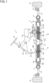
- FIG. 1 is a configuration diagram schematically illustrating an example of a dual-pinion type electric power steering system 1 including a steering gear device 3.
- FIG. 2 is a sectional view taken along A-A in FIG. 1 , illustrating part of the steering gear device 3.
- a lower side of the drawing corresponds to a lower side in a vertical direction when installed in a vehicle.
- FIG. 3 is a sectional view taken along B-B in FIG. 1 , illustrating part of the steering gear device 3.
- a lower side of the drawing corresponds to the lower side in the vertical direction when installed in the vehicle.
- the dual-pinion type electric power steering system 1 includes a steering wheel 10, a steering shaft 2, a first pinion shaft 32, a rack shaft 31, a housing 33, two rack bushings 30 and 34, two bearings 35 and 36, a first rack guide mechanism 39, and a steering assistance device 5.
- the steering assistance device 5 includes a controller 50, a torque sensor 51, an electric motor 52, a speed reducing mechanism 53, a second pinion shaft 54, two bearings 55 and 56, a worm housing 57, and a second rack guide mechanism 59.
- the speed reducing mechanism 53 includes a worm 531 and a worm wheel 532.
- a driver who drives an automobile including the dual-pinion type electric power steering system 1 performs steering operations by turning the steering wheel 10.
- the steering shaft 2 includes a column shaft 21, a first universal joint 23, an intermediate shaft 22, and a second universal joint 24.
- the first universal joint 23 includes a first yoke that is omitted from illustration, a plurality of first rolling elements that is omitted from illustration, a first joint spider that is omitted from illustration, a plurality of second rolling elements that is omitted from illustration, and a second yoke that is omitted from illustration.
- the second universal joint 24 includes a third yoke that is omitted from illustration, a plurality of third rolling elements that is omitted from illustration, a second joint spider that is omitted from illustration, a plurality of fourth rolling elements that is omitted from illustration, and a fourth yoke that is omitted from illustration.
- the column shaft 21 fixes the steering wheel 10 at one end thereof in an extending direction.
- the column shaft 21 fixes the first yoke of the first universal joint 23 at the other end thereof in the extending direction.
- the column shaft 21 is rotatable about a central axis in the extending direction.
- the first yoke is pivotably fitted to a first pair of trunnions located on the same central axis of the first joint spider via the plurality of first rolling elements.
- the second yoke is pivotably fitted to a second pair of trunnions located on the same central axis of the first joint spider via the plurality of second rolling elements.
- the central axes of the first pair of trunnions and the central axes of the second pair of trunnions intersect at an angle of 90 degrees.
- the second yoke of the first universal joint 23 fixes one end of the intermediate shaft 22 in the extending direction thereof.
- the intermediate shaft 22 fixes the third yoke of the second universal joint 24 at the other end thereof in the extending direction.
- the third yoke is pivotably fitted to a third pair of trunnions located on the same central axis of the second joint spider via the plurality of third rolling elements.
- the fourth yoke is pivotably fitted to a fourth pair of trunnions located on the same central axis of the second joint spider via the plurality of fourth rolling elements.
- the central axes of the third pair of trunnions and the central axes of the fourth pair of trunnions intersect at an angle of 90 degrees.
- the fourth yoke of the second universal joint 24 fixes one end of the first pinion shaft 32 in the extending direction thereof.
- the column shaft 21 turns about the central axis thereof in the extending direction thereof
- the intermediate shaft 22 also turns about a central axis thereof in the extending direction thereof
- the first pinion shaft 32 also turns about a central axis thereof in the extending direction thereof.
- the first pinion shaft 32, the rack shaft 31, the housing 33, the two rack bushings 30 and 34, the first bearing 35, the second bearing 36, the first rack guide mechanism 39, the electric motor 52, the speed reducing mechanism 53, the second pinion shaft 54, the third bearing 55, the fourth bearing 56, the worm housing 57, and the second rack guide mechanism 59 constitute the steering gear device 3 that serves as a rack and pinion type steering device.
- the housing 33 is represented by a hidden outline (long dashed double-short dashed lines), and inside thereof is illustrated.
- the first pinion shaft 32 extends from an upper side to a lower side of the automobile in the vertical direction.
- the first pinion shaft 32 includes, from one end side toward the other end in the extending direction thereof, a serrated portion 324, a first shaft portion 322, a first pinion toothed portion 320, and a first boss portion 323. Serrations are formed in the serrated portion 324.
- the fourth yoke of the second universal joint 24 is fixed to the serrations of the serrated portion 324.
- the first shaft portion 322 has a columnar shape.
- First pinion teeth 321 are formed over the entire face of the first pinion toothed portion 320 in the circumferential direction. An extending direction of the first pinion teeth 321 has an angle that is not 90 degrees with respect to the extending direction of the central axis of the first pinion shaft 32.
- the first boss portion 323 has a columnar shape.
- the housing 33 has a first opening 332 on the steering wheel 10 side, and a side opposite to the first opening 332 is sealed off.
- the first pinion shaft 32 is accommodated within the housing 33.
- the first pinion shaft 32 is supported by the two bearings 35 and 36 so as to be rotatable relative to the housing 33.
- the first bearing 35 is a ball bearing.
- the first bearing 35 includes an inner ring, an outer ring, and balls, with the inner ring being fixed to the first shaft portion 322 and also the outer ring being fixed to the housing 33, and the balls roll between the inner ring and the outer ring.
- the second bearing 36 is a roller bearing.
- the second bearing 36 includes rollers and an outer ring, with the outer ring being fixed to the housing 33, and the rollers roll between an outer peripheral face of the first boss portion 323 and the outer ring.
- a lid 37 through which the first pinion shaft 32 passes is fixed to the first opening 332 of the housing in a state in which the first pinion shaft 32, the first bearing 35, and the second bearing 36 are inserted into the housing 33.
- a seal is fixed to the lid 37, and the seal is slidable on an outer peripheral face 322b of the first shaft portion 322 of the first pinion shaft 32.
- a cover member 38 is further fixed to the housing 33. The cover member 38 covers part of the first shaft portion 322 of the first pinion shaft 32 from the outside in a radial direction.
- the rack shaft 31 includes, from one end toward the other end in an extending direction thereof, a first columnar portion 316, a first rack toothed portion 310, a second columnar portion 317, a second rack toothed portion 314, and a third columnar portion 318.
- the first rack toothed portion 310 has first rack teeth 311 formed on part thereof in the circumferential direction, and the other part thereof in the circumferential direction is a cylindrical face 312 having a central axis corresponding to the extending direction of the rack shaft 31.
- the second rack toothed portion 314 has second rack teeth 315 formed on part thereof in the circumferential direction, and the other part thereof in the circumferential direction is a cylindrical face 313 having a central axis corresponding to the extending direction of the rack shaft 31.
- An outer peripheral face of the first columnar portion 316, an outer peripheral face of the second columnar portion 317, and an outer peripheral face of the third columnar portion 318 are each a cylindrical face having a central axis corresponding to the extending direction of the rack shaft 31.
- the extending direction of the first rack teeth 311 has an angle that is not 90 degrees with respect to the extending direction of the rack shaft.
- the extending direction of the second rack teeth 315 has an angle that is not 90 degrees with respect to the extending direction of the rack shaft 31. Assuming that the angle of the first rack teeth 311 with respect to the extending direction of the rack shaft 31 is X, the angle of the second rack teeth 315 with respect to the extending direction of the rack shaft 31 is ⁇ -
- the housing 33 extends in a direction different from that of the first opening 332 on the steering wheel 10 side, and has a second opening 333 at one end in the extending direction and a third opening 334 at the other end in the extending direction.
- the rack shaft 31 is accommodated within the housing 33 along the extending direction of the housing 33.
- the first columnar portion 316 at one end of the rack shaft 31 in the extending direction thereof protrudes from the second opening 333 at one end of the housing 33 in the extending direction thereof.
- the third columnar portion 318 at the other end of the rack shaft 31 in the extending direction thereof protrudes from the third opening 334 at the other end of the housing 33 in the extending direction thereof.
- the housing 33 has a fourth opening 335.
- the fourth opening 335 is located closer to the other end of the housing in the extending direction than the first opening 332 is.
- the housing 33 further has a fifth opening 336 and a sixth opening 337.
- the fifth opening 336 is located at approximately the same position as that of the first opening 332 in the extending direction of the housing 33 to extend in a radial direction about a central axis corresponding to the extending direction of the housing 33, that is, in a direction perpendicular to the first opening 332.
- the sixth opening 337 is located at approximately the same position as that of the fourth opening 335 in the extending direction of the housing 33 to extend in a radial direction about a central axis corresponding to the extending direction of the housing 33, that is, in a direction perpendicular to the fourth opening 335.
- the first rack bushing 30 is fixed to one end of the housing 33 in the extending direction.
- the first rack bushing 30 is fixed to the housing 33 to adjoin the second opening 333.
- the first rack bushing 30 is slidable on the outer peripheral face of the first columnar portion 316 of the rack shaft 31.
- the second rack bushing 34 is fixed to the other end of the housing 33 in the extending direction.
- the second rack bushing 34 is fixed to the housing 33 to adjoin the third opening 334.
- the second rack bushing 34 is slidable on the outer peripheral face of the third columnar portion 318 of the rack shaft 31.
- the first pinion teeth 321 formed on the first pinion toothed portion 320 of the first pinion shaft 32 and the first rack teeth 311 formed on the first rack toothed portion 310 of the rack shaft 31 are in contact with each other so as to be rolling-slidable via a grease G.
- the first pinion teeth 321 and the first rack teeth 311 mesh with each other via the grease G.
- the first rack guide mechanism 39 is fixed to the housing 33.
- the first rack guide mechanism 39 is fixed to the fifth opening 336.
- the fifth opening 336 is located on the cylindrical face 312 side that is the other part of the first rack toothed portion 310 of the rack shaft 31 in the circumferential direction at a position where the first pinion shaft 32 meshes with the rack shaft 31 in the extending direction of the housing 33.
- the first rack guide mechanism 39 includes a first support yoke 391, a first sheet member 392, a first coil spring 393, and a first plug 394.
- the first sheet member 392 is interposed between the cylindrical face 312 that is the other part of the first rack toothed portion 310 of the rack shaft 31 in the circumferential direction and the cylindrical face of the first support yoke 391.
- the first sheet member 392 is fixed to the first support yoke 391.
- the first sheet member 392 and the cylindrical face 312 that is the other part of the first rack toothed portion 310 of the rack shaft 31 in the circumferential direction are in contact with each other so as to be slidable via the grease G.
- the first sheet member 392 includes a metal layer of, for example, bronze and a resin layer of, for example, PTFE, and the resin layer is in contact with the cylindrical face 312 via the grease G.
- the first plug 394 is fixed to the fifth opening 336 of the housing 33.
- the first plug 394 is in contact with one end of the first coil spring 393.
- the first support yoke 391 is in contact with the other end of the first coil spring 393.
- the first coil spring 393 is shorter than a free length thereof in a state in which the first plug 394 is fixed to the fifth opening 336.
- the first sheet member 392 is pressed against the rack shaft 31 with respect to the housing 33.
- the second pinion shaft 54 extends from the upper side to the lower side of the automobile in the vertical direction.
- the second pinion shaft 54 includes, from one end side toward the other end along the extending direction thereof, a fitting portion 544, a second shaft portion 542, a second pinion toothed portion 540, and a second boss portion 543.
- the fitting portion 544 has a columnar shape.
- the second shaft portion 542 has a columnar shape.
- Second pinion teeth 541 are formed over the entire face of the second pinion toothed portion 540 in the circumferential direction.
- An extending direction of the second pinion teeth 541 has an angle that is not 90 degrees with respect to the extending direction of the central axis of the second pinion shaft 54.
- the second boss portion 543 has a columnar shape.
- the worm wheel 532 is fitted to the fitting portion 544.
- the worm 531 is fixed to an output shaft 521 of the electric motor 52.
- the electric motor 52 is fixed to the worm housing 57.
- the worm housing 57 has a seventh opening 571.
- the output shaft 521 of the electric motor 52 is disposed in internal space of the worm housing 57 via the seventh opening 571.
- the electric motor 52 is fixed to the worm housing 57 so as to close off the seventh opening 571 of the worm housing 57.
- the worm 531 is disposed in the internal space of the worm housing 57.
- the worm wheel 532 is disposed in the internal space of the worm housing 57.
- the worm housing 57 has an eighth opening 572 vertically upward, and an assembly of the second pinion shaft 54 and the worm wheel 532 is inserted into the internal space of the worm housing 57 from the eighth opening 572.
- the eighth opening is closed with a lid 58.
- the worm housing 57 has a ninth opening 573 on the opposite side from the eighth opening 572. Part of the second shaft portion 542 of the second pinion shaft 54, the second pinion toothed portion 540, and the second boss portion 543 protrude from the ninth opening 573 of the worm housing 57.
- the worm housing 57 is fixed to the housing 33.
- the ninth opening 573 of the worm housing 57 and the fourth opening 335 of the housing 33 communicate with each other to seal off the internal space from the external space.
- the third bearing 55 is a ball bearing.
- the bearing 55 includes an inner ring, an outer ring, and balls, with the inner ring being fixed to the second shaft portion 542 and also the outer ring being fixed to the worm housing 57, and the balls roll between the inner ring and the outer ring.
- the bearing 56 is a roller bearing.
- the bearing 56 includes rollers and an outer ring, with the outer ring being fixed to the housing 33, and the rollers roll between an outer peripheral face of the second boss portion 543 and the outer ring.
- the second pinion teeth 541 formed on the second pinion toothed portion 540 of the second pinion shaft 54 and the second rack teeth 315 formed on the second rack toothed portion 314 of the rack shaft 31 are in contact with each other so as to be rolling-slidable via the grease G.
- the second pinion teeth 541 and the second rack teeth 315 mesh with each other via the grease G.
- the second rack guide mechanism 59 is fixed to the housing 33.
- the second rack guide mechanism 59 is fixed to the sixth opening 337.
- the sixth opening 337 is located on the cylindrical face 313 side that is the other part of the second rack toothed portion 314 of the rack shaft 31 in the circumferential direction at a position where the second pinion shaft 54 meshes with the rack shaft 31 in the extending direction of the housing 33.
- the second rack guide mechanism 59 includes a second support yoke 591, a second sheet member 592, a second coil spring 593, and a second plug 594.
- the second sheet member 592 is interposed between the cylindrical face 313 that is the other part of the second rack toothed portion 314 of the rack shaft 31 in the circumferential direction and the cylindrical face of the second support yoke 591.
- the second sheet member 592 is fixed to the second support yoke 591.
- the second sheet member 592 and the cylindrical face 313 that is the other part of the second rack toothed portion 314 of the rack shaft 31 in the circumferential direction are in contact with each other so as to be slidable via the grease G.
- the second sheet member 592 includes a metal layer of, for example, bronze and a resin layer of, for example, PTFE, and the resin layer is in contact with the cylindrical face 313 via the grease G.
- the second plug 594 is fixed to the sixth opening 337 of the housing 33.
- the second plug 594 is in contact with one end of the second coil spring 593.
- the second support yoke 591 is in contact with the other end of the second coil spring 593.
- the second coil spring 593 is shorter than a free length thereof in a state in which the second plug 594 is fixed to the sixth opening 337.
- the second sheet member 592 is pressed against the rack shaft 31 with respect to the housing 33.
- the torque sensor 51 detects steering torque applied by the driver to the steering wheel 10 through the column shaft 21.
- the speed reducing mechanism 53 is an assembly in which the worm 531 that rotates together with the output shaft 521 of the electric motor 52 and the worm wheel 532 that rotates together with the second pinion shaft 54 mesh with each other.
- a motor current is supplied to the electric motor 52 from the controller 50.
- the controller 50 controls the electric motor 52 based on the steering torque detected by the torque sensor 51, vehicle speed, etc., and transmits, to the second pinion shaft 54, rotational force of the output shaft 521 of the electric motor 52 that is reduced in speed by the speed reducing mechanism 53.
- the rotational force of the second pinion shaft 54 is applied from the second pinion teeth 541 to the second rack teeth 315 as a steering assisting force.
- the housing 33 is fixed to the automobile that is omitted from illustration, with the extending direction of the housing 33 aligned with a vehicle-width direction.
- Ball joint sockets 11, 11 are fixed to one end and the other end of the rack shaft 31, respectively, and tie rods 12, 12 connected to the ball joint sockets 11, 11, respectively, are connected to bearing rings of rolling bearings that rotatably support a pair of right and left front wheels 14, 14 via knuckle arms 13, 13.
- the linear movement of the rack shaft 31 in the extending direction of the housing 33 steers the right and left front wheels 14, 14 that are steered wheels.
- the grease G is sealed within the housing 33.
- the grease G is applied between rolling and sliding faces of the first pinion teeth 321 and rolling and sliding faces of the first rack teeth 311 that are in contact with each other when the first pinion teeth 321 and the first rack teeth 311 mesh with each other, thereby lubricating both the rolling and sliding faces.
- the grease G is applied between a sliding face of the first sheet member 392 and a sliding face of the cylindrical face 312 that is the other part of the first rack toothed portion 310 of the rack shaft 31 in the circumferential direction, the sliding faces being in contact with each other when the first sheet member 392 and the rack shaft 31 are pressed against each other, thereby lubricating both the sliding faces.
- the grease G is applied between rolling and sliding faces of the second pinion teeth 541 and rolling and sliding faces of the second rack teeth 315 that are in contact with each other when the second pinion teeth 541 and the second rack teeth 315 mesh with each other, thereby lubricating both the rolling and sliding faces.
- the grease G is applied between a sliding face of the second sheet member 592 and a sliding face of the cylindrical face 313 that is the other part of the second rack toothed portion 314 of the rack shaft 31 in the circumferential direction, the sliding faces being in contact with each other when the second sheet member 592 and the rack shaft 31 are pressed against each other, thereby lubricating both the sliding faces.
- the grease of the present disclosure is sealed as the grease G within the steering gear device 3 configured in this way.
- the grease of the present disclosure can satisfactorily lubricate the meshing portion between the first pinion teeth 321 and the first rack teeth 311, the meshing portion between the second pinion teeth 541 and the second rack teeth 315, the sliding contact portion between the first sheet member 392 of the first rack guide mechanism 39 and the rack shaft 31, and the sliding contact portion between the second sheet member 592 of the second rack guide mechanism 59 and the rack shaft 31. Therefore, the amounts of wear in these portions can be reduced.
- FIG. 4 is a configuration diagram schematically illustrating an example of a column type electric power steering system 601 including a steering gear device 603.
- FIG. 5 is a sectional view taken along A-A in FIG. 4 , illustrating part of the steering gear device 603.
- a lower side of the drawing corresponds to the lower side in the vertical direction when installed in the vehicle.
- the column type electric power steering system 601 includes a steering wheel 610, a steering shaft 602, a pinion shaft 632, a rack shaft 631, a housing 633, two rack bushings 630 and 634, two bearings 635 and 636, a rack guide mechanism 639, and a steering assistance device 4.
- a driver who drives an automobile including the column type electric power steering system 601 performs steering operations by turning the steering wheel 610.
- the steering shaft 602 includes a column shaft 621, a first universal joint 623, an intermediate shaft 622, and a second universal joint 624.
- the first universal joint 623 includes a first yoke that is omitted from illustration, a plurality of first rolling elements that is omitted from illustration, a first joint spider that is omitted from illustration, a plurality of second rolling elements that is omitted from illustration, and a second yoke that is omitted from illustration.
- the second universal joint 624 includes a third yoke that is omitted from illustration, a plurality of third rolling elements that is omitted from illustration, a second joint spider that is omitted from illustration, a plurality of fourth rolling elements that is omitted from illustration, and a fourth yoke that is omitted from illustration.
- the column shaft 621 fixes the steering wheel 610 at one end thereof in the extending direction.
- the column shaft 621 fixes the first yoke of the first universal joint 623 at the other end thereof in the extending direction.
- the column shaft 621 is rotatable about a central axis in the extending direction.
- the first yoke is pivotably fitted to a first pair of trunnions located on the same central axis of the first joint spider via the plurality of first rolling elements.
- the second yoke is pivotably fitted to a second pair of trunnions located on the same central axis of the first joint spider via the plurality of second rolling elements.
- the central axes of the first pair of trunnions and the central axes of the second pair of trunnions intersect at an angle of 90 degrees.
- the second yoke of the first universal joint 623 fixes one end of the intermediate shaft 622 in the extending direction thereof.
- the intermediate shaft 622 fixes the third yoke of the second universal joint 624 at the other end thereof in the extending direction.
- the third yoke is pivotably fitted to a third pair of trunnions located on the same central axis of the second joint spider via the plurality of third rolling elements.
- the fourth yoke is pivotably fitted to a fourth pair of trunnions located on the same central axis of the second joint spider via the plurality of fourth rolling elements.
- the central axes of the third pair of trunnions and the central axes of the fourth pair of trunnions intersect at an angle of 90 degrees.
- the fourth yoke of the second universal joint 624 fixes one end of the pinion shaft 632 in the extending direction thereof.
- the column shaft 621 turns about the central axis thereof in the extending direction thereof
- the intermediate shaft 622 also turns about a central axis thereof in the extending direction thereof
- the pinion shaft 632 also turns about a central axis thereof in the extending direction thereof.
- the pinion shaft 632, the rack shaft 631, the housing 633, the two rack bushings 630 and 634, the two bearings 635 and 636, and the rack guide mechanism 639 constitute the steering gear device 603 that serves as a rack and pinion type steering device.
- the housing 633 is represented by a hidden outline (long dashed double-short dashed lines), and inside thereof is illustrated.
- the pinion shaft 632 extends from the upper side to the lower side of the automobile in the vertical direction.
- the pinion shaft 632 includes, from one end side toward the other end in the extending direction thereof, a serrated portion 724, a shaft portion 722, a pinion toothed portion 720, and a boss portion 723. Serrations are formed in the serrated portion 724.
- the fourth yoke of the second universal joint 624 is fixed to the serrations of the serrated portion 724.
- the shaft portion 722 has a columnar shape.
- Pinion teeth 721 are formed over the entire face of the pinion toothed portion 720 in the circumferential direction.
- An extending direction of the pinion teeth 721 has an angle that is not 90 degrees with respect to the extending direction of the central axis of the pinion shaft 632.
- the boss portion 723 has a columnar shape.
- the housing 633 has a first opening 732 on the steering wheel 610 side, and a side opposite to the first opening 732 is sealed off.
- the pinion shaft 632 is accommodated within the housing 633.
- the pinion shaft 632 is supported by the two bearings 635 and 636 so as to be rotatable relative to the housing 633.
- the bearing 635 is a ball bearing.
- the bearing 635 includes an inner ring, an outer ring, and balls, with the inner ring being fixed to the shaft portion 722 and also the outer ring being fixed to the housing 633, and the balls roll between the inner ring and the outer ring.
- the bearing 636 is a roller bearing.
- the bearing 636 includes rollers and an outer ring, with the outer ring being fixed to the housing 633, and the rollers roll between an outer peripheral face of the boss portion 723 and the outer ring.
- a lid 637 through which the pinion shaft 632 passes is fixed to the first opening 732 of the housing in a state in which the pinion shaft 632 and the two bearings 635 and 636 are inserted into the housing 633.
- a seal is fixed to the lid 637, and the seal is slidable on an outer peripheral face 722b of the shaft portion 722 of the pinion shaft 632.
- a cover member 638 is further fixed to the housing 633. The cover member 638 covers part of the shaft portion 722 of the pinion shaft 632 from the outside in the radial direction.
- the rack shaft 631 includes, from one end toward the other end in an extending direction thereof, a first columnar portion 716, a rack toothed portion 710, and a second columnar portion 717.
- the rack toothed portion 710 has rack teeth 711 formed on part thereof in the circumferential direction, and the other part thereof in the circumferential direction is a cylindrical face 712 having a central axis corresponding to the extending direction of the rack shaft 631.
- An outer peripheral face of the first columnar portion 716 and an outer peripheral face of the second columnar portion 717 are each a cylindrical face having a central axis corresponding to the extending direction of the rack shaft 631.
- the extending direction of the rack teeth 711 has an angle that is not 90 degrees with respect to the extending direction of the rack shaft 631.
- the housing 633 extends in a direction different from that of the first opening 732 on the steering wheel 610 side, and has a second opening 733 at one end in the extending direction and a third opening 734 at the other end in the extending direction.
- the rack shaft 631 is accommodated within the housing 633 along the extending direction of the housing 633.
- One end of the rack shaft 631 in the extending direction thereof protrudes from the second opening 733 at one end of the housing 633 in the extending direction thereof.
- the other end of the rack shaft 631 in the extending direction thereof protrudes from the third opening 734 at the other end of the housing 633 in the extending direction thereof.
- the first rack bushing 630 is fixed to one end of the housing 633 in the extending direction.
- the first rack bushing 630 is fixed to the housing 633 to adjoin the second opening 733.
- the first rack bushing 630 is slidable on the outer peripheral face of the first columnar portion 716 of the rack shaft 631.
- the second rack bushing 634 is fixed to the other end of the housing 633 in the extending direction.
- the second rack bushing 634 is fixed to the housing 633 to adjoin the third opening 734.
- the second rack bushing 634 is slidable on the outer peripheral face of the second columnar portion 717 of the rack shaft 631.
- the pinion teeth 721 formed on the pinion toothed portion 720 of the pinion shaft 632 and the rack teeth 711 formed on the rack toothed portion 710 of the rack shaft 631 are in contact with each other so as to be rolling-slidable via the grease G.
- the pinion teeth 721 and the rack teeth 711 mesh with each other via the grease G.
- the housing 633 is fixed to the automobile that is omitted from illustration, with the extending direction of the housing 633 aligned with a vehicle-width direction.
- Ball joint sockets 11, 11 are fixed to one end and the other end of the rack shaft 631, respectively, and tie rods 12, 12 connected to the ball joint sockets 11, 11, respectively, are connected to bearing rings of rolling bearings that rotatably support a pair of right and left front wheels 14, 14 via knuckle arms 13, 13.
- the linear movement of the rack shaft 631 in the extending direction of the housing 633 steers the right and left front wheels 14, 14 that are steered wheels.
- the rack guide mechanism 639 is fixed to the housing 633.
- the housing 633 has a fourth opening 736 located on the cylindrical face 712 side that is the other part of the rack toothed portion 710 of the rack shaft 631 in the circumferential direction at a position where the pinion shaft 632 meshes with the rack shaft 631 in the extending direction.
- the rack guide mechanism 639 includes a support yoke 791, a sheet member 792, a coil spring 793, and a plug 794.
- the sheet member 792 is interposed between the cylindrical face 712 that is the other part of the rack toothed portion 710 of the rack shaft 631 in the circumferential direction and the cylindrical face of the support yoke 791.
- the sheet member 792 is fixed to the support yoke 791.
- the sheet member 792 and the cylindrical face 712 that is the other part of the rack toothed portion 710 of the rack shaft 631 in the circumferential direction are in contact with each other so as to be slidable via the grease G.
- the sheet member 792 includes a metal layer of, for example, bronze and a resin layer of, for example, PTFE, and the resin layer is in contact with the cylindrical face 712 via the grease G.
- the plug 794 is fixed to the fourth opening 736 of the housing 633.
- the plug 794 is in contact with one end of the coil spring 793.
- the support yoke 791 is in contact with the other end of the coil spring 793.
- the coil spring 793 is shorter than a free length thereof in a state in which the plug 794 is fixed to the fourth opening 736.
- the sheet member 792 is pressed against the rack shaft 631 with respect to the housing 633.
- the steering assistance device 4 includes a controller 40, a torque sensor 41 that detects steering torque applied by the driver to the steering wheel 610, an electric motor 42, and a speed reducing mechanism 43 that reduces the speed of rotational force of an output shaft 421 of the electric motor 42 and transmits the rotational force to the column shaft 621.
- the speed reducing mechanism 43 is an assembly in which a worm 431 that rotates together with the output shaft 421 of the electric motor 42 and a worm wheel 432 that rotates together with the column shaft 621 mesh with each other. A motor current is supplied to the electric motor 42 from the controller 40.
- the controller 40 controls the electric motor 42 based on the steering torque detected by the torque sensor 41, vehicle speed, etc., and applies the rotational force of the output shaft 421 of the electric motor 42 that is reduced in speed by the speed reducing mechanism 43 to the column shaft 621 as a steering assisting force.
- the grease G is sealed within the housing 633.
- the grease G is applied between rolling and sliding faces of the pinion teeth 721 and rolling and sliding faces of the rack teeth 711 that are in contact with each other when the pinion teeth 721 and the rack teeth 711 mesh with each other, thereby lubricating both the rolling and sliding faces.
- the grease G is applied between a sliding face of the sheet member 792 and a sliding face of the cylindrical face 712 that is the other part of the rack toothed portion 710 of the rack shaft 631 in the circumferential direction, the sliding faces being in contact with each other when the sheet member 792 and the rack shaft 631 are pressed against each other, thereby lubricating both the sliding faces.
- the grease of the present disclosure is sealed as the grease G within the steering gear device 603 configured in this way.
- the grease of the present disclosure can satisfactorily lubricate the meshing portion between the pinion teeth 721 and the first rack teeth 711, and the sliding contact portion between the sheet member 792 of the rack guide mechanism 639 and the rack shaft 631. Therefore, the amounts of wear in these portions can be reduced.
- the grease of the present disclosure can be used by being sealed within the dual-pinion type electric power steering system, the column type electric power steering system, etc.
- a grease according to an embodiment of the present disclosure includes a base oil and a thickener.
- the viscous transition stress at 25°C is 300 Pa or more
- the shear viscosity at 25°C and at the shear rate of 0.1 s -1 is 1.6 ⁇ 10 6 mPa ⁇ s or more, thereby ensuring adhesion of the grease to a contact portion between lubricated members.
- the grease When the viscous transition stress at 25°C is less than 300 Pa, the grease does not easily remain in the contact portion between the lubricated members and is more likely to be expelled to portions other than the contact portion in a state in which the lubricated members are stationary or are vibrating or slightly sliding at room temperature.
- the shear viscosity at 25°C and at the shear rate of 0.1 s -1 is less than 1.6 ⁇ 10 6 mPa ⁇ s
- the grease may move to portions other than the contact portion between the lubricated members early at the start of movement of the grease due to the sliding of the lubricated members. Therefore, the lubrication performance decreases when the viscous transition stress and/or the shear viscosity at 25°C are/is outside the above ranges.
- the viscous transition stress at 25°C is preferably 1000 Pa or less.
- the shear viscosity at 25°C and at the shear rate of 0.1 s -1 is preferably 1.0 ⁇ 10 7 mPa ⁇ s or less.
- the viscous transition stress at 100°C is 40 Pa or less
- the shear viscosity at 100°C and at the shear rate of 10 s -1 is 1.1 ⁇ 10 4 mPa ⁇ s or less. Therefore, the grease easily flows into the contact portion between the lubricated members when the temperature of the lubricated members rises due to heat generated by sliding. Thus, the amount of wear of the contact portion between the lubricated members is reduced.
- the grease does not readily move to the contact portion between the lubricated members in the event of a temperature rise in the contact portion between the lubricated members due to the sliding of the lubricated members.
- the viscous transition stress at 100°C is preferably 10 Pa or more.
- the shear viscosity at 100°C and at the shear rate of 10 s -1 is preferably 1.0 ⁇ 10 3 mPa ⁇ s or more.
- the base oil is poly- ⁇ -olefin (PAO).
- poly- ⁇ -olefin examples include oligomerized or polymerized ⁇ -olefins such as 1-hexene, 1-octene, 1-nonene, 1-decene, 1-dodecene, and 1-tetradecene, and further hydrides thereof.
- the poly- ⁇ -olefin is preferably PAO2 to PAO10 that are oligomerized 1-decene.
- the base oil kinematic viscosity of the poly- ⁇ -olefin at 40°C is preferably 3 to 68 mm 2 /s.
- the thickener is a soap.
- Examples of the soap include a calcium soap, a calcium complex soap, a lithium soap, a lithium complex soap, a sodium soap, an aluminum soap, and an aluminum complex soap.
- the soap is preferably lithium stearate that is one kind of lithium soap, or the following mixture A that is one kind of calcium complex soap.
- a suitable composition of the base oil and the thickener is the following (a) or (b).
- the grease having the above composition (a) or (b) can easily be designed so that the shear viscosity and the viscous transition stress are within the above ranges. Therefore, the grease having the above composition (a) or (b) can easily remain in the contact portion between the lubricated members when it is used in a steering gear device etc. Thus, the grease is suitable for suppressing wear of rack teeth and pinion teeth.
- the grease may contain additives as long as the shear viscosity and the viscous transition stress do not deviate from the above ranges.
- the additives include antioxidants, rust inhibitors, extreme pressure additives, anti-wear agents, dyes, hue stabilizers, viscosity improvers, structural stabilizers, metal deactivators, and viscosity index improvers.
- the total content of the additives is preferably 15 mass% or less with respect to the total mass of the base oil and the thickener.
- the worked penetration of the grease is preferably No. 00 to No. 2. By adjusting the worked penetration within this range, it is possible to achieve both flowability to the contact portion between the lubricated members and resistance to grease softening due to shear.
- the grease of the present disclosure can suitably be used in the rack and pinion provided in the steering gear device of the automobile, etc.
- the grease can suitably be used for lubricating mechanical elements that undergo sliding, such as gears.
- the grease can also be used as a grease to be sealed within a rolling bearing etc.
- the above grease can be produced, for example, through a process of producing a soap by saponification in a base oil.
- the grease can be produced by, for example, the following method.
- a fatty acid such as stearic acid, 11-octadecenoic acid, or palmitic acid is added to poly- ⁇ -olefin, and the mixture is heated to a predetermined temperature.
- a base such as lithium hydroxide or calcium hydroxide is added to the poly- ⁇ -olefin solution, and the fatty acid and the base undergo a saponification reaction to produce a soap.
- the mixture is heated to a predetermined temperature (e.g., 200 to 230°C) to dissolve the soap in the poly- ⁇ -olefin.
- the poly- ⁇ -olefin solution is cooled to precipitate the soap, thereby obtaining a grease.
- additives may be mixed or the mixture may be kneaded to a predetermined cone penetration if necessary.
- the grease can also be produced by, for example, the following method as another method.
- a soap such as lithium stearate or calcium stearate that has separately been produced is added to poly- ⁇ -olefin, and the mixture is heated to a predetermined temperature (e.g., 200 to 230°C) with stirring to dissolve the soap in the poly- ⁇ -olefin. Then, the poly- ⁇ -olefin solution with the soap dissolved therein is cooled to precipitate the soap, thereby obtaining a grease. After the cooling, additives may be mixed or the mixture may be kneaded to a predetermined cone penetration if necessary.
- a predetermined temperature e.g. 200 to 230°C
- PAO401 (Durasyn 164 produced by INEOS Oligomers, kinematic viscosity at 40°C: 18 mm 2 /s) was poured at 770 g into a stainless steel beaker. Into the beaker, 133.2 g of stearic acid were added and heated with stirring. When the temperature of the solution reached 90°C, 11.2 g of lithium hydroxide dissolved in distilled water by heating were gradually added. After the entire amount of lithium hydroxide was added, the beaker was kept at 110°C for 120 minutes.
- the beaker was heated to 210°C at a rate of 2°C/min.
- the mixture was kneaded to a cone penetration No. 1 (310 to 340, median: 325) to obtain a grease.
- PAO801 (Durasyn 168 produced by INEOS Oligomers, kinematic viscosity at 40°C: 50 mm 2 /s) was poured at 770 g into a stainless steel beaker. Into this beaker, 56.9 g of stearic acid, 2.46 g of 11-octadecenoic acid, and 20.0 g of palmitic acid were added and heated with stirring. When the temperature of the solution reached 90°C, 5.5 g of calcium hydroxide dissolved in distilled water by heating were gradually added.
- the beaker was kept at 110°C for 120 minutes.
- the beaker was heated to 220°C at a rate of 2°C/min.
- the mixture was kneaded to a cone penetration No. 0.5 (325 to 355, median: 340) to obtain a grease.
- PAO601 (Durasyn 166 produced by INEOS Oligomers, kinematic viscosity at 40°C: 31 mm 2 /s) was poured at 770 g into a stainless steel beaker. Into the beaker, 142.2 g of 12OH-stearic acid were added and heated with stirring. When the temperature of the solution reached 90°C, 11.3 g of lithium hydroxide dissolved in distilled water by heating were gradually added.
- the beaker was kept at 110°C for 120 minutes.
- the beaker was heated to 200°C at a rate of 2°C/min. As soon as the temperature reached 200°C, the heating was stopped and the mixture was cooled to room temperature. The mixture was kneaded to a cone penetration No. 2 (265 to 295, median: 280) to obtain a grease.
- PAO10 (Durasyn 170 produced by INEOS Oligomers, kinematic viscosity at 40°C: 65 mm 2 /s) was poured at 770 g into a stainless steel beaker. Into the beaker, 82.0 g of 12OH-stearic acid were added and heated with stirring. When the temperature of the solution reached 90°C, 3.3 g of lithium hydroxide and 3.8 g of calcium hydroxide dissolved in distilled water by heating were gradually added.
- the beaker was kept at 110°C for 120 minutes. Then, the beaker was heated to 210°C at a rate of 2°C/min.
- the mixture was kneaded to a cone penetration No. 0.5 (325 to 355, median: 340) to obtain a grease.
- PAO801 (Durasyn 168 produced by INEOS Oligomers, kinematic viscosity at 40°C: 50 mm 2 /s) was poured at 770 g into a stainless steel beaker. Into the beaker, 189.7 g of stearic acid were added and heated with stirring. When the temperature of the solution reached 90°C, 16.0 g of lithium hydroxide dissolved in distilled water by heating were gradually added. After the entire amount of lithium hydroxide was added, the beaker was kept at 110°C for 120 minutes.
- the beaker was heated to 210°C at a rate of 2°C/min.
- the mixture was kneaded to a cone penetration No. 1 (310 to 340, median: 325) to obtain a grease.
- the worked penetration (60W) was measured by a method conforming to JIS K 2220.7.
- a viscoelasticity measuring device (“MCR301” manufactured by Anton Paar) was used to measure the shear viscosity of the grease.
- the grease was sealed at 1.4 g within a shielded deep groove ball bearing (6204ZZ) and the bearing was rotated for 20 hours at room temperature under the conditions conforming to ASTM D3336. Then, the presence or absence of grease leakage from a clearance between a side plate and an inner ring was visually checked. The results were evaluated according to the following criteria.
- the grease was applied to a flat plate made of SUJ2, a load was applied thereon so that the contact pressure was 2370 MPa, and a steel ball made of SUJ2 was brought into contact with the flat plate.
- the flat plate and the steel ball were kept in contact with each other at a sliding speed of 44 mm/s for 18 hours. Then, the wear mark diameter ( ⁇ m) of the steel ball was measured and defined as the amount of wear.
- the test temperature was 110°C.
Landscapes
- Chemical & Material Sciences (AREA)
- Chemical Kinetics & Catalysis (AREA)
- General Chemical & Material Sciences (AREA)
- Oil, Petroleum & Natural Gas (AREA)
- Organic Chemistry (AREA)
- Transmission Devices (AREA)
- Power Steering Mechanism (AREA)
Applications Claiming Priority (1)
| Application Number | Priority Date | Filing Date | Title |
|---|---|---|---|
| PCT/JP2022/014675 WO2023181407A1 (ja) | 2022-03-25 | 2022-03-25 | グリース |
Publications (2)
| Publication Number | Publication Date |
|---|---|
| EP4502116A1 true EP4502116A1 (de) | 2025-02-05 |
| EP4502116A4 EP4502116A4 (de) | 2025-05-07 |
Family
ID=88100322
Family Applications (1)
| Application Number | Title | Priority Date | Filing Date |
|---|---|---|---|
| EP22933544.3A Withdrawn EP4502116A4 (de) | 2022-03-25 | 2022-03-25 | Schmierfett |
Country Status (5)
| Country | Link |
|---|---|
| US (1) | US20250154428A1 (de) |
| EP (1) | EP4502116A4 (de) |
| JP (1) | JPWO2023181407A1 (de) |
| CN (1) | CN118786203A (de) |
| WO (1) | WO2023181407A1 (de) |
Family Cites Families (12)
| Publication number | Priority date | Publication date | Assignee | Title |
|---|---|---|---|---|
| JP2006335102A (ja) * | 2005-05-31 | 2006-12-14 | Nsk Ltd | 電動パワーステアリング装置 |
| JP2013023644A (ja) * | 2011-07-25 | 2013-02-04 | Nsk Ltd | グリース組成物 |
| JPWO2014088006A1 (ja) * | 2012-12-04 | 2017-01-05 | 日本精工株式会社 | 転動装置 |
| JP2014122659A (ja) * | 2012-12-20 | 2014-07-03 | Jtekt Corp | 減速機、および電動パワーステアリング装置 |
| WO2014102988A1 (ja) * | 2012-12-27 | 2014-07-03 | 日本精工株式会社 | 転がり軸受及びそれに用いられるグリース組成物 |
| JP6691679B2 (ja) * | 2015-04-15 | 2020-05-13 | 株式会社ジェイテクト | グリース組成物および当該グリース組成物が封入された転がり軸受 |
| KR101694631B1 (ko) * | 2015-09-09 | 2017-01-09 | 현대자동차주식회사 | 신규 리튬계 증주제와 이를 포함하는 그리스 조성물 |
| JP2017172714A (ja) * | 2016-03-24 | 2017-09-28 | 日本精工株式会社 | 転がり軸受 |
| JP7105693B2 (ja) * | 2016-08-08 | 2022-07-25 | Nokクリューバー株式会社 | 潤滑グリース組成物 |
| JP2020105462A (ja) * | 2018-12-28 | 2020-07-09 | Ntn株式会社 | グリース組成物、および転がり軸受 |
| CN114502853B (zh) * | 2019-10-10 | 2024-08-23 | Ntn株式会社 | 车轴用轴承、润滑脂组成物及滚珠轴承 |
| JP2022025702A (ja) * | 2020-07-29 | 2022-02-10 | Ntn株式会社 | グリースの評価方法、グリース、および転がり軸受 |
-
2022
- 2022-03-25 CN CN202280093481.8A patent/CN118786203A/zh active Pending
- 2022-03-25 WO PCT/JP2022/014675 patent/WO2023181407A1/ja not_active Ceased
- 2022-03-25 US US18/839,869 patent/US20250154428A1/en not_active Abandoned
- 2022-03-25 JP JP2024509706A patent/JPWO2023181407A1/ja not_active Withdrawn
- 2022-03-25 EP EP22933544.3A patent/EP4502116A4/de not_active Withdrawn
Also Published As
| Publication number | Publication date |
|---|---|
| EP4502116A4 (de) | 2025-05-07 |
| US20250154428A1 (en) | 2025-05-15 |
| JPWO2023181407A1 (de) | 2023-09-28 |
| CN118786203A (zh) | 2024-10-15 |
| WO2023181407A1 (ja) | 2023-09-28 |
Similar Documents
| Publication | Publication Date | Title |
|---|---|---|
| US7786058B2 (en) | Rolling device employing lubricating grease composition and electric power steering apparatus employing the rolling device | |
| JP5403989B2 (ja) | 潤滑剤組成物とそれを用いた減速機および電動パワーステアリング装置 | |
| US9506005B2 (en) | Grease composition and methods for manufacturing the grease composition | |
| US8388455B2 (en) | Antifriction bushing | |
| EP1544280B1 (de) | Schmiermittelzusammensetzung und drehzahlmindergetriebe unter verwendung davon und elektrisch betriebene servolenkvorrichtung unter verwendung davon | |
| KR101340362B1 (ko) | 우레아-기재 윤활 그리스 조성물 | |
| EP2719926A1 (de) | Drehzahlminderer und elektrisches Servolenkungssystem | |
| EP4502116A1 (de) | Schmierfett | |
| JP2002308125A (ja) | 電動パワーステアリング装置 | |
| US9885390B2 (en) | Sliding shaft and steering device | |
| EP4474450B1 (de) | Schmierfettzusammensetzung und lenkgetriebevorrichtung | |
| JP4425605B2 (ja) | ウレア系潤滑グリース組成物および電動パワーステアリング装置 | |
| WO2024236658A1 (ja) | グリース組成物、及びステアリングギヤ装置 | |
| JP2025069644A (ja) | グリース組成物、及びステアリングギヤ装置 | |
| WO2025253518A1 (ja) | グリース組成物、及びステアリングギヤ装置 | |
| WO2024236661A1 (ja) | グリース組成物、及びステアリングギヤ装置 | |
| JP2005133791A (ja) | 減速機とそれを用いた電動パワーステアリング装置 | |
| JP2008265701A (ja) | 電動パワーステアリング装置 | |
| JP2026020673A (ja) | 歯車装置の製造方法、及び歯車装置 | |
| JP4547601B2 (ja) | 減速機とそれを用いた電動パワーステアリング装置 | |
| JP2024070569A (ja) | グリース組成物、及びステアリングギヤ装置 | |
| EP2462209B1 (de) | Schmierfettzusammensetzung und verfahren zur herstellung der schmierfettzusammensetzung | |
| JP5120595B2 (ja) | 減速機および電動パワーステアリング装置 | |
| JP2006335286A (ja) | 電動パワーステアリング装置 | |
| JP2008007708A (ja) | 樹脂潤滑用グリース組成物及び電動パワーステアリング装置 |
Legal Events
| Date | Code | Title | Description |
|---|---|---|---|
| STAA | Information on the status of an ep patent application or granted ep patent |
Free format text: STATUS: THE INTERNATIONAL PUBLICATION HAS BEEN MADE |
|
| PUAI | Public reference made under article 153(3) epc to a published international application that has entered the european phase |
Free format text: ORIGINAL CODE: 0009012 |
|
| STAA | Information on the status of an ep patent application or granted ep patent |
Free format text: STATUS: REQUEST FOR EXAMINATION WAS MADE |
|
| 17P | Request for examination filed |
Effective date: 20241017 |
|
| AK | Designated contracting states |
Kind code of ref document: A1 Designated state(s): AL AT BE BG CH CY CZ DE DK EE ES FI FR GB GR HR HU IE IS IT LI LT LU LV MC MK MT NL NO PL PT RO RS SE SI SK SM TR |
|
| A4 | Supplementary search report drawn up and despatched |
Effective date: 20250408 |
|
| RIC1 | Information provided on ipc code assigned before grant |
Ipc: C10N 30/06 20060101ALI20250403BHEP Ipc: C10N 20/02 20060101ALI20250403BHEP Ipc: C10N 40/04 20060101ALI20250403BHEP Ipc: C10N 30/02 20060101ALI20250403BHEP Ipc: C10N 10/02 20060101ALI20250403BHEP Ipc: C10M 117/02 20060101ALI20250403BHEP Ipc: C10M 107/02 20060101ALI20250403BHEP Ipc: C10N 50/10 20060101ALI20250403BHEP Ipc: C10M 169/02 20060101AFI20250403BHEP |
|
| DAV | Request for validation of the european patent (deleted) | ||
| DAX | Request for extension of the european patent (deleted) | ||
| STAA | Information on the status of an ep patent application or granted ep patent |
Free format text: STATUS: THE APPLICATION IS DEEMED TO BE WITHDRAWN |
|
| 18D | Application deemed to be withdrawn |
Effective date: 20251030 |