EP4502131A1 - Kulturvorrichtung - Google Patents
Kulturvorrichtung Download PDFInfo
- Publication number
- EP4502131A1 EP4502131A1 EP23795855.8A EP23795855A EP4502131A1 EP 4502131 A1 EP4502131 A1 EP 4502131A1 EP 23795855 A EP23795855 A EP 23795855A EP 4502131 A1 EP4502131 A1 EP 4502131A1
- Authority
- EP
- European Patent Office
- Prior art keywords
- culture
- culture vessel
- vessel
- culture solution
- solution
- Prior art date
- Legal status (The legal status is an assumption and is not a legal conclusion. Google has not performed a legal analysis and makes no representation as to the accuracy of the status listed.)
- Pending
Links
Images


Classifications
-
- C—CHEMISTRY; METALLURGY
- C12—BIOCHEMISTRY; BEER; SPIRITS; WINE; VINEGAR; MICROBIOLOGY; ENZYMOLOGY; MUTATION OR GENETIC ENGINEERING
- C12M—APPARATUS FOR ENZYMOLOGY OR MICROBIOLOGY; APPARATUS FOR CULTURING MICROORGANISMS FOR PRODUCING BIOMASS, FOR GROWING CELLS OR FOR OBTAINING FERMENTATION OR METABOLIC PRODUCTS, i.e. BIOREACTORS OR FERMENTERS
- C12M27/00—Means for mixing, agitating or circulating fluids in the vessel
- C12M27/16—Vibrating; Shaking; Tilting
-
- C—CHEMISTRY; METALLURGY
- C12—BIOCHEMISTRY; BEER; SPIRITS; WINE; VINEGAR; MICROBIOLOGY; ENZYMOLOGY; MUTATION OR GENETIC ENGINEERING
- C12M—APPARATUS FOR ENZYMOLOGY OR MICROBIOLOGY; APPARATUS FOR CULTURING MICROORGANISMS FOR PRODUCING BIOMASS, FOR GROWING CELLS OR FOR OBTAINING FERMENTATION OR METABOLIC PRODUCTS, i.e. BIOREACTORS OR FERMENTERS
- C12M29/00—Means for introduction, extraction or recirculation of materials, e.g. pumps
- C12M29/02—Percolation
-
- C—CHEMISTRY; METALLURGY
- C12—BIOCHEMISTRY; BEER; SPIRITS; WINE; VINEGAR; MICROBIOLOGY; ENZYMOLOGY; MUTATION OR GENETIC ENGINEERING
- C12M—APPARATUS FOR ENZYMOLOGY OR MICROBIOLOGY; APPARATUS FOR CULTURING MICROORGANISMS FOR PRODUCING BIOMASS, FOR GROWING CELLS OR FOR OBTAINING FERMENTATION OR METABOLIC PRODUCTS, i.e. BIOREACTORS OR FERMENTERS
- C12M29/00—Means for introduction, extraction or recirculation of materials, e.g. pumps
- C12M29/04—Filters; Permeable or porous membranes or plates, e.g. dialysis
-
- C—CHEMISTRY; METALLURGY
- C12—BIOCHEMISTRY; BEER; SPIRITS; WINE; VINEGAR; MICROBIOLOGY; ENZYMOLOGY; MUTATION OR GENETIC ENGINEERING
- C12M—APPARATUS FOR ENZYMOLOGY OR MICROBIOLOGY; APPARATUS FOR CULTURING MICROORGANISMS FOR PRODUCING BIOMASS, FOR GROWING CELLS OR FOR OBTAINING FERMENTATION OR METABOLIC PRODUCTS, i.e. BIOREACTORS OR FERMENTERS
- C12M29/00—Means for introduction, extraction or recirculation of materials, e.g. pumps
- C12M29/06—Nozzles; Sprayers; Spargers; Diffusers
-
- C—CHEMISTRY; METALLURGY
- C12—BIOCHEMISTRY; BEER; SPIRITS; WINE; VINEGAR; MICROBIOLOGY; ENZYMOLOGY; MUTATION OR GENETIC ENGINEERING
- C12M—APPARATUS FOR ENZYMOLOGY OR MICROBIOLOGY; APPARATUS FOR CULTURING MICROORGANISMS FOR PRODUCING BIOMASS, FOR GROWING CELLS OR FOR OBTAINING FERMENTATION OR METABOLIC PRODUCTS, i.e. BIOREACTORS OR FERMENTERS
- C12M29/00—Means for introduction, extraction or recirculation of materials, e.g. pumps
- C12M29/18—External loop; Means for reintroduction of fermented biomass or liquid percolate
Definitions
- the present disclosure relates to a culture apparatus for culturing cells with a culture solution.
- Patent Literature 1 there is disclosed a culture vessel having a sample inlet/outlet. A culture solution can be collected via the sample inlet/outlet by tilting the culture vessel.
- the present disclosure has an object to, in cell culture for culturing cells in a culture vessel with a cell solution, reduce stress on cells, which is caused when the culture solution is collected from the culture vessel or when the culture solution is supplied into the culture vessel.
- a culture apparatus including: a culture vessel configured to accommodate a culture solution for culturing cells; a tilting device configured to enable tilting of the culture vessel in a plurality of different directions in top view; and a suction nozzle having a suction port through which the culture solution in the culture vessel is sucked, the suction port being arranged inside the culture vessel, wherein, the tilting device is configured to, when the culture solution in the culture vessel is sucked through the suction nozzle, tilt the culture vessel so that the culture solution has the largest liquid depth at a position far from a suction range for the suction port of the suction nozzle.
- a culture apparatus including: a culture vessel configured to accommodate a culture solution for culturing cells; a tilting device configured to enable tilting of the culture vessel in a plurality of different directions in top view; and a supply nozzle having a supply port through which the culture solution is supplied into the culture vessel, the supply port being arranged inside the culture vessel, wherein, the tilting device is configured to, when the culture solution is supplied into the culture vessel through the supply nozzle, tilt the culture vessel so that the culture solution has the largest liquid depth at a position far from the supply port of the supply nozzle.
- the present disclosure in the cell culture for culturing cells in the culture vessel with the cell solution, it is possible to reduce stress on cells, which is caused when the culture solution is collected from the culture vessel or when the culture solution is supplied into the culture vessel.
- a culture apparatus includes: a culture vessel configured to accommodate a culture solution for culturing cells; a tilting device configured to enable tilting of the culture vessel in a plurality of different directions in top view; and a suction nozzle having a suction port through which the culture solution in the culture vessel is sucked, the suction port being arranged inside the culture vessel, wherein, the tilting device is configured to, when the culture solution in the culture vessel is sucked through the suction nozzle, tilt the culture vessel so that the culture solution has the largest liquid depth at a position far from a suction range for the suction port of the suction nozzle.
- the tilting device may be configured to change a tilt direction of the culture vessel so that the suction port remains positioned below a liquid level of the culture solution, the liquid level continuously falling due to suction through the suction nozzle.
- the culture apparatus may further include a weight sensor configured to measure weight of the culture vessel.
- the tilting device changes the tilt direction of the culture vessel based on a result of measurement performed by the weight sensor.
- the culture apparatus may further include a supply nozzle having a supply port through which a culture solution is supplied into the culture vessel, the supply port being arranged inside the culture vessel.
- the tilting device tilts the culture vessel so that the culture solution has the largest liquid depth at a position far from the supply port of the supply nozzle.
- the culture solution in the culture vessel may be supplied into the suction vessel through the supply nozzle.
- the tilting device may be configured to tilt the culture vessel so that the culture solution has the largest liquid depth at a position inside the culture vessel, the position being the farthest from each of the suction nozzle and the supply nozzle, and the culture solution may be supplied into the culture vessel through the supply nozzle while the culture solution in the culture vessel is being sucked through the suction nozzle.
- the culture apparatus may further include a filter configured to filter only the culture solution sucked through the suction nozzle, and liquid containing the culture solution filtered through the filter may be supplied into the culture vessel from the supply nozzle.
- the culture apparatus may further include a weight sensor configured to measure weight of the culture vessel.
- a supply amount of the liquid containing the culture solution filtered through the filter into the culture vessel is adjusted so that a time rate of change of a measurement value obtained by the weight sensor falls within a predetermined range.
- the tilting device may include: a stage on which the culture vessel is to be placed; a rotary actuator including a rotary table configured to rotate about a rotation center axis extending in a vertical direction; a rocking head configured to support the stage and to be rockable about a first rocking axis extending in a horizontal direction and a second rocking axis extending in the horizontal direction and being orthogonal to the first rocking axis, the rocking head including a coupling shaft; a tilting mechanism including a rocking head coupling portion, which is slidably inserted over the coupling shaft of the rocking head to be coupled to the rocking head, a base portion mounted to the rotary table of the rotary actuator, and a link arm including one end turnably fixed to the rocking head coupling portion and another end turnably fixed to the base portion; and a rotary actuator raising/lowering mechanism configured to raise and lower the rotary actuator in the vertical direction.
- a rotary actuator including a rotary table configured to rotate about a rotation center
- a culture apparatus includes: a culture vessel configured to accommodate a culture solution for culturing cells; a tilting device configured to enable tilting of the culture vessel in a plurality of different directions in top view; and a supply nozzle having a supply port through which the culture solution is supplied into the culture vessel, the supply port being arranged inside the culture vessel, wherein, the tilting device is configured to, when the culture solution is supplied into the culture vessel through the supply nozzle, tilt the culture vessel so that the culture solution has the largest liquid depth at a position far from the supply port of the supply nozzle.
- FIG. 1 is a schematic view for illustrating a configuration of a culture apparatus according to one embodiment of the present disclosure.
- An X-Y-Z orthogonal coordinate system shown in the drawings is for facilitating understanding of embodiments of the present disclosure, and does not limit the embodiments of the present disclosure.
- a Z axis direction indicates the vertical direction, and an X axis direction and a Y axis direction indicate the horizontal direction.
- a culture apparatus 10 includes a culture vessel 12 configured to accommodate a culture solution S1 containing cells C. Further, in the case of this embodiment, the culture apparatus 10 includes a culture solution supply vessel 14, a wash solution supply vessel 16, a liquid waste collection vessel 18, a hollow fiber membrane filter 20, a plurality of pumps 22, 24, and 26, and a plurality of on-off valves 28, 30, 32, 34, and 36.
- the culture solution supply vessel 14 stores a fresh culture solution S1 to be supplied into the culture vessel 12.
- the wash solution supply vessel 16 stores a wash solution S2 for washing the cells C in the culture vessel 12.
- the liquid waste collection vessel 18 collects the culture solution S1 or the wash solution S2, which is stored in the culture vessel 12.
- the culture vessel 12 is a vessel for accommodating the culture solution S1 containing the cells C.
- a suction nozzle 40 and a supply nozzle 42 are provided in the culture vessel 12.
- the suction nozzle 40 has a suction port 40a through which the culture solution S1 (or the wash solution S2) in the culture vessel 12 is sucked.
- the suction nozzle 40 is provided so as to extend along a side wall portion 12a of the culture vessel 12.
- the suction port 40a is located in the vicinity of a bottom surface 12b inside the culture vessel 12.
- the suction nozzle 40 is connected to the pump 22.
- the pump 22 is, for example, a roller pump, and sucks the culture solution S1 (or the wash solution S2) in the culture vessel 12 via the suction nozzle 40. Further, the pump 22 feeds the sucked culture solution S1 (or the wash solution S2) to the liquid waste collection vessel 18 or the hollow fiber membrane filter 20.
- the on-off valve 28 is provided between the pump 22 and the liquid waste collection vessel 18, and the on-off valve 30 is provided between the pump 22 and the hollow fiber membrane filter 20.
- Those on-off valves 28 and 30 enable the pump 22 to selectively perform feeding of the culture solution S1 stored in the culture vessel 12 to the hollow fiber membrane filter 20 and feeding of the culture solution S1 (or the wash solution S2) stored in the culture vessel 12 to the liquid waste collection vessel 18.
- the supply nozzle 42 has a supply port 42a through which the culture solution S1 (or the wash solution S2) is supplied into the culture vessel 12.
- the supply nozzle 42 is provided so as to extend along the side wall portion 12a of the culture vessel 12.
- the supply port 42a is located in the vicinity of the bottom surface 12b inside the culture vessel 12.
- the suction nozzle 40 and the supply nozzle 42 are arranged at a maximum distance from each other inside the culture vessel 12 so as to be opposed to each other.
- the supply nozzle 42 is connected to the culture solution supply vessel 14 and the wash solution supply vessel 16 through intermediation of the pump 24.
- the pump 24 is, for example, a roller pump, and supplies the culture solution S1 stored in the culture solution supply vessel 14 or the wash solution S2 stored in the wash solution supply vessel 16 into the culture vessel 12 via the supply nozzle 42.
- the on-off valve 32 is provided between the pump 24 and the culture solution supply vessel 14, and the on-off valve 34 is provided between the pump 24 and the wash solution supply vessel 16. Those on-off valves 32 and 34 enable the pump 24 to selectively perform supply of the culture solution S 1 stored in the culture solution supply vessel 14 to the culture vessel 12 and supply of the wash solution S2 stored in the wash solution supply vessel 16 to the culture vessel 12.
- the hollow fiber membrane filter 20 is a filter configured to filter the culture solution S1 supplied from the pump 22.
- the filtered, that is, clarified culture solution S1 is returned into the culture vessel 12 via the supply nozzle 42.
- the unfiltered culture solution S1 is sent to the liquid waste collection vessel 18 via the pump 26.
- the culture apparatus 10 includes a tilting device 50 configured to enable tilting of the culture vessel 12 in a plurality of different directions in top view (as viewed from Z axis direction). This function allows the tilting device 50 to be used as an agitation device that agitates the culture solution S1 in the culture vessel 12.
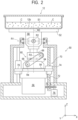
- FIG. 2 is a schematic partial sectional view of the tilting device in the culture apparatus.
- FIG. 3 is a schematic partial sectional view of a part of the tilting device as viewed from a different direction.
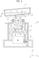
- FIG. 4 is a schematic partial sectional view of the tilting device in a state in which a stage is tilted.
- the tilting device 50 includes a stage 52 on which the culture vessel 12 is to be placed, and a rotary actuator 56 including a rotary table 54 which rotates about a rotation center axis R0 extending in the vertical direction (Z axis direction).
- the stage 52 and the rotary actuator 56 are drivingly coupled to each other via a rocking head 58 and a tilting mechanism 60.
- the rocking head 58 is provided in the tilting device 50 so as to support the stage 52 and to be rockable about a rocking axis R1 extending in the horizontal direction (X axis direction) and a rocking axis R2 extending in the horizontal direction (Y axis direction) and being orthogonal to the rocking axis R1. Further, the rocking head 58 includes, in a lower portion thereof, a coupling shaft 62 to be drivingly coupled to the rotary actuator 56 via the tilting mechanism 60. When the stage 52 takes a horizontal posture, the coupling shaft 62 of the rocking head 58 extends in the vertical direction (Z axis direction).
- the tilting mechanism 60 is a link mechanism for tilting the stage 52 via the rocking head 58, that is, tilting the culture vessel 12 on the stage 52 with respect to the horizontal direction.
- the tilting mechanism 60 includes a base portion 64, a rocking head coupling portion 66 coupled to the rocking head 58, and link arms 68 for coupling the base portion 64 and the rocking head coupling portion 66 to each other.
- the base portion 64 of the tilting mechanism 60 is mounted to the rotary table 54 of the rotary actuator 56.
- the base portion 64 rotates together with the rotary table 54 about the rotation center axis R0.
- the rocking head coupling portion 66 of the tilting mechanism 60 is inserted over the coupling shaft 62 of the rocking head 58 so as to be slidable through intermediation of, for example, a bearing or the like.
- the link arms 68 of the tilting mechanism 60 are configured to couple the base portion 64 and the rocking head coupling portion 66 to each other.
- each of the link arms 68 includes one end turnably fixed to the rocking head coupling portion 66, and another end turnably fixed to the base portion 64.
- a turning axis R3 at the one end of each of the link arms 68 and a rotation axis R4 at the another end thereof each extend in the horizontal direction, and are parallel to each other.
- the rotary actuator 56 having the base portion 64 of the tilting mechanism 60 mounted thereon is raised and lowered in the vertical direction (Z axis direction) by a ball screw mechanism 70.
- the ball screw mechanism 70 includes a screw shaft 72 extending in the vertical direction (Z axis direction), a nut 74 engaged with the screw shaft 72, and a motor 76 for rotating the screw shaft 72.
- the nut 74 is mounted to a raising/lowering bracket 78.
- the rotary actuator 56 is mounted to this raising/lowering bracket 78.
- the rotary actuator 56 When the motor 76 of the ball screw mechanism 70 is driven, the rotary actuator 56 is raised and lowered together with the raising/lowering bracket 78 via the screw shaft 72 and the nut 74.
- the stage 52 is tilted via the tilting mechanism 60.
- the base portion 64 of the tilting mechanism 60 mounted to the rotary actuator 56 is raised so that the link arms 68 push the rocking head coupling portion 66.
- the rocking head 58 rotates together with the rocking head coupling portion 66 about at least one of the rocking axis R1 or the rocking axis R2 (rocking axis R2 in FIG. 5 ).
- the stage 52 is tilted, and the culture vessel 12 on this stage 52 is also tilted.
- the culture vessel 12 is tilted with respect to the horizontal direction.
- the tilting mechanism 60 rotates about the rotation center axis R0 so that a tilt direction of the stage 52 in top view (as viewed in Z axis direction), that is, a tilt direction TD of the culture vessel 12 changes.
- the culture solution S1 in the culture vessel 12 is agitated and the cells C in the culture solution S1 are cultured.
- the expansion culture can be executed through use of only one culture vessel 12. Specifically, when agitating conditions (tilt angle ⁇ of the stage 52, and rotation angle range and rotation speed of the rotary actuator 56) are changed depending on a liquid amount of the culture solution S1 in the culture vessel 12, culture solutions S1 in a small amount to a large amount can be agitated with agitating conditions suitable for cell growth.
- agitating conditions tilt angle ⁇ of the stage 52, and rotation angle range and rotation speed of the rotary actuator 56
- the configuration of the culture apparatus 10 has been described so far. Now, an operation of the culture apparatus 10, in particular, replacement of the culture solution S1 in the culture vessel 12 is described.
- FIG. 5 is a block diagram for illustrating a control system of the culture apparatus, which is associated with the replacement of the culture solution in the culture vessel.
- the culture apparatus 10 includes a controller 80 and a weight sensor 82.
- the controller 80 controls the plurality of pumps 22, 24, and 26, the plurality of on-off valves 28, 30, 32, 34, and 36, and the tilting device 50 (the rotary actuator 56 and the motor 76).
- the controller 80 includes, for example, a processor such as a CPU or an MPU, a storage device such as a memory, and a circuit.
- the storage device stores a program that causes the processor to execute various operations.
- the circuit electrically connects the processor and devices external to the controller 80, such as the plurality of pumps 22 to 26, the plurality of on-off valves 28 to 36, and the tilting device 50, to each other.
- the controller 80 controls the plurality of pumps 22, 24, and 26, the plurality of on-off valves 28, 30, 32, 34, and 36, and the tilting device 50 based on, for example, a cell culture schedule that has been created by a user and stored in the storage device to thereby execute the culture of the cells C.
- the cell culture schedule includes a replacement timing for the culture solution S1 in the culture vessel 12.
- the controller 80 executes the replacement of the culture solution S1 in the culture vessel 12 during the culture of the cells C in accordance with the cell culture schedule.
- the weight sensor 82 is a sensor configured to measure weight of the culture vessel 12. A role of the weight sensor 82 is described later.
- the controller 80 starts executing the following control.
- the replacement of the culture solution S1 is performed by collecting almost all the culture solution S1 stored in the culture vessel 12 into the liquid waste collection vessel 18 and then supplying the fresh culture solution S1 stored in the culture solution supply vessel 14 into the culture vessel 12.
- FIG. 6A to FIG. 10A are top views of the culture vessel during the replacement of the culture solution. Further, FIG. 6B to FIG. 10B are sectional views of the culture vessel during the replacement of the culture solution. FIG. 6B to FIG. 10B are sectional views taken along the tilt direction TD of the culture vessel 12 and the vertical direction (Z axis direction).
- the controller 80 starts controlling the motor 76 for the tilting device 50 to tilt the culture vessel 12 by a predetermined angle ⁇ with respect to the horizontal direction so that the culture solution S1 has the largest liquid depth at a position far from a suction range SR for the suction port 40a of the suction nozzle 40.
- the cell vessel 12 is tilted as described above so as to cause the cells C1 floating in the culture solution S1 to be precipitated in a corner portion defined by the side wall portion 12a and the bottom surface 12b of the culture vessel 12, which is at the position far from the suction range SR for the suction port 40a of the suction nozzle 40.
- the predetermined angle ⁇ is determined by elapsed time from start of the culture, that is, the number of cells in the culture vessel 12. Further, a speed at which the culture vessel 12 is tilted by the predetermined angle ⁇ with respect to the horizontal direction is set so as not to apply stress to the cells. For example, the culture vessel 12 is only required to be tilted at a speed that does not cause a liquid surface of the culture solution S1 to be ruffled so that stress applied to the cells is reduced. Further, an ability of the weight sensor 82 to detect waves on the liquid surface of the culture solution S1 may also be used.
- the speed at which the culture vessel 12 is tilted is only required to be decreased so as to reduce stress on the cells. Further, the speed at which the culture vessel 12 is tilted may be set so that a Reynolds number becomes equal to or smaller than a predetermined value, for example, 2,300 or smaller.
- the suction range SR is a range in which the culture solution S1 can be sucked through the suction nozzle 40 and is determined depending on a size of the suction port 40a of the suction nozzle 40 and power of the pump 22.
- the tilting device 50 tilts the culture vessel 12 in the tilt direction TD so that the culture solution S1 has the largest liquid depth at the position far from the suction range SR for the suction port 40a of the suction nozzle 40.
- the cells C are precipitated in the vicinity of the supply nozzle 42 that is opposed to the suction nozzle 40 located at the maximum distance therefrom.
- suction of the culture solution S1 stored in the culture vessel 12 through the suction nozzle 40 is started.
- the controller 80 brings the on-off valve 30 into a closed state while bringing the on-off valve 28 into an open state and actuates the pump 22.
- the culture solution S1 in the culture vessel 12 is moved into the liquid waste collection vessel 18.
- the culture solution S1 around the cells C in a precipitated state is away from the suction port 40a of the suction nozzle 40, and thus does not substantially flow.
- stress is not substantially applied from the culture solution S1 on the cells C.
- the tilting device 50 changes the tilt direction TD of the culture vessel 12 as the culture solution S1 stored in the culture vessel 12 is being decreased due to the suction through the suction nozzle 40. More specifically, the tilting device 50 changes the tilt direction TD of the culture vessel 12 so that the suction port 40a remains positioned below the liquid level FL of the culture solution S1 that continuously falls due to the suction through the suction nozzle 40.
- the weight sensor 82 measures weight of the culture vessel 12.
- Weight of the culture solution S1 can be obtained by subtracting the weight of the culture vessel 12 from the result of measurement performed by the weight sensor 82.
- An accommodation amount of the culture solution S1 in the culture vessel 12 can be obtained from the calculated weight.
- a height position of the liquid level FL of the culture solution S1 in the culture vessel 12 can be obtained from the accommodation amount of the culture solution S1, an internal shape of the culture vessel 12, and the tilt angle ⁇ of the culture vessel 12.
- the tilt direction TD of the culture vessel 12 which is required to position the suction port 40a of the suction nozzle 40 below the liquid level FL, can be obtained.
- the controller 80 controls the tilting device 50 (the rotary actuator 56 thereof) based on the result of measurement performed by the weight sensor 82.
- the tilting device 50 changes the tilt direction TD of the culture vessel 12 so that the suction port 40a remains positioned below the liquid level FL of the culture solution S1 that continuously falls due to the suction through the suction nozzle 40.
- the tilt direction TD of the culture vessel 12 is changed so that the cells C precipitated at the position at which the culture solution S1 has the largest liquid depth are moved closer to the suction nozzle 40.
- the controller 80 After the collection of the culture solution S1 that has been stored in the culture vessel 12 into the liquid waste collection vessel 18 is completed, the controller 80 starts supply of the culture solution S1 stored in the culture solution supply vessel 14 into the culture vessel 12. First, the controller 80 brings the on-off valve 28 into a closed state and stops the pump 22. Subsequently, the controller 80 brings the on-off valve 32 into an open state and actuates the pump 24. Thus, the culture solution S1 stored in the culture solution supply vessel 14 is supplied into the culture vessel 12 via the supply nozzle 42.
- the tilting device 50 tilts the culture vessel 12 so that the culture solution has the largest liquid depth at the position far from the supply port 42a of the supply nozzle 42.
- the cells C are precipitated at the position.
- the tilting device 50 tilts the culture vessel 12 in the tilt direction TD so that the cells C are precipitated at the position "farthest" away from the supply port 42a of the supply nozzle 42.
- the cells C are precipitated in the vicinity of the suction nozzle 40 that is opposed to the supply nozzle 42 located at the maximum distance therefrom.
- the suction nozzle 40 and the supply nozzle 42 are arranged at the maximum distance from each other inside the culture vessel 12 so as to be opposed to each other.
- the culture solution S1 flowing out from the supply port 42a of the supply nozzle 42 flows on the bottom surface 12a of the culture vessel 12 to reach the precipitated cells C. Then, ultimately, the cells C are immersed in the culture solution S1 supplied from the supply nozzle 42. It is preferred that a supply speed at which the culture solution S1 is supplied from the supply port 42a of the supply nozzle 42 into the culture vessel 12 be such that the cells C are allowed to be maintained in a precipitated state in the culture solution S1. With this setting of the speed, stress applied to the cells C can be reduced.
- the controller 80 closes the on-off valve 32 and stops the pump 24. Thus, the replacement of the culture solution S1 in the culture vessel 12 is completed. Then, the controller 80 controls the tilting device 50 to restart the agitation of the culture solution S1 in the culture vessel 12.
- the replacement of the culture solution S1 in the culture vessel 12 can also be performed by another method. More specifically, the culture solution S1 is supplied into the culture vessel 12 through the supply nozzle 42 while the culture solution S1 in the culture vessel 12 is being sucked through the suction nozzle 40. In this manner, the replacement of the culture solution S1 in the culture vessel 12 can be performed in a short period of time.
- the tilting device 50 tilts the culture vessel 12 so that a position inside the culture vessel 12, which is at an equal distance from the suction nozzle 40 and from the supply nozzle 42, is a position at which the culture solution has the largest liquid depth and the cells C are precipitated at the position.
- the suction of the culture solution S1 stored in the culture vessel 12 through the suction nozzle 40 and the supply of the culture solution S1 into the culture vessel 12 through the supply nozzle 42 can be simultaneously performed while stress on the cells C is reduced.
- the tilting device 50 tilts the culture vessel 12 so that the position inside the culture vessel 12, which is at the largest distance from each of the suction nozzle 40 and the supply nozzle 42, is a position at which the culture solution has the largest liquid depth.
- the cells C are precipitated at the position.
- the culture solution S1 in the culture vessel 12 can be clarified while stress on the cells C is reduced.
- the amount (supply amount) of the liquid containing the culture solution S1, which has been filtered through the hollow fiber membrane filter 20, to be returned to the culture vessel 12 may be adjusted based on the result of measurement performed by the weight sensor 82. More specifically, the supply amount of the liquid containing the culture solution S1, which has been filtered through the filter 20, into the culture vessel 12 may be adjusted so that a time rate of change of the measurement value obtained by the weight sensor 82 falls within a predetermined range, that is, the amount of the culture solution S1 stored in the culture vessel 12 does not rapidly change. In this manner, a large change in culture environment can be suppressed, and thus stress on the cells C can be reduced.
- the wash solution S2 in the wash solution supply vessel 16 is supplied into the culture vessel 12 via the supply nozzle 42.
- the culture solution S1 in the culture vessel 12 is replaced by the wash solution S2.
- the tilting device 50 tilts the culture vessel so that the culture solution has the largest liquid depth at a position far from the supply port 42a of the supply nozzle 42, and the cells C are precipitated at the position.
- the culture apparatus 10 also has a function to suck an adequate amount of the culture solution S1 from the culture vessel 12 through the suction nozzle 40 after supplying the culture solution S1 into the culture vessel 12 through the supply nozzle 42. With this function, the cells C can be brought into contact with the fresh culture solution S1 while the amount of the old culture solution S1 in the culture vessel 12 is being reduced without a large reduction in the amount of the culture solution S1 with which the cells C in the culture vessel 12 are in contact.
- the culture apparatus 10 also has a function to increase, decrease, or keep constant the amount of the culture solution S1 in the culture vessel 12 while diluting the old culture solution S1 with the fresh culture solution S1 through the adjustment of the supply amount of the culture solution S1 into the culture vessel 12 and the suction amount of the culture solution S1 sucked from the culture vessel 12.
- control of the amount of the culture solution S 1 and the dilution thereof in accordance with a state of the cells C in the culture vessel 12 can be achieved.
- culture medium replacement which is performed also in this embodiment, dilution at a super high rate is performed as in an operation of sucking liquid separated from the cells through centrifugal separation and seeding the cells in a fresh culture liquid.
- the centrifugal separation cannot be performed in the culture medium replacement for the culture solution in the vessel.
- a precipitation property of the cells is used for the culture medium replacement.
- the dilution at a low rate is less efficient than the centrifugal separation.
- the above-mentioned culture medium replacement operation is effective in the culture medium replacement for a large amount of cells to be cultured with single-use vessels.
- the suction amount of the culture solution can be set based on a liquid amount calculated from the result of measurement performed by the weight sensor and a specific gravity of the liquid.
- suction of an appropriate amount of the old culture solution and supply of an appropriate amount of the fresh culture solution for culture medium replacement can be performed.
- one suction nozzle 40 and one supply nozzle 42 are provided in the culture vessel 12.
- the suction nozzle and the supply nozzle according to the embodiment of the present disclosure are not limited to those described above.
- FIG. 11 is a schematic view for illustrating a configuration of a culture apparatus according to another embodiment of the present disclosure.
- a plurality of suction nozzles 140A to 140C and a plurality of supply nozzles 142A to 142C are provided in a culture vessel 12.
- the plurality of suction nozzles 140A to 140C are connected to a pump 22.
- On-off valves 144A to 144C are arranged between the plurality of suction nozzles 140A to 140C and the pump 22, respectively. Further, distances from suction ports 140a of the plurality of suction nozzles 140A to 140C to a bottom surface 12a of the culture vessel 12 are different from each other.
- the plurality of supply nozzles 142A to 142C are connected to a pump 24.
- On-off valves 146A to 146C are arranged between the plurality of supply nozzles 142A to 142C and the pump 24, respectively. Further, distances from supply ports 142a of the plurality of supply nozzles 142A to 142C to the bottom surface 12a of the culture vessel 12 are different from each other.
- the plurality of suction nozzles 140A to 140C and the plurality of supply nozzles 142A to 142C described above allow replacement of a culture solution S1 in the culture vessel 12 by various methods. For example, while the culture solution S1 is being sucked through any of the suction nozzles, each with the suction port 140a positioned below a liquid level FL of the culture solution S1, the culture solution S1 can be supplied into the culture vessel 12 through any of the supply nozzles, each with the supply port 142a exposed from the culture solution S1. Specifically, an optimal replacement method for the culture solution S1 in accordance with the kind of cells C can be put into practice.
- the tilting device 50 can tilt the culture vessel 12 in a plurality of different directions in top view by using the rotary actuator 56 and the motor 76 as drive sources and adopting the link mechanism.
- the tilting device according to the embodiments of the present disclosure is not limited to that described above.
- the tilting device of the culture apparatus according to the embodiments of the present disclosure may have any structure as long as the tilting device can tilt the culture vessel in a plurality of different directions in top view.
- the liquid amount of the culture solution S1 in the culture vessel 12 is obtained based on the result of measurement performed by the weight sensor 82.
- a way of obtaining the liquid amount according to the embodiments of the present disclosure is not limited to that described above.
- the liquid amount of the culture solution S1 in the culture vessel 12 can be obtained from a cumulative supply amount of the culture solution supplied through the supply nozzle and a cumulative collection amount of the culture solution collected through the suction nozzle.
- Each of the cumulative supply amount and the cumulative collection amount can be calculated from drive time of each of the pumps and a feed amount per unit time from each of the pumps.
- the culture apparatus includes, in a broad sense, the culture vessel configured to accommodate the culture solution for culturing the cells, the tilting device configured to enable tilting of the culture vessel in the plurality of different directions in top view, and the suction nozzle having the suction port through which the culture solution in the culture vessel is sucked, the suction port being arranged inside the culture vessel.
- the tilting device tilts the culture vessel so that the culture liquid has the largest liquid depth at the position far from the suction range for the suction port of the suction nozzle.
- the culture apparatus includes, in a broad sense, the culture vessel configured to accommodate the culture solution for culturing the cells, the tilting device configured to enable tilting of the culture vessel in the plurality of different directions in top view, and the supply nozzle having the supply port through which the culture solution is supplied into the culture vessel, the supply port being arranged inside the culture vessel.
- the tilting device tilts the culture vessel so that the culture liquid has the largest liquid depth at the position far from the supply port of the supply nozzle.
- the present disclosure is applicable to cell culture for culturing cells while a culture solution is agitated.
Landscapes
- Wood Science & Technology (AREA)
- Life Sciences & Earth Sciences (AREA)
- Engineering & Computer Science (AREA)
- Bioinformatics & Cheminformatics (AREA)
- Health & Medical Sciences (AREA)
- Organic Chemistry (AREA)
- Chemical & Material Sciences (AREA)
- Zoology (AREA)
- Biomedical Technology (AREA)
- Sustainable Development (AREA)
- Microbiology (AREA)
- Biochemistry (AREA)
- General Engineering & Computer Science (AREA)
- General Health & Medical Sciences (AREA)
- Genetics & Genomics (AREA)
- Biotechnology (AREA)
- Apparatus Associated With Microorganisms And Enzymes (AREA)
Applications Claiming Priority (2)
| Application Number | Priority Date | Filing Date | Title |
|---|---|---|---|
| JP2022072630A JP2023161962A (ja) | 2022-04-26 | 2022-04-26 | 培養装置 |
| PCT/JP2023/004814 WO2023210107A1 (ja) | 2022-04-26 | 2023-02-13 | 培養装置 |
Publications (2)
| Publication Number | Publication Date |
|---|---|
| EP4502131A1 true EP4502131A1 (de) | 2025-02-05 |
| EP4502131A4 EP4502131A4 (de) | 2026-04-01 |
Family
ID=88518540
Family Applications (1)
| Application Number | Title | Priority Date | Filing Date |
|---|---|---|---|
| EP23795855.8A Pending EP4502131A4 (de) | 2022-04-26 | 2023-02-13 | Kulturvorrichtung |
Country Status (4)
| Country | Link |
|---|---|
| US (1) | US20250066705A1 (de) |
| EP (1) | EP4502131A4 (de) |
| JP (1) | JP2023161962A (de) |
| WO (1) | WO2023210107A1 (de) |
Family Cites Families (9)
| Publication number | Priority date | Publication date | Assignee | Title |
|---|---|---|---|---|
| JPH037575A (ja) * | 1989-03-30 | 1991-01-14 | Shimadzu Corp | 細胞培養装置 |
| KR100575461B1 (ko) * | 2004-07-23 | 2006-05-03 | 삼성정밀화학 주식회사 | 생물 배양 장치 및 방법 |
| JP2010046568A (ja) * | 2008-08-19 | 2010-03-04 | Olympus Corp | 遠心分離装置 |
| US20120100576A1 (en) * | 2009-07-08 | 2012-04-26 | Glycotope Gmbh | Perfusion bioreactor |
| US9550969B2 (en) * | 2011-03-18 | 2017-01-24 | Ge Healthcare Bio-Sciences Ab | Flexible bag for cultivation of cells |
| JP6832586B2 (ja) | 2015-11-06 | 2021-02-24 | 学校法人日本大学 | 培養容器 |
| JP2022123160A (ja) * | 2019-07-04 | 2022-08-24 | 株式会社京都製作所 | 培養装置および培養方法 |
| JP7486160B2 (ja) * | 2020-05-25 | 2024-05-17 | パナソニックIpマネジメント株式会社 | 細胞培養装置および細胞培養方法 |
| WO2022030365A1 (ja) * | 2020-08-04 | 2022-02-10 | 株式会社京都製作所 | 培養装置 |
-
2022
- 2022-04-26 JP JP2022072630A patent/JP2023161962A/ja active Pending
-
2023
- 2023-02-13 WO PCT/JP2023/004814 patent/WO2023210107A1/ja not_active Ceased
- 2023-02-13 EP EP23795855.8A patent/EP4502131A4/de active Pending
-
2024
- 2024-10-18 US US18/919,927 patent/US20250066705A1/en active Pending
Also Published As
| Publication number | Publication date |
|---|---|
| WO2023210107A1 (ja) | 2023-11-02 |
| US20250066705A1 (en) | 2025-02-27 |
| EP4502131A4 (de) | 2026-04-01 |
| JP2023161962A (ja) | 2023-11-08 |
Similar Documents
| Publication | Publication Date | Title |
|---|---|---|
| CN208026491U (zh) | 一种水质监测无人机自动采样装置 | |
| CN109515012A (zh) | 一种高温玻璃数码喷墨打印机 | |
| EP4502131A1 (de) | Kulturvorrichtung | |
| JP2019000043A (ja) | 培養装置および培養方法 | |
| KR102354250B1 (ko) | 관류 배양장치 및 원심분리기 | |
| CN112326393A (zh) | 一种细胞自动制片仪 | |
| CN109513250A (zh) | 过滤系统及用于过滤流体的过滤方法 | |
| JP3387942B2 (ja) | 自動化学分析システム | |
| CN215588854U (zh) | 抛光液输送系统 | |
| CN215910468U (zh) | 智能污水在线检测装置 | |
| JP2000023594A (ja) | 養魚用餌料生物の自動培養・給餌システム | |
| CN209955514U (zh) | 一种油墨粘度控制器 | |
| JP2006075782A (ja) | 曝気槽の泡抑制装置及びそれを備えた生ごみ処理装置 | |
| CN213376193U (zh) | 一种金属清洗剂搅拌设备 | |
| CN114949944A (zh) | 料浆分离系统、料浆分离方法及稠厚器 | |
| CN222099606U (zh) | 一种新型无气水制备装置 | |
| CN113466013B (zh) | 一种用于玻璃蒙砂工艺测试打样装置及方法 | |
| JPH1157945A (ja) | どぶ漬装置 | |
| CN223189188U (zh) | 一种细胞分离用筛选装置 | |
| CN224035394U (zh) | 一种用于检测水质氨氮的分析装置 | |
| CN222956599U (zh) | 一种提纯装置 | |
| CN222820585U (zh) | 一种可液位检测的污泥缓存斗 | |
| CN220801593U (zh) | 一种吸痰器 | |
| CN223819247U (zh) | 一种多级自动清洗装置 | |
| CN224025483U (zh) | 液体供收装置以及匀胶系统 |
Legal Events
| Date | Code | Title | Description |
|---|---|---|---|
| STAA | Information on the status of an ep patent application or granted ep patent |
Free format text: STATUS: THE INTERNATIONAL PUBLICATION HAS BEEN MADE |
|
| PUAI | Public reference made under article 153(3) epc to a published international application that has entered the european phase |
Free format text: ORIGINAL CODE: 0009012 |
|
| STAA | Information on the status of an ep patent application or granted ep patent |
Free format text: STATUS: REQUEST FOR EXAMINATION WAS MADE |
|
| 17P | Request for examination filed |
Effective date: 20241025 |
|
| AK | Designated contracting states |
Kind code of ref document: A1 Designated state(s): AL AT BE BG CH CY CZ DE DK EE ES FI FR GB GR HR HU IE IS IT LI LT LU LV MC ME MK MT NL NO PL PT RO RS SE SI SK SM TR |
|
| DAV | Request for validation of the european patent (deleted) | ||
| DAX | Request for extension of the european patent (deleted) | ||
| A4 | Supplementary search report drawn up and despatched |
Effective date: 20260304 |
|
| RIC1 | Information provided on ipc code assigned before grant |
Ipc: C12M 1/00 20060101AFI20260226BHEP Ipc: C12M 1/02 20060101ALI20260226BHEP Ipc: C12M 3/06 20060101ALI20260226BHEP |