EP4502189A1 - Kornorientierte magnetische stahlplatte und herstellungsverfahren dafür - Google Patents
Kornorientierte magnetische stahlplatte und herstellungsverfahren dafür Download PDFInfo
- Publication number
- EP4502189A1 EP4502189A1 EP23780341.6A EP23780341A EP4502189A1 EP 4502189 A1 EP4502189 A1 EP 4502189A1 EP 23780341 A EP23780341 A EP 23780341A EP 4502189 A1 EP4502189 A1 EP 4502189A1
- Authority
- EP
- European Patent Office
- Prior art keywords
- magnetic domain
- groove
- grain
- region
- steel sheet
- Prior art date
- Legal status (The legal status is an assumption and is not a legal conclusion. Google has not performed a legal analysis and makes no representation as to the accuracy of the status listed.)
- Pending
Links
Images




Classifications
-
- H—ELECTRICITY
- H01—ELECTRIC ELEMENTS
- H01F—MAGNETS; INDUCTANCES; TRANSFORMERS; SELECTION OF MATERIALS FOR THEIR MAGNETIC PROPERTIES
- H01F1/00—Magnets or magnetic bodies characterised by the magnetic materials therefor; Selection of materials for their magnetic properties
- H01F1/01—Magnets or magnetic bodies characterised by the magnetic materials therefor; Selection of materials for their magnetic properties of inorganic materials
- H01F1/03—Magnets or magnetic bodies characterised by the magnetic materials therefor; Selection of materials for their magnetic properties of inorganic materials characterised by their coercivity
- H01F1/12—Magnets or magnetic bodies characterised by the magnetic materials therefor; Selection of materials for their magnetic properties of inorganic materials characterised by their coercivity of soft-magnetic materials
- H01F1/14—Magnets or magnetic bodies characterised by the magnetic materials therefor; Selection of materials for their magnetic properties of inorganic materials characterised by their coercivity of soft-magnetic materials metals or alloys
-
- C—CHEMISTRY; METALLURGY
- C21—METALLURGY OF IRON
- C21D—MODIFYING THE PHYSICAL STRUCTURE OF FERROUS METALS; GENERAL DEVICES FOR HEAT TREATMENT OF FERROUS OR NON-FERROUS METALS OR ALLOYS; MAKING METAL MALLEABLE, e.g. BY DECARBURISATION OR TEMPERING
- C21D8/00—Modifying the physical properties of ferrous metals or ferrous alloys by deformation combined with, or followed by, heat treatment
- C21D8/12—Modifying the physical properties of ferrous metals or ferrous alloys by deformation combined with, or followed by, heat treatment during manufacturing of articles with special electromagnetic properties
- C21D8/1294—Modifying the physical properties of ferrous metals or ferrous alloys by deformation combined with, or followed by, heat treatment during manufacturing of articles with special electromagnetic properties involving a localised treatment
-
- H—ELECTRICITY
- H01—ELECTRIC ELEMENTS
- H01F—MAGNETS; INDUCTANCES; TRANSFORMERS; SELECTION OF MATERIALS FOR THEIR MAGNETIC PROPERTIES
- H01F1/00—Magnets or magnetic bodies characterised by the magnetic materials therefor; Selection of materials for their magnetic properties
- H01F1/01—Magnets or magnetic bodies characterised by the magnetic materials therefor; Selection of materials for their magnetic properties of inorganic materials
- H01F1/03—Magnets or magnetic bodies characterised by the magnetic materials therefor; Selection of materials for their magnetic properties of inorganic materials characterised by their coercivity
- H01F1/12—Magnets or magnetic bodies characterised by the magnetic materials therefor; Selection of materials for their magnetic properties of inorganic materials characterised by their coercivity of soft-magnetic materials
- H01F1/14—Magnets or magnetic bodies characterised by the magnetic materials therefor; Selection of materials for their magnetic properties of inorganic materials characterised by their coercivity of soft-magnetic materials metals or alloys
- H01F1/147—Alloys characterised by their composition
- H01F1/14766—Fe-Si based alloys
- H01F1/14791—Fe-Si-Al based alloys, e.g. Sendust
-
- C—CHEMISTRY; METALLURGY
- C21—METALLURGY OF IRON
- C21D—MODIFYING THE PHYSICAL STRUCTURE OF FERROUS METALS; GENERAL DEVICES FOR HEAT TREATMENT OF FERROUS OR NON-FERROUS METALS OR ALLOYS; MAKING METAL MALLEABLE, e.g. BY DECARBURISATION OR TEMPERING
- C21D8/00—Modifying the physical properties of ferrous metals or ferrous alloys by deformation combined with, or followed by, heat treatment
- C21D8/12—Modifying the physical properties of ferrous metals or ferrous alloys by deformation combined with, or followed by, heat treatment during manufacturing of articles with special electromagnetic properties
- C21D8/1277—Modifying the physical properties of ferrous metals or ferrous alloys by deformation combined with, or followed by, heat treatment during manufacturing of articles with special electromagnetic properties involving a particular surface treatment
-
- C—CHEMISTRY; METALLURGY
- C21—METALLURGY OF IRON
- C21D—MODIFYING THE PHYSICAL STRUCTURE OF FERROUS METALS; GENERAL DEVICES FOR HEAT TREATMENT OF FERROUS OR NON-FERROUS METALS OR ALLOYS; MAKING METAL MALLEABLE, e.g. BY DECARBURISATION OR TEMPERING
- C21D9/00—Heat treatment, e.g. annealing, hardening, quenching or tempering, adapted for particular articles; Furnaces therefor
- C21D9/46—Heat treatment, e.g. annealing, hardening, quenching or tempering, adapted for particular articles; Furnaces therefor for sheet metals
-
- C—CHEMISTRY; METALLURGY
- C22—METALLURGY; FERROUS OR NON-FERROUS ALLOYS; TREATMENT OF ALLOYS OR NON-FERROUS METALS
- C22C—ALLOYS
- C22C38/00—Ferrous alloys, e.g. steel alloys
- C22C38/02—Ferrous alloys, e.g. steel alloys containing silicon
-
- H—ELECTRICITY
- H01—ELECTRIC ELEMENTS
- H01F—MAGNETS; INDUCTANCES; TRANSFORMERS; SELECTION OF MATERIALS FOR THEIR MAGNETIC PROPERTIES
- H01F1/00—Magnets or magnetic bodies characterised by the magnetic materials therefor; Selection of materials for their magnetic properties
- H01F1/01—Magnets or magnetic bodies characterised by the magnetic materials therefor; Selection of materials for their magnetic properties of inorganic materials
- H01F1/03—Magnets or magnetic bodies characterised by the magnetic materials therefor; Selection of materials for their magnetic properties of inorganic materials characterised by their coercivity
- H01F1/12—Magnets or magnetic bodies characterised by the magnetic materials therefor; Selection of materials for their magnetic properties of inorganic materials characterised by their coercivity of soft-magnetic materials
- H01F1/14—Magnets or magnetic bodies characterised by the magnetic materials therefor; Selection of materials for their magnetic properties of inorganic materials characterised by their coercivity of soft-magnetic materials metals or alloys
- H01F1/16—Magnets or magnetic bodies characterised by the magnetic materials therefor; Selection of materials for their magnetic properties of inorganic materials characterised by their coercivity of soft-magnetic materials metals or alloys in the form of sheets
-
- C—CHEMISTRY; METALLURGY
- C21—METALLURGY OF IRON
- C21D—MODIFYING THE PHYSICAL STRUCTURE OF FERROUS METALS; GENERAL DEVICES FOR HEAT TREATMENT OF FERROUS OR NON-FERROUS METALS OR ALLOYS; MAKING METAL MALLEABLE, e.g. BY DECARBURISATION OR TEMPERING
- C21D2201/00—Treatment for obtaining particular effects
- C21D2201/05—Grain orientation
-
- H—ELECTRICITY
- H01—ELECTRIC ELEMENTS
- H01F—MAGNETS; INDUCTANCES; TRANSFORMERS; SELECTION OF MATERIALS FOR THEIR MAGNETIC PROPERTIES
- H01F41/00—Apparatus or processes specially adapted for manufacturing or assembling magnets, inductances or transformers; Apparatus or processes specially adapted for manufacturing materials characterised by their magnetic properties
- H01F41/02—Apparatus or processes specially adapted for manufacturing or assembling magnets, inductances or transformers; Apparatus or processes specially adapted for manufacturing materials characterised by their magnetic properties for manufacturing cores, coils, or magnets
- H01F41/0206—Manufacturing of magnetic cores by mechanical means
- H01F41/0233—Manufacturing of magnetic circuits made from sheets
Definitions
- the present disclosure relates to a grain-oriented electrical steel sheet and a manufacturing method therefore.
- a grain-oriented electrical steel sheet is a steel sheet containing 7% by mass or less of Si and having a secondary recrystallization texture in which secondary recrystallized grains are accumulated in the ⁇ 110 ⁇ 001> orientation (Goss orientation).
- the grain-oriented electrical steel sheet is mainly used as a core of an electric power transformer, and there is an increasing need for reduction of noise in addition to reduction of energy loss (iron loss).
- Patent Documents 1 to 9 discloses a magnetic domain refinement treatment method capable of reducing iron loss without increasing noise. The present inventors considered that it is effective to perform the magnetic domain refinement treatment only on a specific point since the magnetic domain width and the ⁇ angle are not uniform in the grain-oriented electrical steel sheet before the magnetic domain refinement treatment. However, such a magnetic domain refinement treatment method is not disclosed in any patent document.
- An object of the present disclosure is to provide a grain-oriented electrical steel sheet capable of achieving both iron loss reduction and noise reduction, and a manufacturing method therefore.
- the grain-oriented electrical steel sheet according to the embodiment of the present invention it is possible to achieve both iron loss reduction and noise reduction.
- FIG. 1A illustrates a spatial distribution of a width of a 180° magnetic domain of a grain-oriented electrical steel sheet (Hereinafter, it is simply referred to as a "magnetic domain width”.) before a magnetic domain refinement treatment.
- FIG. 1B illustrates the spatial distribution of the magnetic domain width after the magnetic domain refinement treatment is performed on the surface of the grain-oriented electrical steel sheet in FIG. 1A .
- the magnetic domain refinement treatment here is performed by forming a groove along a magnetic domain control treatment line which forms an angle of 0° to 45° with respect to the rolling direction (RD).
- the "180° magnetic domain” refers to a magnetic domain in which the magnetization direction is the ⁇ 100> orientation of the crystal and which is sandwiched between two 180° magnetic walls substantially parallel to the rolling direction.
- the "width” of the 180° magnetic domain refers to a distance between adjacent magnetic walls (magnetic wall interval).
- the spatial distribution of the magnetic domain width shown in FIGS. 1A and 1B is derived from the magnetic domain image of the grain-oriented electrical steel sheet using a two-dimensional Fourier transform described later.
- FIG. 1C illustrates regions where the magnetic domain width is refined by 50 ⁇ m or more before and after the magnetic domain refinement shown in FIGS. 1A and 1B , and visualizes a value of an original magnetic domain width at which refinement occurs.
- the region where the effect of the magnetic domain refinement was 50 ⁇ m or more is a region where the original magnetic domain width is wide, and in particular, the effect of the magnetic domain refinement remarkably appears in a region where the original magnetic domain width is about 500 ⁇ m or more. That is, the effect of magnetic domain refinement varies depending on the original magnetic domain width.
- FIG. 2A shows a relationship between the magnetic domain width before groove formation and the magnetic domain width after groove formation at the same position.
- the depth of the groove is 20 ⁇ m
- the width of the groove is 100 ⁇ m
- the pitch between the grooves is 4mm.
- FIG. 9 illustrates the orthogonal-to-rolling direction (TD) is a direction perpendicular to the rolling direction (RD) and parallel to the sheet surface of the grain-oriented electrical steel sheet.
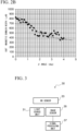
- FIG. 2B illustrates the relationship between the ⁇ angle of the grain-oriented electrical steel sheet and the 180° magnetic domain width before laser irradiation. As can be seen from FIG. 2B , since the region having the ⁇ angle of 2° or less has a wide original magnetic domain width (about 500 ⁇ m or more), it is effective to preferentially perform the magnetic domain refinement treatment on the region having the ⁇ angle of 2° or less, more preferably on the region having the ⁇ angle of 1° or less.
- magnetic domain control is performed so as to preferentially form a groove having a predetermined depth and a predetermined width in a region where the ⁇ angle is 1° or less.
- FIG. 3 illustrates the hardware constitution of the image acquisition device 30 that acquires a magnetic domain image of a grain-oriented electrical steel sheet.
- the image acquisition device 30 includes a light source unit 31, a magneto-optical (MO) sensor 33, an image sensor 35, and a signal processing unit 37.
- MO magneto-optical
- the light source unit 31 includes a light source including a light emitting diode (LED), and irradiates the MO sensor 33 with light having a uniform polarization plane.
- LED light emitting diode
- the MO sensor 33 is a device that measures a structure of a magnetic body, and has an observed section on which a magnetic sample to be measured is placed.
- the light emitted from the light source unit 31 passes through the inside of the MO sensor 33 and is reflected by the reflection layer, and the reflected light passes through the inside of the MO sensor 33 again and is output to the outside of the MO sensor 33.
- a leakage magnetic field corresponding to the direction of spontaneous magnetization of the grain-oriented electrical steel sheet is generated inside the MO sensor 33, and the polarization plane of the reflected light is rotated by the leakage magnetic field.
- the image sensor 35 is a Complementary Metal-Oxide-Semiconductor (CMOS) image sensor, forms an image of reflected light from the MO sensor 33 on a light receiving surface, performs photoelectric conversion, and an analog signal after photoelectric conversion is output to the signal processing unit 37.
- CMOS Complementary Metal-Oxide-Semiconductor
- the spatial distribution of the leakage magnetic field can be obtained by detecting the reflected light in which the polarization plane is rotated by the image sensor 35, and the magnetic domain structure of the grain-oriented electrical steel sheet becomes clear.
- the signal processing unit 37 includes an amplifier, an AD converter, a Digital Signal Processor (DSP), and the like.
- the analog signal output from the image sensor 35 is amplified by an amplifier and converted into a digital signal by an AD converter.
- the DSP performs predetermined digital processing on the digital signal to generate an image signal.
- the image signal generated by the signal processing unit 37 is output to the analysis device 40 (see FIG. 4 ) via a cable or by wireless communication.
- FIG. 4 illustrates a hardware constitution of the analysis device 40 that analyzes the magnetic domain structure of the grain-oriented electrical steel sheet.
- the analysis device 40 is a computer device such as a personal computer (PC), and includes a calculation unit 41, a memory 43, a display unit 45, an input unit 47, and a communication I/F 49.
- PC personal computer
- the calculation unit 41 includes a Central Processing Unit (CPU), analyzes a magnetic domain structure from a magnetic domain image of the grain-oriented electrical steel sheet according to a program stored in the memory 43, and determines a point in which groove is formed. The processing executed by the calculation unit 41 is described in detail later.
- CPU Central Processing Unit
- the memory 43 includes a Read Only Memory (ROM) and a Random Access Memory (RAM).
- the ROM stores programs executed by the CPU of the calculation unit 41 and data required at the time of executing these programs.
- the program and data stored in the ROM are loaded into the RAM and executed.
- the memory 43 may include a magnetic memory such as a hard disk drive (HDD) or an optical memory such as an optical disk.
- the program or data may be stored in a computer-readable recording medium detachable from the analysis device 40.
- the program executed by the calculation unit 41 may be received from the network via the communication I/F 49.
- the display unit 45 includes a display such as a liquid crystal display (LCD), a plasma display, or an organic electroluminescence (EL) display, displays an image on the basis of an image signal output from the image acquisition device 30, and displays an analysis result of the magnetic domain structure by the calculation unit 41.
- a display such as a liquid crystal display (LCD), a plasma display, or an organic electroluminescence (EL) display, displays an image on the basis of an image signal output from the image acquisition device 30, and displays an analysis result of the magnetic domain structure by the calculation unit 41.
- LCD liquid crystal display
- EL organic electroluminescence
- the input unit 47 includes an input device such as a mouse or a keyboard.
- the communication I/F 49 is an interface for transmitting and receiving data to and from an external device via a network such as a Local Area Network (LAN), a Wide Area Network (WAN), or the Internet.
- LAN Local Area Network
- WAN Wide Area Network
- calculation unit 41 instead of general-purpose hardware such as a CPU, dedicated hardware specialized for analyzing a magnetic domain structure, such as an application specific integrated circuit (ASIC) or a Field Programmable Gate Array (FPGA), may be adopted as the calculation unit 41.
- ASIC application specific integrated circuit
- FPGA Field Programmable Gate Array
- FIGS. 3 and 4 illustrate a case where the image acquisition device 30 and the analysis device 40 are separate devices, but a system in which the image acquisition device 30 and the analysis device 40 are integrated may be adopted.
- FIG. 5 illustrates a constitution of the laser irradiation device 500.
- the laser irradiation device 500 includes a polygon mirror 501, a light source device 503, a collimator 505, a condensing lens 507, a motor 509, a sensor 511, a control unit 513, and a sheet passing device 515.
- the sheet passing device 515 passes the grain-oriented electrical steel sheet 50 in the rolling direction (RD).
- the polygon mirror 501 has, for example, a regular polygonal prism shape, and a plurality of plane mirrors is provided on a plurality of side surfaces constituting the regular polygonal prism.
- the laser beam LB enters the plane mirror of the polygon mirror 501 from the light source device 503 via the collimator 505 in one direction (horizontal direction) and is reflected by the plane mirror.
- the polygon mirror 501 is rotatable about the rotation axis O1 by driving from the motor 509.
- the magnetic domain control treatment line 52 forms an angle of 0° to 45° with respect to the orthogonal-to-rolling direction (TD) on the surface of the grain-oriented electrical steel sheet 50, and is a plurality of straight lines aligned in the rolling direction (RD).
- the plurality of magnetic domain control treatment lines 52 extend parallel to each other.
- the plurality of magnetic domain control treatment lines 52 are arranged at equal intervals.
- the interval P between the adjacent magnetic domain control treatment lines 52 represents an interval of groove forming.
- the light source device 503 outputs the laser beam LB by a predetermined irradiation system (for example, a continuous irradiation system or a pulse irradiation system) under the control of the control unit 513.
- a predetermined irradiation system for example, a continuous irradiation system or a pulse irradiation system
- the condensing lens 507 is provided on the optical path of the laser beam LB reflected from the polygon mirror 501, and constitutes a condensing optical system having a predetermined focal length.
- the groove is formed along the magnetic domain control treatment line 52 on the surface of the grain-oriented electrical steel sheet 50.
- the motor 509 is coupled to the polygon mirror 501, and rotationally drives the polygon mirror 501 under the control of the control unit 513.
- the sensor 511 is connected to a drive shaft of the motor 509, detects a rotation angle of the polygon mirror 501 rotated by the motor 509, and outputs a signal indicating the detected rotation angle (Hereinafter, the rotation angle signal is referred to as a rotation angle signal.) to the control unit 513.
- the control unit 513 includes a processor and is connected to the light source device 503, the motor 509, the sensor 511, and the sheet passing device 515.
- the control unit 513 receives an input of a speed signal from the sheet passing device 515, and outputs a signal instructing the motor 509 to rotationally drive the polygon mirror 501.
- control unit 513 controls on and off of the power of the laser beam LB output from the light source device 503 on the basis of a groove formation signal indicating a point in which the groove is formed in the magnetic domain control treatment line 52 and a rotation angle signal output from the sensor 511.
- the groove formation signal is input from the analysis device 40 to the laser irradiation device 500.
- the groove formation signal may be input to the laser irradiation device 500 by an operator.
- the image acquisition device 30 is used to acquire a magnetic domain image of the grain-oriented electrical steel sheet 50 (step S62: image acquisition step).
- the calculation unit 41 of the analysis device 40 derives the spatial distribution of the width (magnetic domain width) of the 180° magnetic domain from the magnetic domain image, and determines the point having the ⁇ angle corresponding to the region where the magnetic domain width is greater than or equal to a predetermined value (for example, about 500 ⁇ m or more), specifically, the point where the ⁇ angle is 1° or less, in the magnetic domain control treatment line 52 of the grain-oriented electrical steel sheet 50, as the point to which the magnetic domain refinement treatment is applied by forming the groove (step S64: determination step).
- a predetermined value for example, about 500 ⁇ m or more
- a point in which groove is formed in the magnetic domain control treatment line 52 is referred to as a "groove formation line”. Details of the processing of the step S64 executed by the calculation unit 41 is described later.
- the point of the groove formation line may be determined by visually observing the magnetic domain image displayed on the display unit 45 by the operator, and a groove formation signal indicating the point of the groove formation line may be input to the laser irradiation device 500.
- the magnetic domain refinement treatment is preferentially performed by forming the groove having a predetermined depth and a predetermined width in the point determined in the step S64 among the magnetic domain control treatment line 52 of the grain-oriented electrical steel sheet 50 (step S66: groove forming step).
- the magnetic domain refinement treatment is performed only on the point determined in the step S64.
- the step S66 may be performed by irradiation with the laser beam LB by the laser irradiation device 500, or other means such as electron beam irradiation, machine processing, and etching may be adopted.
- the calculation unit 41 derives the spatial distribution of the magnetic domain width of the grain-oriented electrical steel sheet 50 using the line segment method or the Fourier transform, and determines a region where the ⁇ angle is 1° or less, which corresponds to a region having the wide magnetic domain width, among the magnetic domain control treatment line 52 of the grain-oriented electrical steel sheet 50 as a point where the groove is preferentially formed.
- evaluation is performed by drawing a line segment perpendicular to the magnetic domain.
- the interval between the line segments is set to 3 lines per 1 cm in a direction parallel to the magnetic domain, and the magnetic domain width is derived from the interval between intersection points of the 180° magnetic wall and the line segment.
- the Fourier transform is particularly effective as a means for analyzing a magnetic domain structure of a magnetic body having a periodic magnetic domain structure such as a grain-oriented electrical steel sheet.
- a method for deriving a spatial distribution of the magnetic domain width of a grain-oriented electrical steel sheet is described using a short-term two-dimensional Fourier transform (Hereinafter, it is referred to as "ST2DFT”.) obtained by expanding a short-term Fourier transform, which is one of signal processing methods that have been used for time-frequency analysis of audio signals for a long time, to a two-dimensional region.
- ST2DFT short-term two-dimensional Fourier transform
- An image (magnetic domain image) represented by an image signal acquired by the image acquisition device 30 is expressed as x (k, l) as a data column of two-dimensional coordinates (k-l coordinates).
- the magnetic domain image to be analyzed is an image binarized by two types of colors such as gray scale, or an image expressed by three or more gradations (multiple gradations).
- the calculation unit 41 executes the following steps (A-1), (A-2), and (A-3).
- a window function Wa (k, l) of a rectangular window in which a range in the k direction is 0 ⁇ k ⁇ N k -1 and a range in the 1 direction is 0 ⁇ 1 ⁇ N l -1 is used (N k and N l are natural numbers).
- the window function Wa (k, l) a Hamming window, a Hanning window, a Blackman window, or the like can be applied.
- N k and N l that define the range of the window function Wa (k, l) are parameters corresponding to the number of pixels in the k direction and the number of pixels in the l direction in the partial region, respectively.
- f k and f l are space frequencies.
- ⁇ k and ⁇ l are the space resolution in the k direction and the space resolution in the l direction in the magnetic domain image, respectively.
- the spatial distribution L (n, m) of the magnetic domain width is derived as in Expression (4) from the resolution of the space frequency defined by Expression (3) and the peak position of the spot of the partial Fourier image.
- L n m 1 ⁇ f k f k max n m 2 + ⁇ f l f l max n m 2
- FIGS. 1A to 1C described above illustrate the analysis result of the magnetic domain width derived by ST2DFT.
- the calculation unit 41 determines, as the groove formation line 90 (solid line in FIG. 9 ) for forming the groove, a point having a ⁇ angle corresponding to a region where the magnetic domain width is a predetermined value or more (for example, about 500 ⁇ m or more), specifically, a point where the ⁇ angle is 1° or less in the magnetic domain control treatment line 52 (broken line in FIG. 9 ) of the grain-oriented electrical steel sheet 50.
- the control unit 513 of the laser irradiation device 500 performs control to turn on the power of the laser beam LB with respect to the groove formation line 90 in the magnetic domain control treatment line 52, and preferably to turn off the power of the laser beam LB with respect to other points. As a result, the groove is formed along the groove formation line 90.
- the groove existence rate which is the rate of a part where a groove having a depth of 5 ⁇ m to 50 ⁇ m and a width of 10 ⁇ m to 300 ⁇ m exists among a total extension of magnetic domain control treatment lines 52 which forms an angle of 0° to 45° with respect to an orthogonal-to-rolling direction (TD) and are arranged in a rolling direction (RD) is 50% or more in a first region which is a region where a ⁇ angle which is a deviation angle of a grain from a Goss orientation around an axis in the orthogonal-to-rolling direction (TD) is 1° or less, and the groove existence rate is less than 50% in a second region where the ⁇ angle is more than 2°.
- the grain-oriented electrical steel sheet 50 has a part where a groove having depth of 5 ⁇ m to 50 ⁇ m and width of 10 ⁇ m to 300 ⁇ m exists.
- the part where a groove having a depth of 5 ⁇ m to 50 ⁇ m and a width of 10 ⁇ m to 300 ⁇ m exists is referred as "groove formation line 90".
- the depth of the groove is 5 ⁇ m to 50 ⁇ m and the width of the groove is 10 ⁇ m to 300 ⁇ m (see patent document 5).
- a groove of which the depth and/or the width are outside the above-described range is not assumed as the groove formation line 90. When the groove existence rate is calculated as described later, the groove of which the depth and/or the width are outside the above-described range is not considered.
- the depth of the groove constituting the groove formation line 90 may be defined as 6 ⁇ m or more, 7 ⁇ m or more, or 10 ⁇ m or more.
- the depth of the groove constituting the groove formation line 90 may be defined as 48 ⁇ m or less, 45 ⁇ m or less, or 40 ⁇ m or less.
- the width of the groove constituting the groove formation line 90 may be defined as 20 ⁇ m or more, 30 ⁇ m or more, or 50 ⁇ m or more.
- the width of the groove constituting the groove formation line 90 may be defined as 280 ⁇ m or less, 250 ⁇ m or less, or 200 ⁇ m or less.
- the depth and the width of the groove may be uniform or may vary within the above-described range in the groove formation line 90.
- the interval P between the adjacent grooves measured along the rolling direction (RD) is preferably 1mm to 20 mm (see patent document 5).
- the interval P between the grooves may be uniform or may vary.
- the interval P between the grooves in only a part of the grain-oriented electrical steel sheet may be 1 mm to 20 mm, or the interval P between the grooves in the entire region of the grain-oriented electrical steel sheet may be 1 mm to 20 mm.
- the average value of the intervals P between the grooves in the grain-oriented electrical steel sheet may be 1 mm to 20 mm.
- the interval P between the adjacent grooves or the average value of the interval P between the grooves may be 2 mm or more, 3 mm or more, or 5 mm or more.
- the interval P between the adjacent grooves or the average value of the interval P between the grooves may be 18 mm or less, 16 mm or less, or 15 mm or less.
- Tension insulating coating may be formed on the surface of the grain-oriented electrical steel sheet.
- the depth of the groove, the width of the groove, and the interval between the grooves along the rolling direction are values of the groove formed in the basis steel sheet.
- the grain-oriented electrical steel sheet has a tension insulating coating
- the depth of the groove, the width of the groove, and the interval between the grooves along the rolling direction are measured after removing the tension insulating coating.
- the groove formation line 90 is disposed on the magnetic domain control treatment line 52.
- the magnetic domain control treatment lines 52 form an angle of 0° to 45° with respect to the orthogonal-to-rolling direction (TD) on the surface of the grain-oriented electrical steel sheet 50, and are arranged along the rolling direction (RD).
- the magnetic domain control treatment lines 52 are preferably arranged in parallel to each other.
- the magnetic domain control treatment line 52 corresponds to the locus of the focal point of the laser beam LB in the manufacture stage of the grain-oriented electrical steel sheet 50.
- the magnetic domain control treatment line 52 does not exist as an entity in the grain-oriented electrical steel sheet 50, but is an imaginary line along the groove formation line 90.
- the magnetic domain control treatment line 52 can be specified by drawing a line along the groove formation line 90.
- the angle formed by the orthogonal-to-rolling direction (TD) and the extending direction of the stress introduction line 90 is the same as the angle formed by the orthogonal-to-rolling direction (TD) and the extending direction of the magnetic domain control treatment line 52 provided with the stress introduction line 90.
- the angle formed by the magnetic domain control treatment line 52 and the orthogonal-to-rolling direction (TD) may be uniform or may vary.
- the angle formed by the magnetic domain control treatment line 52 and the orthogonal-to-rolling direction (TD) may be set to 0° to 45° in only a part of the grain-oriented electrical steel sheet 50, or the angle formed by the magnetic domain control treatment line 52 and the orthogonal-to-rolling direction (TD) may be set to 0° to 45° in all the regions of the grain-oriented electrical steel sheet 50.
- the average value of the angles formed by the magnetic domain control treatment line 52 and the orthogonal-to-rolling direction (TD) in the grain-oriented electrical steel sheet 50 may be set to 0° to 45°.
- the angle formed by the magnetic domain control treatment line 52 and the orthogonal-to-rolling direction (TD) or the average value thereof may be 1° or more, 3° or more, or 5° or more.
- the angle formed by the magnetic domain control treatment line 52 and the orthogonal-to-rolling direction (TD) or the average value thereof may be 40° or less, 35° or less, or 30° or less.
- the groove formation line 90 may exist on the magnetic domain control treatment line 52 in a non-single period. That the groove formation line 90 exists in a non-single period means that the case does not correspond to "the case where there are 10 or more groove formation lines 90 on average per 1 cm, and the standard deviation of the lengths of the non-groove formation lines between the groove formation lines 90 is 20 ⁇ m or less". That is, in the present embodiment, the groove formation line 90 obtained by performing the magnetic domain control by the normal pulse laser on the entire surface of the steel sheet is considered not to "exist in a non-single period". However, a region where the ⁇ angle is 1° or less may be selectively irradiated with a pulse laser.
- the rate of the part (groove formation line 90) where the groove exists in the magnetic domain control treatment line 52 is relatively high, and in the region where the ⁇ angle is large, the rate is relatively low.
- the rate of the groove formation line 90 in the magnetic domain control treatment line 52 is defined as the proportion of the length of the groove formation line 90 to the total extension of the length of the magnetic domain control treatment line 52
- the groove formation line 90 exists at a rate of 50% or more in the first region that is a region where the ⁇ angle is 1° or less
- the groove formation line 90 exists at a rate of less than 50% in the second region where the ⁇ angle is more than 2°.
- the first region may be defined as a region where the ⁇ angle is 1.0° or less, a region where the ⁇ angle is 0.9° or less, or a region where the ⁇ angle is 0.8° or less
- the second region may be defined as a region where the ⁇ angle is more than 2.0°, a region where the ⁇ angle is 2.1° or more, or a region where the ⁇ angle is 2.2° or more.
- the groove existence rate is preferably 20% or more and 80% or less.
- the groove existence rate in each of the first to third regions satisfies the following relationship.
- the third region may be defined as a region where the ⁇ angle is more than 1.0° and 2.0° or less, a region where the ⁇ angle is 1.1° or more and 1.9° or less, or a region where the ⁇ angle is 1.2° or more and 1.8° or less.
- the above-described groove existence rate may be satisfied in a sample having a predetermined size (for example, 100 mm square or more) extracted from any position in the grain-oriented electrical steel sheet 50.
- the magnetic domain refinement treatment is promoted, adverse effects such as an increase in hysteresis loss, deterioration of noise characteristics, and a decrease in magnetic permeability can be minimized, and the effect of magnetic domain refinement can be maximized. This makes it possible to achieve both a reduction in iron loss and a reduction in noise.
- any parameter is performed on a sample of a predetermined size collected from the grain-oriented electrical steel sheet 50.
- a rectangular sample having both sides of 100 mm (or 100 mm or more) in length can be cut out from the grain-oriented electrical steel sheet 50 and subjected to measurement.
- the grain-oriented electrical steel sheet 50 is a coil
- a sample may be collected from an arbitrary point of the coil.
- the grain-oriented electrical steel sheet 50 is a component incorporated in an electrical product such as a transformer or a motor, a sample may be collected from any point of the component.
- the length of one side of the sample may be less than 100 mm.
- the total value of the sample areas is set to 10,000 mm 2 or more. At that time, it is desirable to collect a sample by a method such as wire cutting in order to minimize the influence of mechanical strain or the like on the sample.
- the method for measuring the angle formed by the magnetic domain control treatment line 52 and the orthogonal-to-rolling direction (TD) is as follows.
- the groove formation line 90 included in the sample is specified.
- the position of the groove having the depth of 5 ⁇ m to 50 ⁇ m and the width of 10 ⁇ m to 300 ⁇ m can be specified by measuring the surface of the sample with the three-dimensional measuring machine, and the groove is assumed as the groove formation line 90.
- the three-dimensional measurement of the surface of the sample is performed after removing the tension insulating coating.
- the tension insulating coating can be removed by, for example, immersing the sample in sodium hydroxide solution, and then, immersing the sample in dilute sulfuric acid and nitric acid.
- Example of the conditions for removing operation of the tension insulating coating is as follows. At first, the sample is immersed in the sodium hydroxide solution, which is 80°C and of which the concentration is 20%, by 15 minutes. Then, the sample is dried. And then, the sample is immersed in the dilute sulfuric acid, which is 80°C and of which the concentration is 10%, by 4 minutes. Thereafter, sludge adhering on the surface of the sample is removed by rag, etc. Furthermore, the sample is immersed in the nitric acid, which is room temperature and of which the concentration is 10%, by about 10 seconds while agitating.
- the orthogonal-to-rolling direction (TD) is specified.
- the magnetic domain control treatment line 52 does not exist as an entity in the grain-oriented electrical steel sheet 50, but is an imaginary line along the groove formation line 90. Therefore, the narrow angle formed by the groove formation line 90 specified by the above-described procedure and the orthogonal-to-rolling direction (TD) can be regarded as the angle formed by the magnetic domain control treatment line 52 and the orthogonal-to-rolling direction (TD).
- the ⁇ angle in the grain-oriented electrical steel sheet 50 is measured by a side reflection Laue method.
- the side reflection Laue method is widely known as a method for measuring a crystal orientation.
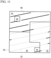
- a method of specifying the first region, the second region, and the third region is as follows. As illustrated in FIG. 10 , first, a virtual lattice L is set on the surface of the sample. As a result, the surface of the sample is divided into a plurality of cells C divided by the lattice L. The shape of the cell C is, for example, a square having a side of 2 mm. Then, the center of each of the cells C is used as a measurement point, and the crystal orientation is measured by a real side reflection Laue method. As a result, the ⁇ angle of the measurement point is specified, and it is determined whether the measurement point belongs to the first region A1, the second region A2, or the third region A3.
- the cell C whose center is determined to be the first region A1 is regarded as the first region A1 over the entire cell C.
- a cell C whose center is determined to be the second region A2 is regarded as the second region A2 over the entire cell C
- a cell C whose center is determined to be the third region A3 is regarded as the third region A3 over the entire cell C.
- the measurement point regarded as the first region A1 is indicated by a black circle P1
- the measurement point regarded as the second region A2 is indicated by a gray circle P2
- the measurement point regarded as the third region A3 is indicated by a black circle P3.
- the magnetic domain control treatment line 52 and the groove formation line 90 in each of the first region A1, the second region A2, and the third region A3 are specified by the procedure illustrated in the description of the method for measuring the angle formed by the magnetic domain control treatment line 52 and the orthogonal-to-rolling direction (TD).
- a value obtained by dividing the total length of all the groove formation lines 90 included in all the first regions A1 of the sample by all the magnetic domain control treatment lines 52 included in all the first regions A1 of the sample is the groove existence rate in the first region A1.
- the value obtained by dividing the total length of all the groove formation lines 90 included in all the second regions A2 of the sample by all the magnetic domain control treatment lines 52 included in all the second regions A2 of the sample is the groove existence rate in the second region A2
- the value obtained by dividing the total length of all the groove formation lines 90 included in all the third regions A3 of the sample by all the magnetic domain control treatment lines 52 included in all the third regions A3 of the sample is the groove existence rate in the third region A3.
- the method for measuring the interval of the groove formation line 90 along the rolling direction (RD) is as follows. First, the rolling direction (RD) and the groove formation line 90 are specified by the procedure described in the description of the method for measuring the angle formed by the magnetic domain control treatment line and the orthogonal-to-rolling direction (TD). Next, the interval between the groove formation lines 90 along the rolling direction (RD) may be measured.
- a method of determining whether the groove formation line 90 exists in a non-single period is as follows. First, the magnetic domain control treatment line 52 and the groove formation line 90 included in the sample are specified by the above-described procedure. As described above, it is assumed that the groove formation line 90 exists in a non-single period in the "the case where there are 10 or more groove formation lines 90 on average per 1 cm, and the standard deviation of the lengths of the non-magnetic domain refinement treatment lines between the groove formation lines 90 is more than 20 ⁇ m". Therefore, in the determination, it is determined whether each of the plurality of magnetic domain control treatment lines 52 included in the sample (for example, a rectangular sample with a length of 100 mm on both sides) includes 10 or more groove formation lines 90 on average per 1 cm.
- the length of one magnetic domain control treatment line 52 included in the sample is X cm and the number of groove formation lines 90 included in the magnetic domain control treatment line 52 is y, it is determined that there are y/X groove formation lines 90 on average per 1 cm in the magnetic domain control treatment line 52. Further, in each of the magnetic domain control treatment lines 52 determined to include 10 or more groove formation lines 90 on average per 1 cm, it is determined whether the standard deviation of the length of the non-magnetic domain refinement treatment line is 20 ⁇ m or less. When the groove formation line 90 is provided in a non-single period in 50% or more of all the magnetic domain control treatment lines 52 included in the sample, it is determined that the groove formation line 90 exists in the non-single period in the sample.
- the magnetic domain refinement treatment was performed under various conditions shown in Table 1 on the grain-oriented electrical steel sheets of the same lot which are classified as 23P085 in Table 2 of JIS C 2553:2019 "Grain-oriented electrical steel strip” and which have 0.23 mm of thickness.
- the noise and iron loss of the grain-oriented electrical steel sheets subjected to the magnetic domain refinement treatment obtained as a result are evaluated and described in Tables 2 and 3. In Table 2, inappropriate values were underlined.
- the methods for evaluating noise and iron loss were as follows. First, 180 grain-oriented electrical steel sheets having a sheet thickness of 0.23 mm were laminated to form a three-phase transformer core. The widths of the foot and the yoke of the three-phase transformer core were both 150 mm. The height and width of the outer shape of the three-phase transformer core were both 750 mm. Noise and iron loss of these three-phase transformer cores were measured. The measurement conditions were a frequency of 50 Hz and an excitation magnetic flux density of 1.5 T.
- the iron loss was obtained by measuring voltages and currents on the primary side and the secondary side with a power analyzer when excitation was performed at a frequency of 50 Hz and an excitation magnetic flux density of 1.5 T as described above.
- the obtained iron loss is described in Table 3 as an iron loss evaluation result (unit: W/kg) of the grain-oriented electrical steel sheet.
- the noise evaluation result determined to be unacceptable was underlined.
- the angle formed by the groove and the orthogonal-to-rolling direction, the depth of the groove, the width of the groove, the interval between the grooves, and the groove existence rate in the first region, the second region, or the third region were measured, and are described in Table 2.
- the groove was formed so that the angle formed by the groove and the orthogonal-to-rolling direction, the depth of the groove, the width of the groove, and the interval between the grooves are constant value.
- the measurement method was in principle according to the procedure described above. A rectangular sample having both sides of 100 mm in length was cut out from a three-phase transformer core for measuring noise and iron loss, and subjected to measurement.
- the groove existence rate is 0%.
- the groove existence ratio when the groove having inappropriate form was assumed as the groove formation line is described in Table 2.
- Example 1 the magnetic domain refinement treatment was not performed. In Example 1, since the groove formation line was not provided, deterioration of the noise evaluation result was not observed. On the other hand, in Example 1, iron loss reduction was not achieved.
- Example 2 the angle formed by the magnetic domain control treatment line and the orthogonal-to-rolling direction was excessive. In Example 2, the noise evaluation result deteriorated, but iron loss reduction was not achieved.
- Example 3 the depth of the groove was insufficient. In Example 3, iron loss reduction was not achieved. In Example 4, the depth of the groove was excessive. In Example 4, the noise evaluation result deteriorated, but iron loss reduction was not achieved.
- Example 5 the width of the groove was insufficient. In Example 5, iron loss reduction was not achieved. In Example 6, the width of the groove was excessive. In Example 6, the noise evaluation result deteriorated, but iron loss reduction was not achieved.
- Example 9 the groove was uniformly formed in the magnetic domain control treatment line.
- Example9 the groove existence rate in both the first region and the second region was set to a low level.
- noise was suppressed to a low level, on the other hand, iron loss reduction was not achieved.
- Example 10 the groove was uniformly formed in the magnetic domain control treatment line.
- the groove existence rate in both the first region and the second region was set to a high level.
- iron loss reduction was achieved, but noise reduction was not achieved.
- Example 7 Example 8, and Example 11 to Example 29
- the groove was preferentially formed to the point having the ⁇ angle of 1° or less.
- Example 7, Example 8, and Example 11 to Example 29 the form of the groove at the groove formation line was also within an appropriate range.
- both iron loss reduction and noise reduction were achieved.
- the iron loss and the noise were further reduced.
Landscapes
- Chemical & Material Sciences (AREA)
- Engineering & Computer Science (AREA)
- Physics & Mathematics (AREA)
- Materials Engineering (AREA)
- Organic Chemistry (AREA)
- Metallurgy (AREA)
- Mechanical Engineering (AREA)
- Power Engineering (AREA)
- Manufacturing & Machinery (AREA)
- Electromagnetism (AREA)
- Crystallography & Structural Chemistry (AREA)
- Thermal Sciences (AREA)
- Dispersion Chemistry (AREA)
- Manufacturing Of Steel Electrode Plates (AREA)
Applications Claiming Priority (2)
| Application Number | Priority Date | Filing Date | Title |
|---|---|---|---|
| JP2022052345 | 2022-03-28 | ||
| PCT/JP2023/012183 WO2023190331A1 (ja) | 2022-03-28 | 2023-03-27 | 方向性電磁鋼板及びその製造方法 |
Publications (2)
| Publication Number | Publication Date |
|---|---|
| EP4502189A1 true EP4502189A1 (de) | 2025-02-05 |
| EP4502189A4 EP4502189A4 (de) | 2025-07-16 |
Family
ID=88201724
Family Applications (1)
| Application Number | Title | Priority Date | Filing Date |
|---|---|---|---|
| EP23780341.6A Pending EP4502189A4 (de) | 2022-03-28 | 2023-03-27 | Kornorientierte magnetische stahlplatte und herstellungsverfahren dafür |
Country Status (6)
| Country | Link |
|---|---|
| US (1) | US20250118469A1 (de) |
| EP (1) | EP4502189A4 (de) |
| JP (1) | JP7828011B2 (de) |
| KR (1) | KR102857829B1 (de) |
| CN (1) | CN118647742A (de) |
| WO (1) | WO2023190331A1 (de) |
Families Citing this family (5)
| Publication number | Priority date | Publication date | Assignee | Title |
|---|---|---|---|---|
| WO2025070786A1 (ja) * | 2023-09-27 | 2025-04-03 | 日本製鉄株式会社 | 方向性電磁鋼板及びその製造方法 |
| JPWO2025070781A1 (de) * | 2023-09-27 | 2025-04-03 | ||
| JP7836023B2 (ja) * | 2023-09-27 | 2026-03-26 | 日本製鉄株式会社 | 方向性電磁鋼板及びその製造方法 |
| JPWO2025070776A1 (de) * | 2023-09-27 | 2025-04-03 | ||
| WO2025070780A1 (ja) * | 2023-09-27 | 2025-04-03 | 日本製鉄株式会社 | 方向性電磁鋼板、及び方向性電磁鋼板の製造方法 |
Family Cites Families (14)
| Publication number | Priority date | Publication date | Assignee | Title |
|---|---|---|---|---|
| JPS585969B2 (ja) * | 1979-03-05 | 1983-02-02 | 新日本製鐵株式会社 | 低鉄損一方向性珪素鋼板の製造方法 |
| JP3148092B2 (ja) | 1995-03-30 | 2001-03-19 | 新日本製鐵株式会社 | 鉄損の低い鏡面方向性電磁鋼板の製造方法 |
| JPH11293340A (ja) * | 1998-04-08 | 1999-10-26 | Kawasaki Steel Corp | 低鉄損方向性電磁鋼板及びその製造方法 |
| CN101946017B (zh) * | 2008-02-19 | 2013-06-05 | 新日铁住金株式会社 | 低铁损单向性电磁钢板的制造方法 |
| JP5691265B2 (ja) | 2010-06-30 | 2015-04-01 | Jfeスチール株式会社 | 方向性電磁鋼板の製造方法 |
| JP5668379B2 (ja) | 2010-09-09 | 2015-02-12 | Jfeスチール株式会社 | 方向性電磁鋼板およびその製造方法 |
| MX2013002627A (es) | 2010-09-10 | 2013-04-24 | Jfe Steel Corp | Lamina de acero magnetica de grano orientado y proceso para producir la misma. |
| JP5793859B2 (ja) | 2010-12-16 | 2015-10-14 | Jfeスチール株式会社 | 方向性電磁鋼板およびその製造方法 |
| EP2843069B1 (de) | 2012-04-26 | 2019-06-05 | JFE Steel Corporation | Kornorientiertes elektrisches stahlblech und verfahren zur herstellung davon |
| JP6176282B2 (ja) | 2014-04-11 | 2017-08-09 | Jfeスチール株式会社 | 方向性電磁鋼板およびその製造方法 |
| US20170298467A1 (en) | 2014-10-06 | 2017-10-19 | Jfe Steel Corporation | Low iron loss grain oriented electrical steel sheet and method for manufacturing the same |
| CN106282512B (zh) * | 2015-05-11 | 2018-03-30 | 宝山钢铁股份有限公司 | 低噪音变压器用取向硅钢片制造方法 |
| JP7319522B2 (ja) * | 2019-04-05 | 2023-08-02 | 日本製鉄株式会社 | 方向性電磁鋼板 |
| JP2022052345A (ja) | 2020-09-23 | 2022-04-04 | キヤノンメディカルシステムズ株式会社 | 超音波診断装置、撮像方法、及び撮像プログラム |
-
2023
- 2023-03-27 EP EP23780341.6A patent/EP4502189A4/de active Pending
- 2023-03-27 KR KR1020247025193A patent/KR102857829B1/ko active Active
- 2023-03-27 JP JP2024512453A patent/JP7828011B2/ja active Active
- 2023-03-27 CN CN202380019600.XA patent/CN118647742A/zh active Pending
- 2023-03-27 WO PCT/JP2023/012183 patent/WO2023190331A1/ja not_active Ceased
- 2023-03-27 US US18/729,419 patent/US20250118469A1/en active Pending
Also Published As
| Publication number | Publication date |
|---|---|
| JPWO2023190331A1 (de) | 2023-10-05 |
| JP7828011B2 (ja) | 2026-03-11 |
| KR20240129194A (ko) | 2024-08-27 |
| US20250118469A1 (en) | 2025-04-10 |
| EP4502189A4 (de) | 2025-07-16 |
| CN118647742A (zh) | 2024-09-13 |
| KR102857829B1 (ko) | 2025-09-10 |
| WO2023190331A1 (ja) | 2023-10-05 |
Similar Documents
| Publication | Publication Date | Title |
|---|---|---|
| EP4502189A1 (de) | Kornorientierte magnetische stahlplatte und herstellungsverfahren dafür | |
| EP4502190A1 (de) | Kornorientiertes elektromagnetisches stahlblech und verfahren zur herstellung davon | |
| EP4502188A1 (de) | Kornorientiertes elektrostahlblech und herstellungsverfahren dafür | |
| WO2025070780A1 (ja) | 方向性電磁鋼板、及び方向性電磁鋼板の製造方法 | |
| RU2840516C2 (ru) | Лист электротехнической стали с ориентированной зеренной структурой и способ его изготовления | |
| RU2841654C2 (ru) | Лист электротехнической стали с ориентированной зеренной структурой и способ его изготовления | |
| RU2846912C2 (ru) | Лист электротехнической стали с ориентированной зеренной структурой и способ его изготовления | |
| JP7817657B2 (ja) | 方向性電磁鋼板及びその製造方法 | |
| JP7836023B2 (ja) | 方向性電磁鋼板及びその製造方法 | |
| WO2025070785A1 (ja) | 方向性電磁鋼板 | |
| WO2025070790A1 (ja) | 方向性電磁鋼板、及び方向性電磁鋼板の製造方法 | |
| KR20260057131A (ko) | 방향성 전자 강판, 및 방향성 전자 강판의 제조 방법 | |
| WO2025070793A1 (ja) | 方向性電磁鋼板及びその製造方法 | |
| WO2025070786A1 (ja) | 方向性電磁鋼板及びその製造方法 | |
| WO2025070776A1 (ja) | 方向性電磁鋼板、及び方向性電磁鋼板の製造方法 | |
| KR20260057198A (ko) | 방향성 전자 강판, 및 방향성 전자 강판의 제조 방법 | |
| KR20260057212A (ko) | 방향성 전자 강판 및 그 제조 방법 | |
| KR20260057129A (ko) | 방향성 전자 강판 및 그 제조 방법 | |
| KR20260057119A (ko) | 방향성 전자 강판 및 그 제조 방법 | |
| KR20260057208A (ko) | 방향성 전자 강판, 및 방향성 전자 강판의 제조 방법 | |
| KR20260057118A (ko) | 방향성 전자 강판 및 방향성 전자 강판의 제조 방법 | |
| WO2025070781A1 (ja) | 方向性電磁鋼板、及び方向性電磁鋼板の製造方法 | |
| KR20260057218A (ko) | 방향성 전자 강판 및 그 제조 방법 |
Legal Events
| Date | Code | Title | Description |
|---|---|---|---|
| STAA | Information on the status of an ep patent application or granted ep patent |
Free format text: STATUS: THE INTERNATIONAL PUBLICATION HAS BEEN MADE |
|
| PUAI | Public reference made under article 153(3) epc to a published international application that has entered the european phase |
Free format text: ORIGINAL CODE: 0009012 |
|
| STAA | Information on the status of an ep patent application or granted ep patent |
Free format text: STATUS: REQUEST FOR EXAMINATION WAS MADE |
|
| 17P | Request for examination filed |
Effective date: 20240808 |
|
| AK | Designated contracting states |
Kind code of ref document: A1 Designated state(s): AL AT BE BG CH CY CZ DE DK EE ES FI FR GB GR HR HU IE IS IT LI LT LU LV MC ME MK MT NL NO PL PT RO RS SE SI SK SM TR |
|
| DAV | Request for validation of the european patent (deleted) | ||
| DAX | Request for extension of the european patent (deleted) | ||
| A4 | Supplementary search report drawn up and despatched |
Effective date: 20250613 |
|
| RIC1 | Information provided on ipc code assigned before grant |
Ipc: C21D 8/12 20060101AFI20250606BHEP Ipc: C21D 9/46 20060101ALI20250606BHEP Ipc: C22C 38/02 20060101ALI20250606BHEP Ipc: H01F 1/147 20060101ALI20250606BHEP Ipc: H01F 1/16 20060101ALI20250606BHEP Ipc: H01F 41/02 20060101ALI20250606BHEP |