EP4502314A2 - Système composite d'isolation thermique, façade dotée du système composite d'isolation thermique et procédé de construction associé - Google Patents
Système composite d'isolation thermique, façade dotée du système composite d'isolation thermique et procédé de construction associé Download PDFInfo
- Publication number
- EP4502314A2 EP4502314A2 EP24220605.0A EP24220605A EP4502314A2 EP 4502314 A2 EP4502314 A2 EP 4502314A2 EP 24220605 A EP24220605 A EP 24220605A EP 4502314 A2 EP4502314 A2 EP 4502314A2
- Authority
- EP
- European Patent Office
- Prior art keywords
- type
- base body
- anchor
- rod
- anchors
- Prior art date
- Legal status (The legal status is an assumption and is not a legal conclusion. Google has not performed a legal analysis and makes no representation as to the accuracy of the status listed.)
- Pending
Links
Images


Classifications
-
- E—FIXED CONSTRUCTIONS
- E04—BUILDING
- E04B—GENERAL BUILDING CONSTRUCTIONS; WALLS, e.g. PARTITIONS; ROOFS; FLOORS; CEILINGS; INSULATION OR OTHER PROTECTION OF BUILDINGS
- E04B1/00—Constructions in general; Structures which are not restricted either to walls, e.g. partitions, or floors or ceilings or roofs
- E04B1/62—Insulation or other protection; Elements or use of specified material therefor
- E04B1/74—Heat, sound or noise insulation, absorption, or reflection; Other building methods affording favourable thermal or acoustical conditions, e.g. accumulating of heat within walls
- E04B1/76—Heat, sound or noise insulation, absorption, or reflection; Other building methods affording favourable thermal or acoustical conditions, e.g. accumulating of heat within walls specifically with respect to heat only
- E04B1/762—Exterior insulation of exterior walls
- E04B1/7629—Details of the mechanical connection of the insulation to the wall
-
- B—PERFORMING OPERATIONS; TRANSPORTING
- B23—MACHINE TOOLS; METAL-WORKING NOT OTHERWISE PROVIDED FOR
- B23B—TURNING; BORING
- B23B49/00—Measuring or gauging equipment on boring machines for positioning or guiding the drill; Devices for indicating failure of drills during boring; Centering devices for holes to be bored
- B23B49/02—Boring templates or bushings
-
- E—FIXED CONSTRUCTIONS
- E04—BUILDING
- E04F—FINISHING WORK ON BUILDINGS, e.g. STAIRS, FLOORS
- E04F13/00—Coverings or linings, e.g. for walls or ceilings
- E04F13/02—Coverings or linings, e.g. for walls or ceilings of plastic materials hardening after applying, e.g. plaster
-
- E—FIXED CONSTRUCTIONS
- E04—BUILDING
- E04F—FINISHING WORK ON BUILDINGS, e.g. STAIRS, FLOORS
- E04F13/00—Coverings or linings, e.g. for walls or ceilings
- E04F13/07—Coverings or linings, e.g. for walls or ceilings composed of covering or lining elements; Sub-structures therefor; Fastening means therefor
- E04F13/08—Coverings or linings, e.g. for walls or ceilings composed of covering or lining elements; Sub-structures therefor; Fastening means therefor composed of a plurality of similar covering or lining elements
- E04F13/0875—Coverings or linings, e.g. for walls or ceilings composed of covering or lining elements; Sub-structures therefor; Fastening means therefor composed of a plurality of similar covering or lining elements having a basic insulating layer and at least one covering layer
Definitions
- This document relates to fastening means for a thermal insulation composite system, a facade with the thermal insulation composite system, as well as aids for installing the thermal insulation composite system and a method for installing the thermal insulation composite system.
- the building shell It is necessary to protect the shell of a building (hereinafter referred to as the building shell) against the effects of the weather.
- the building shell must also meet legal requirements for thermal insulation (and possibly also sound insulation).
- the building shell should also meet aesthetic requirements, at least in the visible part, also known as the facade.
- the building envelope is formed by facing brickwork or a layer of plaster.
- curtain walls in accordance with DIN EN 13830 (2003-11) ventilated facades in accordance with DIN 18516-1 and thermal insulation composite systems in accordance with DIN 55699 are increasingly used.
- curtain walls and ventilated facades usually have a support system that is different from the actual cladding (and in particular from plaster and/or reinforcing mesh), which is often in the form of battens and/or retaining profiles.
- This support system which is usually continuous horizontally and/or vertically across the entire facade, is either self-supporting or is fully or partially supported by the supporting structure. The support system then supports the actual cladding.
- This support system which is continuous horizontally and/or vertically across the entire facade, is missing in conventional thermal insulation composite systems.
- the cladding is supported by the supporting structure via the insulation material without an additional support system.
- the insulation material often has only a low load-bearing capacity on the side facing away from the supporting structure, depending on its thickness and the material used. Accordingly, the thickness of the cladding is often chosen to be so small that the cladding can just about be supported by the insulation material, but this is accompanied by a low compressive strength of the cladding.
- a thickness of the cladding that is so large that it is self-supporting, but this involves considerable use of materials and therefore costs.
- the thickness of the cladding must then be adapted to the height of the building.
- An example of such a self-supporting cladding is a brick wall placed in front of the insulation material.
- thermal insulation composite systems often require approval under building regulations.
- the object of the present invention to provide a thermal insulation composite system as well as aids and methods for constructing the same, which make it possible to provide a statically self-supporting cladding with little use of material. It is also the object of the present invention to provide a thermal insulation composite system as well as aids and methods for constructing the same, which make it possible to cover the cladding of the system in a variable manner and in particular with ceramic.
- a thermal insulation composite system comprises (any) insulation material, (facade) cladding and fastening means.
- the fastening means are designed to fasten the cladding to a supporting structure of a building in such a way that the insulation material is arranged between the cladding and the supporting structure on an outside of the building.
- the supporting structure itself is not part of the thermal insulation composite system.
- the fastening means comprise anchors of a first type. This designation was chosen in order to be able to distinguish the anchors of the first type from subsequently introduced anchors of a second type.
- Each anchor of the first type comprises one (optionally exactly one) rigid first base body and two (optionally exactly two) straight rods (each extending along a straight line over its entire length).
- the first base body has a first opening in a first section, which is assigned to a first rod of the two rods. Furthermore, the first base body has a second opening in a second section different from the first section, which is assigned to a second rod of the two rods. Surface normals to the first section and the second section of the first base body enclose an angle of between 10° and 30° or between 15° and 25° or 20°.
- the first base body is flat in the first and second sections, at least in the vicinity of the first and second openings.
- the first base body can also be flat throughout the entire first and second sections.
- the first base body therefore has an angled profile in cross-section.
- the edges around which the base body is angled can be parallel to one another.
- the first and second sections of the first base body thus define planes that intersect at an angle of between 10° and 30° or between 15° and 25° or 20°.
- the first bar and the second bar of the anchor of the first type can be identical or different.
- the two bars Since the first and second openings assigned to the two bars are formed in sections of the first base body that enclose a predetermined constant angle with each other, the two bars also enclose a predetermined constant angle with each other when assembled. This allows forces acting in different directions to be diverted in a defined manner using the anchor of the first type. As a result, a cladding held by the fastening means is statically self-supporting in itself (and thus independent of its height and independent of any insulation material used) (without the insulation material having to contribute to this). Since each square meter of cladding surface is thus independent of the surrounding cladding surface and independent of the insulation material itself, any large cladding areas can be provided without a static reassessment being necessary.
- the insulation material to be used can be chosen arbitrarily. Even in a case where the load-bearing capacity of the insulation material decreases over time (e.g. because the insulation material is partially removed by small animals or degenerates), this has no negative impact on the self-supporting properties of the cladding.
- the anchor of the first type further comprises a rigid second base body with an opening associated with the first rod.
- This second base body defines a single plane or planes parallel to one another and is thus not angled but is flat overall.
- the second base body can be a plate or disk or flat bowl with a hole (optionally in the middle).
- the bottom of the bowl and the edge of the bowl each define parallel planes.
- the fastening means further comprise anchors of a second type, each anchor of the second type comprising a (optionally exactly one) rigid third base body and a (optionally exactly one) straight third rod.
- the third base body has an opening which is assigned to the third rod.
- This third base body defines a plane or planes parallel to one another and is thus not angled, but flat.
- the third base body can be a plate or disc or flat bowl with a (optionally central) hole.
- the simultaneous use of both anchors of the first type and anchors of the second type has the advantage that the anchors of the second type can be attached more easily to the supporting structure of a building, since they only require one (third) rod.
- the anchors of the second type can be used primarily in the extension direction the associated third bars. Forces acting transversely to the direction of extension of the third bars can only be absorbed to the extent that the load-bearing capacity of the third bars in relation to the respective length of the third bars allows.
- the third bar of the second type anchor is identical in construction to the first and/or second bar of the first type anchor. However, it can also be different from the first and/or second bar.
- the rods of the anchors of the first type and/or the rods of the anchors of the second type are rigid.
- the fastening means comprise anchors of the first type and anchors of the second type per square meter of cladding surface in a ratio in which there are between two and eight anchors of the second type for each anchor of the first type, or between three and five anchors of the second type for each anchor of the first type, or four anchors of the second type for each anchor of the first type.
- a ratio makes it possible to transfer the forces typically acting on one square meter of cladding surface to the supporting structure to such an extent that the cladding surface is statically self-supporting, while at the same time ensuring that the cladding is sufficiently pressure-stable over its entire surface.
- the first, second and third base bodies of the anchors of the first and/or second type are made of sheet metal or deep-drawn sheet metal.
- Such base bodies can be manufactured inexpensively from a wide variety of sheets such as tinplate, galvanized sheet metal or stainless steel sheet metal.
- the strength of the respective base body can be adjusted so that the base body behaves like a rigid body when subjected to forces such as those to be expected during intended use.
- the first, second and third base bodies of the anchors of the first and/or second type can be connected in a force-fitting manner to the rods guided through the respective openings. This can be done, for example, by screwing, clamping or welding. It is also possible to provide the rods with a snap connector onto which the opening of a respective anchor can be plugged and which locks elastically after the anchor has been plugged in.
- the cladding comprises a reinforcing fabric which can be connected in a force-fitting manner to the anchors of the first and second type.
- a reinforcing fabric increases the surface stability of a cladding considerably. If the reinforcing fabric is also connected in a force-fitting manner to the anchors, the creation of a statically self-supporting cladding is made considerably easier, even if the cladding is of low thickness.
- the fastening means further comprise washers and screws or nuts.
- the washers and screws or nuts can be made of plastic or metal and in particular of stainless steel.
- a diameter of the washers is in each case larger than a mesh size of the reinforcing mesh.
- a diameter of the washers is in each case at least ten times or at least five times a mesh size of the reinforcing mesh.
- a diameter of the washers is smaller than a diameter of the second and/or third base bodies.
- a washer can be fastened to an anchor by means of a screw or nut in such a way that the reinforcing mesh is arranged between the second or third base body of the respective anchor and the washer.
- the screw or nut can be screwed directly to the anchor.
- the screw or nut can be screwed to a rod belonging to the anchor and the Washer can be connected indirectly to the anchor in this way.
- the washer can also be attached to the anchor or the rod using a snap connection on the anchor or on a rod belonging to the anchor.
- the reinforcing fabric is made of glass fibers or carbon fibers. Such fibers allow a high tensile load in relation to their weight.
- the reinforcing fabric has a mesh size of between 1 mm by 1 mm and 40 mm by 40 mm and in particular between 2 mm by 2 mm and 20 mm by 20 mm and further in particular between 3 mm by 3 mm and 10 mm by 10 mm.
- a nonwoven fabric can also be used as the reinforcing fabric.
- the cladding further comprises a reinforcing mortar in which the reinforcing fabric can be embedded.
- the layer thickness of the reinforcing mortar is between 5 mm and 30 mm or between 10 mm and 25 mm or between 15 mm and 20 mm.
- the reinforcing fabric is preferably embedded centrally in the reinforcing mortar.
- the cladding can then further comprise a ceramic covering which, after the reinforcing mortar has hardened, can be bonded to the latter in such a way that the reinforcing mortar is arranged between the ceramic covering and the insulation material.
- a ceramic covering is possible because the cladding forms a statically self-supporting surface in front of the insulation material, which is reliably held in place by the anchors.
- the thermal insulation composite system is free from a connection via the anchors of the first and/or second type and the insulation material additional support system for the reinforcing mesh and the reinforcing mortar.
- the (first, second and/or third) rods are threaded rods.
- the threaded rods can be screwed to dowels arranged in holes in the supporting structure.
- the dowels and/or rods are made of plastic to avoid cold bridges.
- the dowels and/or rods are made of metal and in particular of stainless steel.
- the rods have plastic sleeves screwed to the rods with two internal threads that are aligned with one another and separated from one another by a plastic wall.
- the first, second and/or third rods are rotationally symmetrical with the exception of a possible thread.
- the insulating material consists of vegetable, animal or mineral fibers, mineral foams or foamed plastics.
- the insulation material is glued to a supporting structure.
- a group of anchors of the second type is arranged along the circumference of a circle or a polygon or a regular polygon or a regular convex polygon and is connected to the supporting structure in a force-locking manner.
- the group of anchors of the second type comprises between two and eight anchors. If only two anchors of the second type are provided, these are arranged along a straight line.
- one anchor of the first type is arranged in the centroid of the circle or polygon, along the circumference of which the Anchors of the second type are arranged and connected to the structure in a force-locking manner. If only two anchors of the second type are provided, the anchor of the first type is arranged centrally between the anchors of the second type along a straight line connecting the anchors of the second type.
- adjacent anchors of the second type are spaced apart in the horizontal direction by a regular distance of between 20 cm and 80 cm or by a regular distance of between 40 cm and 60 cm or by a regular distance of 50 cm.
- adjacent anchors of the second type are spaced apart in the vertical direction by a regular distance of between 20 cm and 80 cm or by a regular distance of between 40 cm and 60 cm or by a regular distance of 50 cm.
- adjacent anchors of the first type are spaced apart in the horizontal direction by a regular distance of between 70 cm and 130 cm or by a regular distance of between 90 cm and 110 cm or by a regular distance of 100 cm.
- adjacent anchors of the first type are spaced apart in the vertical direction by a regular distance of between 70 cm and 130 cm or by a regular distance of between 90 cm and 110 cm or by a regular distance of 100 cm.
- a tool that can be used to create a facade with a thermal insulation composite system has a panel with a first flat side and a second flat side opposite the first flat side.
- the panel has two spaced-apart first and second openings that extend between the first and second flat sides and thus penetrate the plate in the direction of thickness.
- the openings can be holes, for example.
- the plate On the first flat side, the plate has a first hollow bar, the opening of which is aligned with the first opening.
- the first hollow bar forms a right angle with the first flat side.
- the plate On the second flat side, the plate has a second hollow bar, the opening of which is aligned with the second opening.
- the second hollow bar forms a smallest angle of between 60° and 80° or 70° with the second flat side.
- a free diameter of the first and second hollow bars is a maximum of 10 % greater than or equal to an outer diameter of the bars connected to the anchors of the first type.
- a length of the first hollow rod is between 0.5 cm and 2 cm and a length of the second hollow rod is between 5 cm and 15 cm or between 8 cm and 12 cm or 10 cm.
- a length of the second hollow rod is a multiple of the length of the first hollow rod.
- a distance between the first opening and the second opening is between 5 mm and 30 mm or between 10 mm and 20 mm. If the tool is used to produce a facade as described above, a distance between the first opening and the second opening in the plate of the tool is equal to the distance between the first opening and the second opening of the first base plate of the anchor of the first type.
- straight lines defined by the first hollow rod and the second hollow rod intersect.
- Embodiments of a method for producing a facade as described above using the aid described above comprise the following steps: Bonding (any) insulating material to a supporting structure. Drilling between two and eight holes of the first type per square meter through the insulating material into the supporting structure, the holes of the first type being oriented perpendicular to the supporting structure and arranged along the circumference of a circle or polygon or regular polygon or regular convex polygon; if only holes of the first type are provided, they are arranged along a straight line.
- Drilling one hole of the second type per square meter through the insulating material into the supporting structure the hole of the second type being oriented perpendicular to the supporting structure and arranged in the area of the centroid of the circle or polygon along whose circumference the holes of the first type are arranged; if only two holes of the first type are provided, the hole of the second type is arranged centrally between the holes of the first type along a straight line connecting the holes of the first type. Screwing straight rods into the holes of the first and second type in the supporting structure.
- a suitable dowel is previously arranged in the holes in the supporting structure.
- the first hollow rod of the tool over the rod screwed into the second type of hole in such a way that the second opening with the second hollow rod is arranged vertically below or above the first opening with the first hollow rod and the second hollow rod is arranged on the flat side of the tool facing away from the insulation material.
- a suitable dowel is previously arranged in the holes in the supporting structure.
- this force-fitting connection is carried out by screwing or by welding or by a snap connection.
- the insulating material and the reinforcing mortar are thus adapted to one another in such a way that the insulating material can carry the first layer of reinforcing mortar.
- this force-fitting fastening is carried out by screwing or by welding or by a snap connection.
- this force-fitting fastening is carried out using second and third base bodies and washers, the reinforcing fabric being arranged between the second and third base bodies and a washer in each case. Then the diameter of the washer is larger than the mesh size of the reinforcing mesh and is adapted to the diameter of the second and third base body.
- the method further comprises bonding a ceramic covering to the second layer of reinforcing mortar after the reinforcing mortar has hardened.
- the method further comprises bonding a covering made of wood, natural stone, artificial stone, metal sheet or glass to the second layer of reinforcing mortar after the reinforcing mortar has hardened.
- the covering is then grouted.
- the facade 1 consists of insulation material 2 glued to a supporting structure 4 and a (facade) cladding 3, which is held by anchors A1, A2.
- the supporting structure 4 is a solid outer wall of a building made of concrete and the insulating material 2 is a block of mineral wool.
- the thickness of the insulating material 2 and thus the distance between the cladding 3 and the supporting structure 4 is 20 cm.
- the thickness and type of insulating material 3 used is of secondary importance for the cladding according to the invention, so that any insulating material with any thickness can be used.
- anchors of a first type A1 and anchors of a second type A2 are used to make the cladding statically self-supporting.
- the anchors of the first type A1 are characterized in that they have first and second rods 51 and 56, which are force-lockingly connected via a rigid first base body 55.
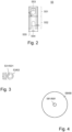
- the rigid first base body 55 which in the embodiment shown is an elongated strip of stainless steel sheet with a thickness of 2 mm, is in Figure 2 shown in top view.
- the rigid first base body 55 is folded along two spaced apart and parallel bending edges K1, K2.
- the bending edges thus form two sections 551 and 552 within which the first base body 55 is flat.
- Both sections 551, 552 each have openings 553, 554.
- a first opening 553 in the first section 551 has a hexagonal opening cross-section and is thus closed in the circumferential direction
- a second opening 554 in the second section 552 is a recess open to an end face 555 of the first base body 55.
- first and second sections 551, 552 of the first base body 55 enclose an angle of 20° with one another in the embodiment shown. Furthermore, the first and second openings 553, 554 in the embodiment shown are arranged in the first base body 55 such that surface normals to the first and second sections 551, 552 intersect in the region of the first and second openings 553, 554.
- a tool attack of a plastic sleeve 59 of the first rod 51 penetrates the first opening 553 in the first section 551 of the first base body 55 such that the first rod 51 is perpendicular to the first section 551.
- the second rod 56 penetrates the second opening 554 in the second section 552 of the first base body 55 such that the second rod 56 is perpendicular to the second section 552. Due to the multiple folding of the first base body 55, the two first and second rods 51, 56 then also form an angle of 20° with one another.
- the first rod 51 is screwed to the supporting structure 4 in a bore B2 in such a way that it is oriented perpendicularly to the supporting structure 4.
- the second rod 56 is screwed to the supporting structure 4 in a bore B3 in such a way that it forms an angle ⁇ of 70° with the supporting structure 4.
- the first and second rods 51, 56 of the anchor of the first type A1 thus form a triangle which is capable of absorbing forces acting on the first base body 55 perpendicularly to the supporting structure 4 as well as in the vertical direction of Figure 1 to dissipate forces acting on the first base body 55.
- first and second rods 51, 56 are each threaded rods made of stainless steel with an outer diameter of 10 mm, which are connected to the supporting structure 4 via threaded rods inserted into bores B2, B3 (in Figure 1 dowels (not shown) are connected to the supporting structure 4.
- first and second bars 51, 56 each penetrate 7 cm into the supporting structure 4.
- the first rod 51 in the embodiment shown has a cylindrical plastic sleeve 59 at its end not connected to the supporting structure 4, which has two internal threads that are aligned with one another and separated from one another by a plastic wall. One of the internal threads is screwed onto the first rod 51.
- the plastic sleeve 59 has a tool grip with a hexagonal cross-section that surrounds the other internal thread. This tool grip passes through the first opening 553 in the first section 551 of the first base body 55.
- Rods with such plastic sleeves can be purchased under the name "Thermax” (registered trademark) 12/16 spacing system from fischerwerke GmbH & Co. KG, Klaus-Fischer-Strckee 1, 72178 Waldachtal, Germany.
- the spacer 53 shown on the left in side view and on the right in plan view is placed on the spacer 53, which also has an opening 531 with a hexagonal cross section.
- the spacer 53 carries a Figure 4
- the second base body 58 shown in plan view is made of 1 mm thick stainless steel sheet with a centrally arranged opening 581 in the form of a hole.
- the second Base body 58 has the shape of a flat, rigid bowl-shaped disc with a 4 mm high rim.
- the length of the first and second rods 51, 56 is adapted to the material thickness of the insulating material 2 such that the first base body 55 is embedded in the insulating material 2 and the second base body 58 rests flush on the insulating material 2 without pressure.
- a first layer of reinforcing mortar 32 with a thickness of 5 mm is arranged on the insulation material 2, which carries a reinforcing mesh 31.
- the reinforcing mortar 32 is Sopro renovation and leveling mortar " RAM 3" (registered trademark) and the reinforcing mesh 31 is glass fiber mesh available under the name "Sopro PanzerGewebe eXtra - PG-X 1188" . Both products are available from Sopro Bauchemie GmbH in 65102 Wiesbaden. Instead of a glass fiber mesh, a carbon fiber mat can also be used, for example.
- a stainless steel screw 52 is screwed into the second internal thread of the plastic sleeve 59 facing away from the first rod 51, which screw passes through a cap-shaped washer 54 and the reinforcing fabric 31 and thus holds the reinforcing fabric 31 between the second base body 58 and the washer 54. It can be seen that the diameters of the second base body 58 and the washer 54 are considerably larger than a mesh size of the reinforcing fabric 31 and are adapted to one another in such a way that a diameter of the washer 54 is smaller than a diameter of the second base body 58.
- the free end of the second rod 56 facing away from the supporting structure 4 is inserted into the second opening 554 in the first base body 55 and is connected to the base body 55 by means of two nuts 57. It is designed to prevent However, it is optionally possible to use a plastic sleeve here as well, as is provided for the first rod 51.
- the in Figure 1 The facade 1 shown further has an anchor of a second type A2.
- the anchor of the second type A2 has a third rod 61 in the form of a threaded rod which is screwed vertically 7 cm deep to the supporting structure 4 via a bore B1 and has a plastic sleeve at its free end, as is also provided for the first rod 51.
- the plastic sleeve carries a third base body 68 made of 1 mm thick stainless steel sheet in the form of a flat, rigid, bowl-shaped disk with a 4 mm high edge with a centrally arranged opening 681 in the form of a bore.
- a stainless steel screw 62 is screwed into the second internal thread of the plastic sleeve facing away from the third rod 61, which passes through a cap-shaped washer 64 and the reinforcing mesh 31 and thus holds the reinforcing mesh 31 between the third base body 68 and the washer 64.
- the third rod 61, the plastic sleeve, the spacer 63, the third base body 68, the stainless steel screw 62 and the washer 64 are constructed identically to the first rod 51 with the associated plastic sleeve, the spacer 53, the second base body 58, the stainless steel screw 52 and the washer 54, so reference is made to what has been said above.
- a second layer of reinforcing mortar 32 with a thickness of 15 mm is arranged on the reinforcing mesh 31, in which the stainless steel screws 52, 62 and the cap-shaped washers 54, 64 are embedded and which carries a ceramic covering 33 in the form of tiles via a tile adhesive (not shown).
- any insulation material 3 is glued to the supporting structure 4.
- Anchors for the (facade) cladding must then be installed.
- the required ratio depends in particular on the specific design of the cladding and therefore on the question of whether the cladding is to support a ceramic covering, for example, or not.
- the load-bearing capacity of the insulation material plays a minor role at best.
- four anchors of the second type A2 per anchor of the first type A1 have proven to be sufficient.
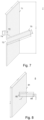
- Figure 5 provides the construction of the facade Figure 1 after bonding the insulation material 3 to the supporting structure 4, the holes are shown schematically.
- the square boxes in dashed lines each indicate one square meter of facade area.
- holes of the first type B1 are drilled into the insulation material 3 and the supporting structure 4 per square meter of facade area. These holes are each arranged in the corners of a square with an edge length of 50 cm.
- the aid 8 consists of a flat square plate 81 with a side length of 20 cm, which has a central penetration 82. Perpendicular to the plate 81 is a hollow rod 84 provided, the opening of which is aligned with the penetration 82 in the plate 81. Plate 81 and hollow rod 82 are made of metal. The plate 81 of the aid 8 is placed flat on the insulation material 3 in the desired position. The hollow rod 82 can then be used as a guide for a drill (not shown).
- a second type of hole B2 is then placed in the area center of the square defined by the first type of hole B1.
- the second type of hole B2 is then arranged in the corners of squares with a side length of 100 cm. Since the second type of hole B2 should also be oriented perpendicular to the supporting structure 4, the aid 8 can be used for this.
- the first and third rods 51, 61 are then screwed to the supporting structure 4, for which purpose dowels can first be inserted into the supporting structure 4.
- the first and third rods 51, 61 each have a plastic sleeve 59, 69 with a hexagonal tool attachment at their free end.
- the further aid 7 consists of a flat rectangular plate 71, which has two opposite, parallel first and second flat sides.
- the plate 71 has two first and second openings 72, 73, spaced 20 mm apart from each other.
- the plate 71 On the first flat side, the plate 71 has a 10 mm long first hollow rod 74, the opening of which is aligned with the first opening 72.
- the plate 71 On the opposite second flat side, the plate 71 has a 10 cm long second hollow rod 75, the opening of which is aligned with the second opening 73.
- the first hollow rod 74 and the second hollow rod 75 are oriented so that the first hollow rod 74 forms a right angle with the first flat side, and the second hollow rod 75 forms a smallest angle of 70° with the second flat side and straight lines defined by the first and second hollow rods 74, 75 intersect.
- a free cross section of the first hollow rod 74 is adapted to the tool attack of the plastic sleeve.
- the first hollow rod 74 of the further aid 8 is placed on the tool attachment of the plastic sleeve 59 screwed to the first rod 51 in such a way that the plate 71 lies flat on the insulation material 3 and the second hollow rod 74 is arranged vertically above or below the first opening 72.
- the second hollow rod 74 can then be used as a guide for a drill (not shown).
- the third type of holes B3 also form a smallest angle of 70° with the supporting structure 4.
- the second rods 56 are screwed to the supporting structure 4, for which dowels can first be inserted into the supporting structure 4.
- the first opening 553 of the first base body 55 can be pushed onto the tool attachment of the plastic sleeve screwed to the first rod 51 so that the second rod 56 is arranged in the second opening 554 of the first base body 55.
- the first base body 55 can then be connected to the second rod 56 in a force-fitting manner using the nuts 57.
- spacers 53, 63 are placed on the tool grips of the plastic sleeves 59, 69 screwed to the first and third rods 51, 61 and a first layer of reinforcing mortar 32 with a layer thickness of 5 mm is applied to the insulation material 2.
- the second and third base bodies 58, 68 and a reinforcing mesh 31 are arranged adjacent to the still fresh first layer of reinforcing mortar 32.
- the reinforcing mesh 31 is fastened to the anchors of the first and second type A1, A2 by means of the screws 52, 62 and washers 54, 64 via the plastic sleeves 59, 69, before a second layer of reinforcing mortar 32 with a layer thickness of 10 mm is applied to the still fresh first layer of reinforcing mortar 32 in such a way that the screws 52, 62 and washers 54, 64 are completely embedded in the reinforcing mortar 32. This is shown schematically in Figure 6 shown.
- the (facade) cladding 1 thus formed is statically self-supporting and can be covered with a ceramic covering 33 using a suitable tile adhesive (not shown).
- a suitable tile adhesive can be obtained under the name "megaFlex TX - MEG 667" from Sopro Bauchemie GmbH in 65102 Wiesbaden.
Landscapes
- Engineering & Computer Science (AREA)
- Architecture (AREA)
- Civil Engineering (AREA)
- Structural Engineering (AREA)
- Physics & Mathematics (AREA)
- Mechanical Engineering (AREA)
- Acoustics & Sound (AREA)
- Electromagnetism (AREA)
- Building Environments (AREA)
Applications Claiming Priority (2)
| Application Number | Priority Date | Filing Date | Title |
|---|---|---|---|
| DE202020103522.3U DE202020103522U1 (de) | 2020-06-18 | 2020-06-18 | Wärmedämmverbundsystem, Fassade mit dem Wärmedämmverbundsystem sowie Hilfsmittel zur Errichtung desselben |
| EP21178515.9A EP3926117B1 (fr) | 2020-06-18 | 2021-06-09 | Système composite d'isolation thermique, façade pourvue de système composite d'isolation thermique, ainsi que son procédé de construction |
Related Parent Applications (2)
| Application Number | Title | Priority Date | Filing Date |
|---|---|---|---|
| EP21178515.9A Division EP3926117B1 (fr) | 2020-06-18 | 2021-06-09 | Système composite d'isolation thermique, façade pourvue de système composite d'isolation thermique, ainsi que son procédé de construction |
| EP21178515.9A Division-Into EP3926117B1 (fr) | 2020-06-18 | 2021-06-09 | Système composite d'isolation thermique, façade pourvue de système composite d'isolation thermique, ainsi que son procédé de construction |
Publications (2)
| Publication Number | Publication Date |
|---|---|
| EP4502314A2 true EP4502314A2 (fr) | 2025-02-05 |
| EP4502314A3 EP4502314A3 (fr) | 2025-04-23 |
Family
ID=76355390
Family Applications (2)
| Application Number | Title | Priority Date | Filing Date |
|---|---|---|---|
| EP21178515.9A Active EP3926117B1 (fr) | 2020-06-18 | 2021-06-09 | Système composite d'isolation thermique, façade pourvue de système composite d'isolation thermique, ainsi que son procédé de construction |
| EP24220605.0A Pending EP4502314A3 (fr) | 2020-06-18 | 2021-06-09 | Système composite d'isolation thermique, façade dotée du système composite d'isolation thermique et procédé de construction associé |
Family Applications Before (1)
| Application Number | Title | Priority Date | Filing Date |
|---|---|---|---|
| EP21178515.9A Active EP3926117B1 (fr) | 2020-06-18 | 2021-06-09 | Système composite d'isolation thermique, façade pourvue de système composite d'isolation thermique, ainsi que son procédé de construction |
Country Status (3)
| Country | Link |
|---|---|
| EP (2) | EP3926117B1 (fr) |
| DE (1) | DE202020103522U1 (fr) |
| PL (1) | PL3926117T3 (fr) |
Families Citing this family (1)
| Publication number | Priority date | Publication date | Assignee | Title |
|---|---|---|---|---|
| CN119877799A (zh) * | 2024-12-30 | 2025-04-25 | 中建科工集团有限公司 | 一种外墙抹灰施工工艺 |
Citations (1)
| Publication number | Priority date | Publication date | Assignee | Title |
|---|---|---|---|---|
| US20050278934A1 (en) * | 2004-03-19 | 2005-12-22 | Brian Orchard | Device and method for fastening structural members |
Family Cites Families (4)
| Publication number | Priority date | Publication date | Assignee | Title |
|---|---|---|---|---|
| DE29920332U1 (de) * | 1999-11-19 | 2000-03-30 | Alsecco Bauchemische Produkte GmbH & Co. KG, 36208 Wildeck | Vorrichtung zum Befestigen wenigsens eines Bauteiles auf einem Wärmedämmverbundsystem |
| DE102008053638A1 (de) * | 2008-10-30 | 2010-06-10 | Rensburg, Markus, Dipl.-Wirtsch.-Ing. | Vorrichtung zum Justieren eines Bauelementes in einem Abstand zum Bauteil |
| WO2012143035A1 (fr) * | 2011-04-18 | 2012-10-26 | Fibrecem Holding Ag | Tôle de renforcement |
| DE102011102510A1 (de) * | 2011-05-26 | 2012-11-29 | Sfs Intec Holding Ag | System zum Befestigen einer Dämmfassade und dafür vorgesehener Befestiger |
-
2020
- 2020-06-18 DE DE202020103522.3U patent/DE202020103522U1/de active Active
-
2021
- 2021-06-09 PL PL21178515.9T patent/PL3926117T3/pl unknown
- 2021-06-09 EP EP21178515.9A patent/EP3926117B1/fr active Active
- 2021-06-09 EP EP24220605.0A patent/EP4502314A3/fr active Pending
Patent Citations (1)
| Publication number | Priority date | Publication date | Assignee | Title |
|---|---|---|---|---|
| US20050278934A1 (en) * | 2004-03-19 | 2005-12-22 | Brian Orchard | Device and method for fastening structural members |
Also Published As
| Publication number | Publication date |
|---|---|
| EP4502314A3 (fr) | 2025-04-23 |
| EP3926117B1 (fr) | 2025-02-19 |
| DE202020103522U1 (de) | 2021-08-25 |
| PL3926117T3 (pl) | 2025-10-27 |
| EP3926117A1 (fr) | 2021-12-22 |
| EP3926117C0 (fr) | 2025-02-19 |
Similar Documents
| Publication | Publication Date | Title |
|---|---|---|
| CH637724A5 (de) | Isolierte aussenbekleidung fuer gebaeudewaende. | |
| EP2722466B1 (fr) | Système composite destiné à renforcer des éléments de construction | |
| DE19828607A1 (de) | Verfahren zum Verstärken von Stahl- und Spannbetonbauteilen | |
| EP2715013A1 (fr) | Ensemble d'assemblage et procédé de production d'une consolidation contre la perforation, d'un renfort de force transversale supplémentaire ou d'un raccordement d'armature | |
| EP3926117B1 (fr) | Système composite d'isolation thermique, façade pourvue de système composite d'isolation thermique, ainsi que son procédé de construction | |
| EP1953303B1 (fr) | Elément de construction mural, procédé de fabrication d'un élément de construction mural et dispositif d'ancre pour un élément de construction mural | |
| DE102007004573B4 (de) | Wandbauelement und Verfahren zur Herstellung eines Wandbauelements | |
| EP1842984B1 (fr) | Plaque de coffrage profilée de bordure de dalle en béton | |
| DE102020116153A1 (de) | Wärmedämmverbundsystem, Fassade mit dem Wärmedämmverbundsystem sowie Hifsmittel und Verfahren zur Errichtung desselben | |
| DE102005040388A1 (de) | Stützverbund für Gebäude sowie Teile zu seiner Herstellung | |
| DE10066165B4 (de) | Wärmedämmverbundsystem sowie bandförmiges Element für die Befestigung von Dämmstoffelementen | |
| EP3024992B1 (fr) | Système de fixation d'éléments isolants | |
| DE102016103981B4 (de) | Schalungselement | |
| EP2733272B1 (fr) | Systèmes composites d'isolation thermique pour façades de bâtiment | |
| DE102014119132B4 (de) | Fliese und Verfahren zur Verlegung mehrerer derartiger Fliesen | |
| DE2263027A1 (de) | Aus kurzen holzteilen zusammengesetztes bauteil | |
| DE4101133C2 (de) | Verfahren zur Befestigung von Bahnen an Holzwolle-Leichtbauplatten | |
| DE202015105915U1 (de) | Modulhaus | |
| DE102022119025A1 (de) | Befestigungssystem für ein Fassadenelement und Verfahren zur Befestigung bei auskragender Geschoßdecke | |
| DE10241231A1 (de) | Wärme- und/oder Schalldämmsystem sowie Dämmelement | |
| WO2003076735A1 (fr) | Systeme d'isolation thermique et/ou acoustique et element isolant | |
| CH718011B1 (de) | Konstruktionssystem für die Errichtung von Mauerwerken im Hoch- und Tiefbau. | |
| DE10219504A1 (de) | Dämmstoffplatte | |
| DE102007004572A1 (de) | Wandbauelement, Verfahren zur Herstellung eines Wandbauelements und eine Bewehrungsmatte für ein Wandbauelement | |
| DE1816892U (de) | Hohles bauelement, z. b. hohlziegel und daraus gefertigte bauplatte. |
Legal Events
| Date | Code | Title | Description |
|---|---|---|---|
| PUAI | Public reference made under article 153(3) epc to a published international application that has entered the european phase |
Free format text: ORIGINAL CODE: 0009012 |
|
| STAA | Information on the status of an ep patent application or granted ep patent |
Free format text: STATUS: THE APPLICATION HAS BEEN PUBLISHED |
|
| AC | Divisional application: reference to earlier application |
Ref document number: 3926117 Country of ref document: EP Kind code of ref document: P |
|
| AK | Designated contracting states |
Kind code of ref document: A2 Designated state(s): AL AT BE BG CH CY CZ DE DK EE ES FI FR GB GR HR HU IE IS IT LI LT LU LV MC MK MT NL NO PL PT RO RS SE SI SK SM TR |
|
| REG | Reference to a national code |
Ref country code: DE Ref legal event code: R079 Free format text: PREVIOUS MAIN CLASS: E04F0013080000 Ipc: E04B0001760000 |
|
| PUAL | Search report despatched |
Free format text: ORIGINAL CODE: 0009013 |
|
| AK | Designated contracting states |
Kind code of ref document: A3 Designated state(s): AL AT BE BG CH CY CZ DE DK EE ES FI FR GB GR HR HU IE IS IT LI LT LU LV MC MK MT NL NO PL PT RO RS SE SI SK SM TR |
|
| RIC1 | Information provided on ipc code assigned before grant |
Ipc: E04F 13/08 20060101ALI20250317BHEP Ipc: B23B 49/02 20060101ALI20250317BHEP Ipc: E04B 1/76 20060101AFI20250317BHEP |
|
| STAA | Information on the status of an ep patent application or granted ep patent |
Free format text: STATUS: REQUEST FOR EXAMINATION WAS MADE |
|
| 17P | Request for examination filed |
Effective date: 20250812 |
|
| GRAP | Despatch of communication of intention to grant a patent |
Free format text: ORIGINAL CODE: EPIDOSNIGR1 |
|
| STAA | Information on the status of an ep patent application or granted ep patent |
Free format text: STATUS: GRANT OF PATENT IS INTENDED |
|
| INTG | Intention to grant announced |
Effective date: 20260325 |