EP4502372A1 - Hauptlagereinheit - Google Patents
Hauptlagereinheit Download PDFInfo
- Publication number
- EP4502372A1 EP4502372A1 EP23189135.9A EP23189135A EP4502372A1 EP 4502372 A1 EP4502372 A1 EP 4502372A1 EP 23189135 A EP23189135 A EP 23189135A EP 4502372 A1 EP4502372 A1 EP 4502372A1
- Authority
- EP
- European Patent Office
- Prior art keywords
- preload
- bearing
- housing
- ring
- preload ring
- Prior art date
- Legal status (The legal status is an assumption and is not a legal conclusion. Google has not performed a legal analysis and makes no representation as to the accuracy of the status listed.)
- Withdrawn
Links
Images


Classifications
-
- F—MECHANICAL ENGINEERING; LIGHTING; HEATING; WEAPONS; BLASTING
- F16—ENGINEERING ELEMENTS AND UNITS; GENERAL MEASURES FOR PRODUCING AND MAINTAINING EFFECTIVE FUNCTIONING OF MACHINES OR INSTALLATIONS; THERMAL INSULATION IN GENERAL
- F16C—SHAFTS; FLEXIBLE SHAFTS; ELEMENTS OR CRANKSHAFT MECHANISMS; ROTARY BODIES OTHER THAN GEARING ELEMENTS; BEARINGS
- F16C25/00—Bearings for exclusively rotary movement adjustable for wear or play
- F16C25/06—Ball or roller bearings
-
- F—MECHANICAL ENGINEERING; LIGHTING; HEATING; WEAPONS; BLASTING
- F03—MACHINES OR ENGINES FOR LIQUIDS; WIND, SPRING, OR WEIGHT MOTORS; PRODUCING MECHANICAL POWER OR A REACTIVE PROPULSIVE THRUST, NOT OTHERWISE PROVIDED FOR
- F03D—WIND MOTORS
- F03D80/00—Details, components or accessories not provided for in groups F03D1/00 - F03D17/00
- F03D80/70—Bearing or lubricating arrangements
- F03D80/703—Shaft bearings
-
- F—MECHANICAL ENGINEERING; LIGHTING; HEATING; WEAPONS; BLASTING
- F16—ENGINEERING ELEMENTS AND UNITS; GENERAL MEASURES FOR PRODUCING AND MAINTAINING EFFECTIVE FUNCTIONING OF MACHINES OR INSTALLATIONS; THERMAL INSULATION IN GENERAL
- F16C—SHAFTS; FLEXIBLE SHAFTS; ELEMENTS OR CRANKSHAFT MECHANISMS; ROTARY BODIES OTHER THAN GEARING ELEMENTS; BEARINGS
- F16C25/00—Bearings for exclusively rotary movement adjustable for wear or play
- F16C25/06—Ball or roller bearings
- F16C25/08—Ball or roller bearings self-adjusting
- F16C25/083—Ball or roller bearings self-adjusting with resilient means acting axially on a race ring to preload the bearing
-
- F—MECHANICAL ENGINEERING; LIGHTING; HEATING; WEAPONS; BLASTING
- F16—ENGINEERING ELEMENTS AND UNITS; GENERAL MEASURES FOR PRODUCING AND MAINTAINING EFFECTIVE FUNCTIONING OF MACHINES OR INSTALLATIONS; THERMAL INSULATION IN GENERAL
- F16C—SHAFTS; FLEXIBLE SHAFTS; ELEMENTS OR CRANKSHAFT MECHANISMS; ROTARY BODIES OTHER THAN GEARING ELEMENTS; BEARINGS
- F16C35/00—Rigid support of bearing units; Housings, e.g. caps, covers
- F16C35/04—Rigid support of bearing units; Housings, e.g. caps, covers in the case of ball or roller bearings
- F16C35/06—Mounting or dismounting of ball or roller bearings; Fixing them onto shaft or in housing
- F16C35/07—Fixing them on the shaft or housing with interposition of an element
- F16C35/077—Fixing them on the shaft or housing with interposition of an element between housing and outer race ring
-
- F—MECHANICAL ENGINEERING; LIGHTING; HEATING; WEAPONS; BLASTING
- F16—ENGINEERING ELEMENTS AND UNITS; GENERAL MEASURES FOR PRODUCING AND MAINTAINING EFFECTIVE FUNCTIONING OF MACHINES OR INSTALLATIONS; THERMAL INSULATION IN GENERAL
- F16C—SHAFTS; FLEXIBLE SHAFTS; ELEMENTS OR CRANKSHAFT MECHANISMS; ROTARY BODIES OTHER THAN GEARING ELEMENTS; BEARINGS
- F16C39/00—Relieving load on bearings
- F16C39/04—Relieving load on bearings using hydraulic or pneumatic means
-
- F—MECHANICAL ENGINEERING; LIGHTING; HEATING; WEAPONS; BLASTING
- F05—INDEXING SCHEMES RELATING TO ENGINES OR PUMPS IN VARIOUS SUBCLASSES OF CLASSES F01-F04
- F05B—INDEXING SCHEME RELATING TO WIND, SPRING, WEIGHT, INERTIA OR LIKE MOTORS, TO MACHINES OR ENGINES FOR LIQUIDS COVERED BY SUBCLASSES F03B, F03D AND F03G
- F05B2240/00—Components
- F05B2240/50—Bearings
- F05B2240/54—Radial bearings
-
- F—MECHANICAL ENGINEERING; LIGHTING; HEATING; WEAPONS; BLASTING
- F16—ENGINEERING ELEMENTS AND UNITS; GENERAL MEASURES FOR PRODUCING AND MAINTAINING EFFECTIVE FUNCTIONING OF MACHINES OR INSTALLATIONS; THERMAL INSULATION IN GENERAL
- F16C—SHAFTS; FLEXIBLE SHAFTS; ELEMENTS OR CRANKSHAFT MECHANISMS; ROTARY BODIES OTHER THAN GEARING ELEMENTS; BEARINGS
- F16C2229/00—Setting preload
-
- F—MECHANICAL ENGINEERING; LIGHTING; HEATING; WEAPONS; BLASTING
- F16—ENGINEERING ELEMENTS AND UNITS; GENERAL MEASURES FOR PRODUCING AND MAINTAINING EFFECTIVE FUNCTIONING OF MACHINES OR INSTALLATIONS; THERMAL INSULATION IN GENERAL
- F16C—SHAFTS; FLEXIBLE SHAFTS; ELEMENTS OR CRANKSHAFT MECHANISMS; ROTARY BODIES OTHER THAN GEARING ELEMENTS; BEARINGS
- F16C2360/00—Engines or pumps
- F16C2360/31—Wind motors
-
- F—MECHANICAL ENGINEERING; LIGHTING; HEATING; WEAPONS; BLASTING
- F16—ENGINEERING ELEMENTS AND UNITS; GENERAL MEASURES FOR PRODUCING AND MAINTAINING EFFECTIVE FUNCTIONING OF MACHINES OR INSTALLATIONS; THERMAL INSULATION IN GENERAL
- F16C—SHAFTS; FLEXIBLE SHAFTS; ELEMENTS OR CRANKSHAFT MECHANISMS; ROTARY BODIES OTHER THAN GEARING ELEMENTS; BEARINGS
- F16C35/00—Rigid support of bearing units; Housings, e.g. caps, covers
- F16C35/04—Rigid support of bearing units; Housings, e.g. caps, covers in the case of ball or roller bearings
- F16C35/06—Mounting or dismounting of ball or roller bearings; Fixing them onto shaft or in housing
- F16C35/062—Dismounting of ball or roller bearings
-
- F—MECHANICAL ENGINEERING; LIGHTING; HEATING; WEAPONS; BLASTING
- F16—ENGINEERING ELEMENTS AND UNITS; GENERAL MEASURES FOR PRODUCING AND MAINTAINING EFFECTIVE FUNCTIONING OF MACHINES OR INSTALLATIONS; THERMAL INSULATION IN GENERAL
- F16C—SHAFTS; FLEXIBLE SHAFTS; ELEMENTS OR CRANKSHAFT MECHANISMS; ROTARY BODIES OTHER THAN GEARING ELEMENTS; BEARINGS
- F16C41/00—Other accessories, e.g. devices integrated in the bearing not relating to the bearing function as such
- F16C41/005—Fluid passages not relating to lubrication or cooling
-
- Y—GENERAL TAGGING OF NEW TECHNOLOGICAL DEVELOPMENTS; GENERAL TAGGING OF CROSS-SECTIONAL TECHNOLOGIES SPANNING OVER SEVERAL SECTIONS OF THE IPC; TECHNICAL SUBJECTS COVERED BY FORMER USPC CROSS-REFERENCE ART COLLECTIONS [XRACs] AND DIGESTS
- Y02—TECHNOLOGIES OR APPLICATIONS FOR MITIGATION OR ADAPTATION AGAINST CLIMATE CHANGE
- Y02E—REDUCTION OF GREENHOUSE GAS [GHG] EMISSIONS, RELATED TO ENERGY GENERATION, TRANSMISSION OR DISTRIBUTION
- Y02E10/00—Energy generation through renewable energy sources
- Y02E10/70—Wind energy
- Y02E10/72—Wind turbines with rotation axis in wind direction
Definitions
- the low-speed shaft or main shaft is turned by the aerodynamic rotor, and connected to the drive end of a gearbox.
- a main bearing unit supports the low-speed shaft by a pair of tapered roller bearings, one of which is installed about the front or drive end of the shaft, and the other is installed about the rear or non-drive end of the shaft.
- the bearing assemblies can be held in place by means of a housing.
- the bearings are generally preloaded, since failure-free operation of such bearings requires that a minimum preload is maintained over the lifetime of the wind turbine.
- the bearing lifetime would typically exceed the service life of the wind turbine, so that it has not been necessary to facilitate maintenance procedures to exchange the main bearing unit or to reinstate the bearing preload. Instead, the established practice has been to engineer the main bearing unit according to the expected service life of the corresponding wind turbine.
- inventive main bearing unit could be used in various types of drivetrain, it is particularly suited for use in the drivetrain of a wind turbine.
- inventive main bearing unit could be used in a direct-drive generator connected to the main shaft.
- the main bearing unit is constructed for use in a wind turbine drivetrain comprising a low-speed shaft arranged to drive a high-speed unit comprising a gearbox and a generator.
- the main bearing unit comprises a number of bearings arranged about the low-speed shaft, e.g. a front bearing arranged about the drive end of the low-speed shaft and a rear bearing arranged about the non-drive end of the low-speed shaft.
- the main bearing unit further comprises a housing arranged to enclose the bearing(s).
- the inventive main bearing unit further comprises a preload ring arranged between an inner surface of the housing and the outer race of a bearing (the front bearing and/or the rear bearing), which preload ring is adapted to facilitate its own displacement (from an initial position) during a bearing preload reinstatement procedure performed in the already operational drivetrain.
- the inventive main bearing unit further comprises a means of fixing the position of a preload ring to the housing after displacement (to a final position, which can be offset by a few millimetres) during the bearing preload reinstatement procedure.
- An advantage of the inventive main bearing unit is that bearing preload can be reinstated in a straightforward procedure at any time during the service life of the wind turbine, so that this main bearing unit can be incorporated in the drivetrain of a wind turbine with an extended service life.
- the structural modifications to arrive at the inventive main bearing unit are significantly less expensive than engineering the main bearing unit to include larger bearings.
- the bearing preloading arrangement further comprises a means of securing the axially displaced preload ring at its new position.
- the method of reinstating a preload force in a bearing of such a main bearing unit using an embodiment of the claimed bearing preloading arrangement comprises the steps of arranging the axial displacement means and the radial force relief means in place relative to the housing and the preload ring that is to be displaced; actuating the radial force relief means to relieve a radial force acting on the preload ring; and simultaneously actuating the axial displacement means to effect an axial force on the relieved preload ring to displace the preload ring from its initial position to a final position.
- the shaft is preferably rotated at a suitable rate while the axial displacement means is being actuated.
- the method includes a step of subsequently fixing the preload ring at its final position relative to the housing.
- the housing of the main bearing unit is shaped to accommodate the preload ring, for example the main bearing unit can be provided with a seat shaped to match one or more surfaces of the preload ring.
- the preload ring and the outer ring of the bearing can be separate entities, i.e. the preload ring is shaped to fit exactly about the outer bearing ring. Equally, the preload ring and outer bearing ring can be formed as a single part. In the following, for the sake of clarity but without restricting the invention in any way, these parts are referred to separately.
- the preload ring fixing means comprises an annular arrangement of fasteners, each comprising a threaded portion to engage with an axial threaded bore formed in the preload ring.
- the preload ring fixing means can comprise a threaded ring or lock nut with a diameter similar to the diameter of the preload ring, and comprising an external thread arranged to engage with a complementary threaded region of the housing.
- the housing of the main bearing unit in one exemplary embodiment can comprise a flange or other structural feature, with an annular arrangement of bores to accommodate the shanks of preload fasteners.
- a preload ring fastener comprises a threaded portion to engage with an axially-extending threaded bore formed in the preload ring.
- a preload ring fastener can be realized as a tension screw or a thrust screw, depending on which side of the preload ring is provided with the corresponding threaded bores. In case of a thrust screw, the thread could be formed in the housing flange instead of in the preload ring.
- the preload ring of the inventive main bearing unit can facilitate its own displacement in the axial direction, from an initial position to a final position, during a preload setting procedure.
- the preload ring is adapted to facilitate relief of a radial force exerted by an inner surface of the housing on the outer surface of the preload ring, i.e. to facilitate relief of the press-fit between housing and preload ring.
- an annular configuration of passages is formed in the preload ring and/or in the bearing housing.
- a passage can extend between the outer surface and a side face of the preload ring; equally a passage can extend between the interior and the exterior of the housing, and is used to convey a pressurized fluid such as compressed air or a hydraulic fluid such as oil to the region between the housing interior surface and the preload ring outer surface.
- the housing of the main bearing unit preferably comprises suitable access openings to accommodate components of the radial force relief means and the axial displacement means so that this equipment can be put into place with a minimum of effort.
- the radial force relief means preferably comprises a hydraulic arrangement configured to establish a fluid cushion between the housing interior surface and the preload ring outer surface.
- this hydraulic arrangement comprises a pressurized fluid supply (for example compressed air or oil) and hoses for conveying the pressurized fluid to a region between the housing interior surface and the preload ring outer face.
- the pressurized fluid creates a gap where previously there was none, effectively breaking the press-fit between the housing interior surface and the preload ring outer surface, allowing the preload ring to be axially displaced.
- the fluid cushion shall be understood to encircle the preload ring, i.e.
- the fluid cushion is established about the entire circumference of the preload ring, so that uniform axial displacement of the preload is facilitated.
- the shaft is caused to rotate (along with the inner bearing race), allowing a very precise re-positioning of the preload ring.
- the housing comprises an interior surface feature shaped to act as a rigid support for the axial displacement, so that this can efficiently exert an axial force against the preload ring.
- the axial displacement means can be any kind of linear actuator capable of exerting an axial force against a side face of the preload ring to push it in axial direction (parallel to the drivetrain axis of rotation).
- the axial displacement means comprises a hydraulic cylinder of a hydraulic circuit.
- the hydraulic cylinder comprises a piston which extends to apply an axial force against a side face of the preload ring.
- the hydraulic circuit shall be understood to comprise the usual components such as a motor-driven pump, a fluid tank, a fluid reservoir, and an arrangement of valves to control fluid flow through the hoses and cylinder.
- the position fixing means comprises a tightening means such as a motor-driven torque wrench or other suitable tool for tightening the preload ring fasteners.
- the inventive preloading arrangement comprises a control arrangement configured to actuate the radial force relief means, the axial displacement means and the tightening means in a predefined order during a bearing preload reinstatement procedure.
- the control arrangement can actuate the radial force relief means to break the press-fit and then actuate the axial displacement means to displace the preload ring in the axial direction away from its initial position.
- the control arrangement can then switch off the radial force relief means to restore the press-fit between housing and preload ring, before switching off the axial displacement means to remove the axial force against the preload ring.
- the preload ring is now in its final position, and the tightening means, e.g. the preload ring fasteners can be re-tightened. Alternatively, it would also be possible to tighten the preload ring in its final position while the axial force is still being applied.
- the tightening means e.g. the preload ring fasteners can be re-tightened.
- the inventive method comprises a preliminary step of determining the actual bearing preload force at some time during the service life of the wind turbine.
- the actual bearing preload force can be determined by measuring an elongation of the main shaft.
- the actual bearing preload force can be determined from a measured radial displacement of the main shaft.
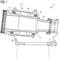
- Figure 1 shows a cross-section through part of a wind turbine drivetrain 2, showing a main bearing unit 9 in place about a low-speed shaft 10, and a coupling interface 20 at the downwind end of the shaft 10 for connection to the next stage of the drivetrain.
- the main bearing unit 9 is in place about the low-speed shaft 10 and comprises two tapered roller bearings 12, enclosed in a bearing housing 18.
- the housing 18 is secured to a bedplate 2B with a flat base for mounting to the top of a wind turbine tower (indicated by ghost lines).
- Each bearing 12 comprises tapered rollers arranged between an inner race and an outer race.
- Various annular elements are provided about the main shaft 10 and the housing 18 for applying preload to the bearings.
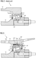
- Figure 2 shows a prior art rear bearing 12 of a main bearing unit 9, showing elements relevant to preloading the rear bearing 12.
- the position of the inner race 122 on the shaft is fixed by an annular component about the main shaft 10, e.g. a lock nut 10N.
- bearing preload can be achieved by stretching the shaft 10, for example with a hydraulic tool, while fixing the position of the rear bearing 12 relative to the housing 18, in a procedure that will be known to the skilled person.
- a press-fit between the rear bearing inner race 122 and the shaft 10 is relieved, for example by forcing pressurized fluid through passages 10F to form a fluid "cushion" between the contact surfaces of the inner race 122 and shaft 10.
- a suitable configuration of ducts or passages 10F are provided in the body of the shaft 10.
- the main bearing unit 9 can now be transported to a wind turbine for installation inside a nacelle.
- the bearing preload force F preload established during manufacture of the main bearing unit 9 may be sustained during the service life of a prior art wind turbine.
- the extended service life possible with present-day wind turbines means that the initial preload force is insufficient, but increasing the preload force at the outset can, as explained in the introduction, lead to bearing fatigue damage resulting in a premature defect or complete failure of the bearing.
- such an main bearing unit 9 would require an adjustable locking means such as an arrangement of fasteners between the shaft 10 and the inner race 122 of the rear bearing 12. Any such arrangement of fasteners must be accessible to a technician during the preloading procedure, and the necessary redesign of the main bearing unit 9 would add significantly to the overall cost.
- the inventive main bearing unit 1 has a structure is similar to the prior art main bearing unit 9 shown in Figure 1 .
- Bearing preload of the front and/or rear bearing can be set in the manufacturing facility using the inventive method, i.e. the same straightforward procedure is used to set the initial bearing preload and to reinstate bearing preload at any stage during the service life of the wind turbine, as will be explained in the following:
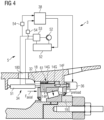
- FIGS 3 and Figure 4 show the rear bearing 12 in an exemplary embodiment of the inventive main bearing unit 1 (the following description may be assumed to apply equally to the front bearing).
- the bearing rollers 120 of the rear bearing 12 are inclined at an angle between the inner and outer races, and the bearing rollers of the front bearing may be assumed to be in inclined in the opposite direction, in what is commonly referred to as an "O" configuration.
- O the bearing rollers of the front bearing
- the reverse "X" configuration could equally be chosen, as the skilled person will be aware.
- a preload ring 14 is placed between the outer race 121 of the bearing 12 and the housing 18.
- an annular arrangement of preload fasteners 14F tension screws in this case
- Each preload fastener 14F passes through an axial bore 182 formed in the preload ring seat and is screwed into an axial threaded bore 142 formed in the preload ring 14.
- the preload force F preload acting on the outer race 121 of the rear bearing 12 can be the result of the press-fit between the preload ring 14 and the housing 18 and/or the result of tightening the preload fasteners 14F.
- the preload ring 14 is provided with an arrangement of ducts 14P extending between its "upwind" side face and its outward facing surface. These passages 14P can be used to establish a fluid cushion - an air cushion or fluid film - for preload setting during drivetrain assembly as well as during a bearing preload reinstatement procedure.
- the axial displacement means is a hydraulic cylinder 51 of a hydraulic arrangement 5, arranged inside the main bearing unit 1.
- the purpose of the hydraulic cylinder 51 is to apply an axial force F axial against the annular side face of the preload ring 14.
- radial pressure F pfit causing the press-fit between housing 18 and preload ring 14 is first relieved.
- the inventive bearing preloading arrangement 3 deploys a radial force relief means 32, which in this case is also part of the hydraulic arrangement 5, with hydraulic lines arranged to force pressurized fluid through preload ring passages 14P, creating a fluid cushion between housing 18 and preload ring 14, about the entire circumference of the preload ring 14, to facilitate axial displacement of the latter by the hydraulic cylinder 340, as indicated by the arrow.
- the preload ring position fixing means - in this case threaded fastener(s) 14F - can then be tightened using the tightening/tensioning tool 36 to a suitable torque or tensioning force.
- the preload fasteners 14F and the tightening/tensioning tool 36 can be deployed together as an axial displacement means. Once the fluid cushion is established between preload ring 14 and housing 18, the tool 36 can be actuated to turn or apply traction to the relevant preload fastener(s) 14F, thereby effecting the desired axial displacement of the preload ring 14. Equally, axial displacement can be effected by a hydraulic cylinder 51 as described above, in conjunction with the preload fasteners 14F and tensioning tool 36.
- the reinstated preload force F preload acting on the outer race 121 of the rear bearing 12 can be the result of the press-fit between the preload ring 14 and the housing 18 and/or the result of re-tightening the preload fasteners 14F.
- the hydraulic arrangement 5 further comprises a power unit 50 with tank, a pump 52, a control valve arrangement 53, pressure and/or flow sensors 54, and a suitable arrangement of fluid lines.
- a control module 38 can be used to control components of the hydraulic arrangement 5 to establish the hydraulic cushion between preload ring 14 and housing 18, to displace the preload ring 14, and to tighten the preload ring fixing means 14F.
- control module 38 controls hydraulic flow and/or pressure and the sequence of actuation of the pressure relief means 32 and the axial displacement means 34.
- the pressure relief means 32 can be controlled by measuring the hydraulic pressure/flow exerted by the pressure relief means 32, using a suitable sensor 54.
- An axial displacement of the preload ring 14 and the resulting bearing preload F preload can be monitored by measuring the hydraulic pressure/flow exerted by the axial displacement means 34 using a suitable sensor 54.
- the axial displacement between a bearing 12 and the housing 18 can also be measured using a suitable sensor.
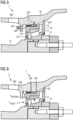
- Figure 5 and Figure 6 show the rear bearing 12 in a further exemplary embodiment of the inventive main bearing unit 1.
- the housing 18 of the main bearing unit 1 is constructed with an inwardly projecting flange to receive the preload fasteners 14F (thrust screws in this case), which are arranged to apply an axial force against the upwind face of the preload ring 14 as shown in Figure 4 .
- the preload ring 14 is provided with an arrangement of passages 14P as explained in Figure 3 .
- Each passage 14P opens into an annular or helical groove 14G extending about the circumference of the preload ring 14.
- An arrangement of parallel annular grooves 14G might be linked by a suitable arrangement of axial grooves.
- a more compact axial displacement means 34 is used, placed in a space between preload fasteners 14F as indicated in Figure 5 .
- the axial displacement means 34 is actuated to apply an axial force F axial against the annular side face of the preload ring 14, while pressurized fluid is forced into the ducts 14P of the preload ring 14 to relieve the press-fit between housing 18 and preload ring 14.
- the diagram also shows passages 18P formed in the housing 18, which could be used together with, or as an alternative to, the passages 14P formed in the preload ring 14 to establish the fluid cushion.
- the preload fasteners 14F are re-tightened. Each fastener 14F is tightened by an appropriate torque.
- the reinstated preload force F preload acting on the outer race 121 of the rear bearing 12 can be the result of the press-fit between the preload ring 14 and the housing 18 and/or the result of re-tightening the preload fasteners 14F.
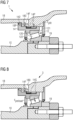
- Figure 7 and Figure 8 show the rear bearing 12 in a further exemplary embodiment of the inventive main bearing unit 1.
- the housing 18 of the main bearing unit 1 is constructed with an inwardly extending portion in which an annular arrangement of recesses 184 is provided to receive the preload fasteners 14F (tension screws in this case).
- the preload ring 14 comprises a flange 144 at its upwind end to lie against the inwardly extending portion of the housing 18.
- the preload fasteners 14F exert an axial traction force against the preload ring flange 144 as shown in Figure 7 .
- the preload ring 14 is provided with an arrangement of ducts 14P as explained above.
- an axial displacement tool or linear actuator such as a hydraulic cylinder is placed to exert an axial force against the preload ring 14 in a procedure similar to the procedure explained above, while a further hydraulic arrangement 32 forces pressurized fluid into the ducts 14P of the preload ring 14 to relieve the press-fit between housing 18 and preload ring 14.
- the reinstated preload force F preload acting on the outer race 121 of the rear bearing 12 can be the result of the press-fit between the preload ring 14 and the housing 18 and/or the result of re-tightening the preload fasteners 14F using a tool 36 as indicated in Figure 8 .
- Figure 9 and Figure 10 illustrates the inventive approach to reinstating the bearing preload in a main bearing unit as described in Figures 3 - 8 .
- the bearing preload of the rear bearing is monitored. For example, from a measured shaft elongation ⁇ L, the reduction in bearing preload force (from its initial value) can be computed.
- Figure 8 schematically indicates the initial bearing preload force F preload and the reduced bearing preload force F low (as indicated by the shorter arrow).
- FIG 11 shows an alternative embodiment of the invention.
- a preload ring 14 is located between the housing 18 and the front bearing 12 of the wind turbine drivetrain.
- the preloading fasteners 14F can be located on the upwind side of the front bearing 12, "pulling" the preload ring 14 towards the drive end of the shaft 10, thus stretching the shaft 10 relative to the housing 18, to reinstate preload force on the bearing 12.
- channels in the preload ring 14 allow a hydraulic tool to relieve the press-fit between the preload ring and the housing 18.
- the rear bearing can be equipped with its own preload ring and preloading fasteners as described above, i.e. both front and rear bearings 12 can be preloaded using the inventive approach.
- both front and rear bearings 12 can be preloaded using the inventive approach.
- only one of the two bearings is configured for preload reinstatement according to the invention, and the outer race of the other bearing can be secured to the bearing housing.
- Figure 12 shows an embodiment with an alternative preload ring fastening means 14N in the form of a large diameter locking nut 14N arranged between the preload ring 14 and the housing 18, with an outer thread to engage with a corresponding thread formed on the inner surface of the housing 18.
- a rotation lock may be provided, for example a form-fit pin (not shown), fixed to the housing and arranged to protrude into an axial bore formed in the preload ring. Such a pin prevents rotation of the preload ring while allowing it to be displaced in the axial direction during the preload setting procedure.
- This diagram also shows an alternative arrangement of passages 14P and grooves 18G.
- passages 14P in the preload ring 14 open into annular grooves 18G formed in the housing 18, for use in establishing the fluid cushion as described above.
- shim rings 19 may be arranged between the inner race of a bearing and a flange of the drivetrain, as will be known to the skilled person.
- fluid passages through the preload ring can open into annular grooves formed in the inside surface of the housing, or vice versa.
Landscapes
- Engineering & Computer Science (AREA)
- General Engineering & Computer Science (AREA)
- Mechanical Engineering (AREA)
- Life Sciences & Earth Sciences (AREA)
- Sustainable Development (AREA)
- Sustainable Energy (AREA)
- Chemical & Material Sciences (AREA)
- Combustion & Propulsion (AREA)
- Support Of The Bearing (AREA)
Priority Applications (2)
| Application Number | Priority Date | Filing Date | Title |
|---|---|---|---|
| EP23189135.9A EP4502372A1 (de) | 2023-08-02 | 2023-08-02 | Hauptlagereinheit |
| US18/787,205 US12480477B2 (en) | 2023-08-02 | 2024-07-29 | Main bearing unit |
Applications Claiming Priority (1)
| Application Number | Priority Date | Filing Date | Title |
|---|---|---|---|
| EP23189135.9A EP4502372A1 (de) | 2023-08-02 | 2023-08-02 | Hauptlagereinheit |
Publications (1)
| Publication Number | Publication Date |
|---|---|
| EP4502372A1 true EP4502372A1 (de) | 2025-02-05 |
Family
ID=87554705
Family Applications (1)
| Application Number | Title | Priority Date | Filing Date |
|---|---|---|---|
| EP23189135.9A Withdrawn EP4502372A1 (de) | 2023-08-02 | 2023-08-02 | Hauptlagereinheit |
Country Status (2)
| Country | Link |
|---|---|
| US (1) | US12480477B2 (de) |
| EP (1) | EP4502372A1 (de) |
Citations (3)
| Publication number | Priority date | Publication date | Assignee | Title |
|---|---|---|---|---|
| DE102009058355A1 (de) * | 2009-12-15 | 2011-06-16 | Aktiebolaget Skf | Wälzlagervorrichtung mit einer Ringkolbenhülse, Lageranordnung und Verfahren zum Einstellen der Anstellung einer hydraulisch anstellbaren Lageranordnung |
| WO2012097962A2 (de) * | 2011-01-17 | 2012-07-26 | Fm Energie Gmbh & Co.Kg | Hydraulisch vorspannbares wälzlager |
| US20170074317A1 (en) * | 2015-09-10 | 2017-03-16 | Aktiebolaget Skf | Tensioner and method for preloading a bearing |
Family Cites Families (5)
| Publication number | Priority date | Publication date | Assignee | Title |
|---|---|---|---|---|
| US3934957A (en) * | 1974-02-13 | 1976-01-27 | Fmc Corporation | Preloaded double row spherical roller bearing |
| US20030113049A1 (en) * | 2001-12-14 | 2003-06-19 | Morgan Construction Co | Laying head bearing with offset preloading |
| GB0511877D0 (en) * | 2005-06-10 | 2005-07-20 | Boc Group Plc | Vacuum pump |
| DE102010048546A1 (de) * | 2010-10-14 | 2012-04-19 | Schaeffler Technologies Gmbh & Co. Kg | Vorrichtung zur Einstellung der Vorspannung eines Schrägwälzlagers |
| EP3567267B1 (de) * | 2012-09-24 | 2021-06-16 | NTN Corporation | Lagervorrichtung mit einer kühlstruktur |
-
2023
- 2023-08-02 EP EP23189135.9A patent/EP4502372A1/de not_active Withdrawn
-
2024
- 2024-07-29 US US18/787,205 patent/US12480477B2/en active Active
Patent Citations (3)
| Publication number | Priority date | Publication date | Assignee | Title |
|---|---|---|---|---|
| DE102009058355A1 (de) * | 2009-12-15 | 2011-06-16 | Aktiebolaget Skf | Wälzlagervorrichtung mit einer Ringkolbenhülse, Lageranordnung und Verfahren zum Einstellen der Anstellung einer hydraulisch anstellbaren Lageranordnung |
| WO2012097962A2 (de) * | 2011-01-17 | 2012-07-26 | Fm Energie Gmbh & Co.Kg | Hydraulisch vorspannbares wälzlager |
| US20170074317A1 (en) * | 2015-09-10 | 2017-03-16 | Aktiebolaget Skf | Tensioner and method for preloading a bearing |
Also Published As
| Publication number | Publication date |
|---|---|
| US12480477B2 (en) | 2025-11-25 |
| US20250043774A1 (en) | 2025-02-06 |
Similar Documents
| Publication | Publication Date | Title |
|---|---|---|
| US9284949B2 (en) | Bearing arrangement of a wind turbine and method for adjusting the preload of a bearing arrangement | |
| US8858382B2 (en) | Pin retainer | |
| CN113107972B (zh) | 用于预紧轴承的张力装置和方法 | |
| KR20160134840A (ko) | 하이브리드 샤프트 베어링, 하이브리드 샤프트 베어링을 포함하는 풍력 발전기, 하이브리드 샤프트 베어링의 사용 및 하이브리드 샤프트 베어링 작동 방법 | |
| US20210285429A1 (en) | Hydrostatic machine comprising a cam ring | |
| CN121127686A (zh) | 流体动力或流体静力滑动轴承、用于设定流体动力或流体静力滑动轴承的轴承游隙的方法以及风力涡轮机 | |
| US20190085898A1 (en) | Bearing unit | |
| US9382941B2 (en) | Bearing retainer | |
| EP4502372A1 (de) | Hauptlagereinheit | |
| CA2721783A1 (en) | Preloaded propeller blade assembly | |
| CN101328859B (zh) | 风力发电机的主轴 | |
| EP3693579B1 (de) | Anlasserarretierungsanordnung und -verfahren | |
| EP4607050A1 (de) | Hauptlagereinheit | |
| CN213808477U (zh) | 一种风电主轴用大锥角双列圆锥滚子轴承 | |
| CN108291628B (zh) | 用于行星传动装置的传动级的行星架以及预紧方法 | |
| CN201225228Y (zh) | 风力发电机的主轴 | |
| CN120712406A (zh) | 用于降低和/或提升风力涡轮机的转子叶片的方法以及用于维修风力涡轮机的转子叶片的方法 | |
| EP3499031A1 (de) | Lageranordnung | |
| CN108044566B (zh) | 一种直升机旋翼轴主承力螺母装配方法 | |
| CN114922780B (zh) | 传动系组件 | |
| US20240410419A1 (en) | Bearing arrangement for a rotating component of a wind turbine | |
| EP4650614A1 (de) | Hauptlageranordnung mit einer vorspannungsanordnung und verfahren zum blockieren einer vorspannungskraft auf einem lager | |
| EP4675119A1 (de) | Geteilter klemmring | |
| EP4575251A1 (de) | Lageranordnung für ein rotierendes bauteil einer windenergieanlage | |
| CN113790218B (zh) | 一种液压可调胀紧连接套及装配方法 |
Legal Events
| Date | Code | Title | Description |
|---|---|---|---|
| PUAI | Public reference made under article 153(3) epc to a published international application that has entered the european phase |
Free format text: ORIGINAL CODE: 0009012 |
|
| STAA | Information on the status of an ep patent application or granted ep patent |
Free format text: STATUS: THE APPLICATION HAS BEEN PUBLISHED |
|
| AK | Designated contracting states |
Kind code of ref document: A1 Designated state(s): AL AT BE BG CH CY CZ DE DK EE ES FI FR GB GR HR HU IE IS IT LI LT LU LV MC ME MK MT NL NO PL PT RO RS SE SI SK SM TR |
|
| STAA | Information on the status of an ep patent application or granted ep patent |
Free format text: STATUS: REQUEST FOR EXAMINATION WAS MADE |
|
| 17P | Request for examination filed |
Effective date: 20250805 |
|
| STAA | Information on the status of an ep patent application or granted ep patent |
Free format text: STATUS: EXAMINATION IS IN PROGRESS |
|
| 17Q | First examination report despatched |
Effective date: 20251006 |
|
| STAA | Information on the status of an ep patent application or granted ep patent |
Free format text: STATUS: THE APPLICATION IS DEEMED TO BE WITHDRAWN |
|
| 18D | Application deemed to be withdrawn |
Effective date: 20251209 |