EP4502462A1 - Projecteur de faisceau lumineux - Google Patents
Projecteur de faisceau lumineux Download PDFInfo
- Publication number
- EP4502462A1 EP4502462A1 EP24191834.1A EP24191834A EP4502462A1 EP 4502462 A1 EP4502462 A1 EP 4502462A1 EP 24191834 A EP24191834 A EP 24191834A EP 4502462 A1 EP4502462 A1 EP 4502462A1
- Authority
- EP
- European Patent Office
- Prior art keywords
- projector
- flange
- light beam
- annular body
- edge
- Prior art date
- Legal status (The legal status is an assumption and is not a legal conclusion. Google has not performed a legal analysis and makes no representation as to the accuracy of the status listed.)
- Pending
Links
Images


Classifications
-
- F—MECHANICAL ENGINEERING; LIGHTING; HEATING; WEAPONS; BLASTING
- F21—LIGHTING
- F21V—FUNCTIONAL FEATURES OR DETAILS OF LIGHTING DEVICES OR SYSTEMS THEREOF; STRUCTURAL COMBINATIONS OF LIGHTING DEVICES WITH OTHER ARTICLES, NOT OTHERWISE PROVIDED FOR
- F21V5/00—Refractors for light sources
- F21V5/04—Refractors for light sources of lens shape
-
- F—MECHANICAL ENGINEERING; LIGHTING; HEATING; WEAPONS; BLASTING
- F21—LIGHTING
- F21S—NON-PORTABLE LIGHTING DEVICES; SYSTEMS THEREOF; VEHICLE LIGHTING DEVICES SPECIALLY ADAPTED FOR VEHICLE EXTERIORS
- F21S41/00—Illuminating devices specially adapted for vehicle exteriors, e.g. headlamps
- F21S41/20—Illuminating devices specially adapted for vehicle exteriors, e.g. headlamps characterised by refractors, transparent cover plates, light guides or filters
- F21S41/29—Attachment thereof
- F21S41/295—Attachment thereof specially adapted to projection lenses
-
- F—MECHANICAL ENGINEERING; LIGHTING; HEATING; WEAPONS; BLASTING
- F21—LIGHTING
- F21S—NON-PORTABLE LIGHTING DEVICES; SYSTEMS THEREOF; VEHICLE LIGHTING DEVICES SPECIALLY ADAPTED FOR VEHICLE EXTERIORS
- F21S41/00—Illuminating devices specially adapted for vehicle exteriors, e.g. headlamps
- F21S41/60—Illuminating devices specially adapted for vehicle exteriors, e.g. headlamps characterised by a variable light distribution
- F21S41/63—Illuminating devices specially adapted for vehicle exteriors, e.g. headlamps characterised by a variable light distribution by acting on refractors, filters or transparent cover plates
- F21S41/635—Illuminating devices specially adapted for vehicle exteriors, e.g. headlamps characterised by a variable light distribution by acting on refractors, filters or transparent cover plates by moving refractors, filters or transparent cover plates
-
- F—MECHANICAL ENGINEERING; LIGHTING; HEATING; WEAPONS; BLASTING
- F21—LIGHTING
- F21V—FUNCTIONAL FEATURES OR DETAILS OF LIGHTING DEVICES OR SYSTEMS THEREOF; STRUCTURAL COMBINATIONS OF LIGHTING DEVICES WITH OTHER ARTICLES, NOT OTHERWISE PROVIDED FOR
- F21V14/00—Controlling the distribution of the light emitted by adjustment of elements
- F21V14/06—Controlling the distribution of the light emitted by adjustment of elements by movement of refractors
-
- F—MECHANICAL ENGINEERING; LIGHTING; HEATING; WEAPONS; BLASTING
- F21—LIGHTING
- F21V—FUNCTIONAL FEATURES OR DETAILS OF LIGHTING DEVICES OR SYSTEMS THEREOF; STRUCTURAL COMBINATIONS OF LIGHTING DEVICES WITH OTHER ARTICLES, NOT OTHERWISE PROVIDED FOR
- F21V17/00—Fastening of component parts of lighting devices, e.g. shades, globes, refractors, reflectors, filters, screens, grids or protective cages
- F21V17/02—Fastening of component parts of lighting devices, e.g. shades, globes, refractors, reflectors, filters, screens, grids or protective cages with provision for adjustment
-
- G—PHYSICS
- G02—OPTICS
- G02B—OPTICAL ELEMENTS, SYSTEMS OR APPARATUS
- G02B7/00—Mountings, adjusting means, or light-tight connections, for optical elements
- G02B7/02—Mountings, adjusting means, or light-tight connections, for optical elements for lenses
- G02B7/023—Mountings, adjusting means, or light-tight connections, for optical elements for lenses permitting adjustment
-
- F—MECHANICAL ENGINEERING; LIGHTING; HEATING; WEAPONS; BLASTING
- F21—LIGHTING
- F21S—NON-PORTABLE LIGHTING DEVICES; SYSTEMS THEREOF; VEHICLE LIGHTING DEVICES SPECIALLY ADAPTED FOR VEHICLE EXTERIORS
- F21S41/00—Illuminating devices specially adapted for vehicle exteriors, e.g. headlamps
- F21S41/40—Illuminating devices specially adapted for vehicle exteriors, e.g. headlamps characterised by screens, non-reflecting members, light-shielding members or fixed shades
- F21S41/47—Attachment thereof
-
- F—MECHANICAL ENGINEERING; LIGHTING; HEATING; WEAPONS; BLASTING
- F21—LIGHTING
- F21V—FUNCTIONAL FEATURES OR DETAILS OF LIGHTING DEVICES OR SYSTEMS THEREOF; STRUCTURAL COMBINATIONS OF LIGHTING DEVICES WITH OTHER ARTICLES, NOT OTHERWISE PROVIDED FOR
- F21V14/00—Controlling the distribution of the light emitted by adjustment of elements
- F21V14/06—Controlling the distribution of the light emitted by adjustment of elements by movement of refractors
- F21V14/065—Controlling the distribution of the light emitted by adjustment of elements by movement of refractors in portable lighting devices
-
- F—MECHANICAL ENGINEERING; LIGHTING; HEATING; WEAPONS; BLASTING
- F21—LIGHTING
- F21W—INDEXING SCHEME ASSOCIATED WITH SUBCLASSES F21K, F21L, F21S and F21V, RELATING TO USES OR APPLICATIONS OF LIGHTING DEVICES OR SYSTEMS
- F21W2131/00—Use or application of lighting devices or systems not provided for in codes F21W2102/00-F21W2121/00
- F21W2131/20—Lighting for medical use
- F21W2131/205—Lighting for medical use for operating theatres
-
- F—MECHANICAL ENGINEERING; LIGHTING; HEATING; WEAPONS; BLASTING
- F21—LIGHTING
- F21W—INDEXING SCHEME ASSOCIATED WITH SUBCLASSES F21K, F21L, F21S and F21V, RELATING TO USES OR APPLICATIONS OF LIGHTING DEVICES OR SYSTEMS
- F21W2131/00—Use or application of lighting devices or systems not provided for in codes F21W2102/00-F21W2121/00
- F21W2131/40—Lighting for industrial, commercial, recreational or military use
- F21W2131/406—Lighting for industrial, commercial, recreational or military use for theatres, stages or film studios
Definitions
- This invention relates to a projector of a light beam.
- One of the various types of projectors present on the market is those which are able to generate light beams directed for outdoor use.
- these projectors comprise a containment and support frame (or housing), having a main extension along the axis of emission of the light beam and containing inside it at least the following components: a controlled source for projection of a light beam (for example LED type sources) at a first end of the frame, and a single glass lens for the output of the light beam associated with the other end of the frame.
- a controlled source for projection of a light beam for example LED type sources
- a single glass lens for the output of the light beam associated with the other end of the frame.
- the projector body made in this way must obviously have a seal against external agents (sunlight, water, etc.).
- this type of the projector offers the possibility of modifying the opening beam of the projection using at least one additional lens positioned inside the frame and interposed between the light source and the end glass.
- the addition of a lens or the replacement of the one already mounted inside the frame comprises a relatively long and laborious assembly of the lenses, since it requires a variety of equipment and tools in order to be able to remove the front end glass, make a correct assembly of the lens(es) inside and refit the front glass.
- the additional lens provided with an annular supporting body (holder), may be mounted on the outer side of the frame of the projector at a certain distance of the front glass through an independent support applied, at the moment, on the frame where they remain fixed.
- This feature gives it a certain amount of space or distance between the front glass and the optional lens.
- This distance between optional lens and glass creates a problem in the optical system and is usually the cause of: a different angle of opening of the light beam from that desired, a loss of efficiency and possible unwanted escape of lateral light (“spill light").
- the optional or additional lenses are made of plastic material and, therefore, once installed outside the projector, they have accelerated deterioration if exposed to moist environments or if exposed to direct sunlight.
- the lenses therefore, have a rapid ageing which generates an irreversible transformation of the lens with a consequent loss of efficiency as well as a mechanical weakening with relative need for fast replacement and disposal of the old lens.
- the aim of this invention is to provide a projector of a light beam which overcomes the drawbacks of the prior art described above.
- the aim of this invention is to provide a projector of a light beam which can be accessorised quickly and precisely with additional lenses without the need for particular equipment.
- a further aim of the invention is to provide a projector of a light beam which is able to have a compact structure and with the possibility of rapid removal and/or replacement of the additional lens without the need for special equipment or tools.
- the projector of a light beam according to the invention may be, but without limiting the scope of the invention, used for lighting outdoor events.
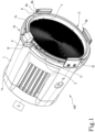
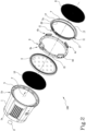
- the projector 100 comprises a projector body 1 (box-shaped body) having a first end and a second end to define a longitudinal axis of extension.
- the projector 100 also comprises a light source 2 (for example, a LED unit indicated with a block in Figures 1 and 2 ), positioned inside the projector body 1 close to the first end and configured for emitting a light beam along a direction F of emission and in a sense of emission extending from the first end to the second end of the projector body 1.
- a light source 2 for example, a LED unit indicated with a block in Figures 1 and 2
- the projector 100 also comprises a front covering glass 3 for the outlet of the light beam positioned at the second end 1b of the projector body 1.
- the projector 100 comprises a plurality of flanges 4a-4d associated with the annular edge 5 of the second end 1b of the projector body 1. At least one of these flanges, labelled 4a, is movable.
- Each flange 4a-4d protrudes parallel to the direction F of emission of the light beam.
- Each flange 4a-4d is also equipped with at least one curved channel 6 formed on its inner surface.
- the flanges 4a-4b are associated with a rigid ring 21 which can be coupled with the annular edge 5 of the projector body 1.
- the projector 100 also comprises an annular body 7 for housing a first lens 8 configured for modifying the projection of the light beam.
- the annular body 7 has an edge 7a configured for housing, in use, inside the relative channel 6 present on each flange 4a-4d.
- the projector 100 also comprises means 9 for quick, reversible locking of the annular body 7 on the flanges 4a-4d positioned on at least the movable flange 4a and configured for stably positioning the first lens 7 close to the front glass 3 in a position centred relative to the direction F of the light beam.
- the projector 100 has the possibility of adding and removing an additional lens outside the projector in a fast and simple manner and with the certainty of correct centring of the lens relative to the direction of the light beam.
- the projector 100 may comprise a second lens 10 configured for modifying the projection of the light beam housed inside the projector body 1, between the light source 2 and the front glass 3 and positioned in a position centred relative to the direction F of the light beam.
- the edge 7a of the annular body 7 is equipped with means 11 for relative positioning with the flanges 4a-4d and configured for forming a constrained space for at least the movable flange labelled 4a, by a rotation of the annular body 7 after a free positioning, towards the front glass 3, of the annular edge 7a to the channel 6 of each flange 4a-4d (as described below).
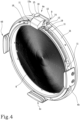
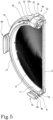
- the quick, reversible locking means 9 comprise a box-shaped support 12 associated with the frame 1 of the projector and having a pin 13 partly housed inside the support 12 on which is articulated the movable flange 4a in such a way as to rotate between:
- the quick, reversible locking means 9 comprise an elastic element 14 (helical spring) fitted on the pin 13, retained between an inner wall of the support 12 and a (lateral) surface of the movable flange 4a, and configured to allow the movable flange 4a to be kept in the first lowered operating position or in the second raised operating position.
- an elastic element 14 helical spring
- a control element 13a (pushbutton), outside the box-shaped support 12 and acting on the pin 13 to allow the translation of the pin 13 and the movable flange 4a along the box-shaped support 12, with relative compression of the elastic element 14, in such a way as to move the movable flange 4a from the first lowered operating position to the second raised operating position and vice versa (see Figures 3 and 4 ).
- these comprises a plurality of recesses 17 made on the edge 7a of the annular body 7 to allow the free passage towards the front glass 3 of the annular body 7 through the respective flanges 4b-4d positioned on the frame 1.
- the positioning means 11 also comprise a pair of enlargements 18 and 19 made on a front surface of the edge 7a of the annular body 7 and positioned at a distance from each other in such a way as to form a limited space on the stable engagement edge 7a for the movable flange 4a following rotation of the annular body 7.
- the enlargements 18 and 19 are configured to define a precise angle of rotation so as to move the relative recesses 17 of the edge 7a away from the channel 6 of each remaining flange 4b-4d and in such a way as to couple the edge 7a to the relative channel 6 of each remaining flange 4b-4d.
- the pair of enlargements 18 and 19, in use being configured to prevent a counter-rotation of releasing of the annular body 7 due to a bilateral locking on the movable flange 4a in the lowered configuration.
- the movable flange 4a can therefore be moved from the lowered position to the raised position by a pushing action from the outside of the button 13a which allows the pin 13 and the flange 4a associated with it to translate in a first direction in such a way as to move the flange 4a away from the bracket 15 and therefore be able to lift the flange 4a.
- the spring 14 tends to compress the flange 4a, in a direction opposite to the first direction, against the bracket 14, stabilising it in the raised position.
- the annular body 7 can be inserted through the fixed flanges 4b, 4c and 4d, thanks to the recesses 17 which allow it to pass freely until making contact with the channel 6 of the fixed flanges 4b, 4c, 4d.
- the annular body 7a can no longer be rotated and is stably fixed to the projector 100.
- At least three curved channels 6, 6a, 6b are made one after the other on each flange 4a-4d.
- Additional channels 6a, 6b may be used to apply any further optical accessories superposed on the first lens, if necessary.
- annular body 7 is made of flexible material and comprises the edge 7a having a fork-shaped cross-section configured to allow a sliding locking by interference inside the channel 6 of each flange 4a-4d (see also Figure 6 ).
- the annular body 7 also has an annular sleeve 20 for stably housing the first lens 8.
- the sleeve 20 is recessed relative to the edge 7a in such a way as to position, in use, the first lens 8 closer to the front glass 3 than the position of the edge 7a coupled to the flanges 4a-4d.
- the first lens 8 is fitted according to the following steps:
- the preset aims are achieved and with significant advantages.
- the lens is mounted quickly, precisely and without the need for tools.
- the annular supporting body of the first lens is structured with a geometry configured to have the first lens in a recessed position relative to the anchoring point of the annular body on the frame of the projector.
- the lens can "adhere" perfectly relative to the point of emission of the light, thus allowing the desired angle of opening to be obtained without loss of efficiency and avoiding the "spill light” phenomena.
- the first outer lens may be extracted easily and without tools from its annular body made of rubber and also housed inside the projector, behind the front glass, avoiding its deterioration and preserving the integrity of the lens.
Landscapes
- Engineering & Computer Science (AREA)
- General Engineering & Computer Science (AREA)
- Physics & Mathematics (AREA)
- General Physics & Mathematics (AREA)
- Optics & Photonics (AREA)
- Non-Portable Lighting Devices Or Systems Thereof (AREA)
Applications Claiming Priority (1)
| Application Number | Priority Date | Filing Date | Title |
|---|---|---|---|
| IT202300016590 | 2023-08-03 |
Publications (1)
| Publication Number | Publication Date |
|---|---|
| EP4502462A1 true EP4502462A1 (fr) | 2025-02-05 |
Family
ID=88413461
Family Applications (1)
| Application Number | Title | Priority Date | Filing Date |
|---|---|---|---|
| EP24191834.1A Pending EP4502462A1 (fr) | 2023-08-03 | 2024-07-30 | Projecteur de faisceau lumineux |
Country Status (1)
| Country | Link |
|---|---|
| EP (1) | EP4502462A1 (fr) |
Citations (7)
| Publication number | Priority date | Publication date | Assignee | Title |
|---|---|---|---|---|
| CN1432117A (zh) * | 2000-05-03 | 2003-07-23 | N.V.Adbttv科技股份有限公司 | 照明器材 |
| US20040042085A1 (en) * | 2002-08-28 | 2004-03-04 | Hough Thomas A. | Zoomable beamspreader for non-imaging illumination applications |
| US20100033977A1 (en) * | 2006-10-12 | 2010-02-11 | Arnold & Richter Cine Technik Gmbh & Co. Betriebs | Spotlight for illumination in film, studio, event or theatre environments |
| WO2011127481A2 (fr) * | 2010-04-09 | 2011-10-13 | Litepanels, Ltd. | Système d'éclairage à lentille de fresnel muni de led, monté sur une caméra et comprenant un système de refroidissement actif |
| WO2014079132A1 (fr) * | 2012-11-23 | 2014-05-30 | 广州市雅江光电设备有限公司 | Système de rayonnement et procédé de rayonnement d'une lampe à del filetée à faisceau étroit |
| US20160178153A1 (en) * | 2013-08-13 | 2016-06-23 | Hella Kgaa Hueck & Co. | Projection module for a headlight of a vehicle |
| CN211344820U (zh) * | 2020-02-20 | 2020-08-25 | 深圳市爱图仕影像器材有限公司 | 一种摄影灯 |
-
2024
- 2024-07-30 EP EP24191834.1A patent/EP4502462A1/fr active Pending
Patent Citations (7)
| Publication number | Priority date | Publication date | Assignee | Title |
|---|---|---|---|---|
| CN1432117A (zh) * | 2000-05-03 | 2003-07-23 | N.V.Adbttv科技股份有限公司 | 照明器材 |
| US20040042085A1 (en) * | 2002-08-28 | 2004-03-04 | Hough Thomas A. | Zoomable beamspreader for non-imaging illumination applications |
| US20100033977A1 (en) * | 2006-10-12 | 2010-02-11 | Arnold & Richter Cine Technik Gmbh & Co. Betriebs | Spotlight for illumination in film, studio, event or theatre environments |
| WO2011127481A2 (fr) * | 2010-04-09 | 2011-10-13 | Litepanels, Ltd. | Système d'éclairage à lentille de fresnel muni de led, monté sur une caméra et comprenant un système de refroidissement actif |
| WO2014079132A1 (fr) * | 2012-11-23 | 2014-05-30 | 广州市雅江光电设备有限公司 | Système de rayonnement et procédé de rayonnement d'une lampe à del filetée à faisceau étroit |
| US20160178153A1 (en) * | 2013-08-13 | 2016-06-23 | Hella Kgaa Hueck & Co. | Projection module for a headlight of a vehicle |
| CN211344820U (zh) * | 2020-02-20 | 2020-08-25 | 深圳市爱图仕影像器材有限公司 | 一种摄影灯 |
Similar Documents
| Publication | Publication Date | Title |
|---|---|---|
| US7572034B2 (en) | Multiple side illumination assembly | |
| ATE340965T1 (de) | Operationsleucthtensteuerung | |
| WO2017031024A1 (fr) | Capot d'extrémité pour appareil d'éclairage | |
| EP1384941A3 (fr) | Projecteur avec faisceau lumineux à limitation périphérique | |
| ES2184824T3 (es) | Lampara medica con unidad de proyeccion compuesta. | |
| JP2012502423A (ja) | ランプアセンブリ | |
| EP3428520A1 (fr) | Opération externe de luminaire étanche utilisant une force magnétique | |
| CA3257702A1 (fr) | Ensemble lentille pour un dispositif d'éclairage | |
| ES2191414T3 (es) | Dispositivo de iluminacion para campo operatorio, del tipo que no proyecta sombra. | |
| IT1308865B1 (it) | Sistema ottico di illuminamento per videoproiettore. | |
| DK1021677T3 (da) | Projektør med lineær reflektor | |
| JP4419059B2 (ja) | 天井埋込形照明器具 | |
| DK0522480T3 (da) | Elektrisk belysningsarmatur med afblændingsskærm og metode til at fremstille en sådan afblændingsskærm | |
| JPH0620513A (ja) | 照明器具 | |
| US2169531A (en) | Headlight construction | |
| ATE135473T1 (de) | Beleuchtungseinrichtung für optische geräte mit separaten beleuchtungsstrahlengängen | |
| KR20180001528U (ko) | 조명등의 투광판 고정구 장착장치 | |
| DK168898B1 (da) | Belysningsindretning i et projektionskopieringsapparat | |
| ES2140810T3 (es) | Procedimiento de fabricacion de un tubo cilindrico de carton kraft, medios para la realizacion de dicho procedimiento y tubos cilindricos asi obtenidos. | |
| EP4468050B1 (fr) | Une unité d'une lentille pour un effet optique | |
| EP4542110B1 (fr) | Projecteur de faisceaux lumineux | |
| NO163982B (no) | Eksplosjonsbeskyttet lampe. | |
| JPS5937522B2 (ja) | 照明器具 | |
| KR101747024B1 (ko) | 조명등의 투광판홀더 체결장치 | |
| US20050231952A1 (en) | Direct-indirect luminaire with shutter |
Legal Events
| Date | Code | Title | Description |
|---|---|---|---|
| PUAI | Public reference made under article 153(3) epc to a published international application that has entered the european phase |
Free format text: ORIGINAL CODE: 0009012 |
|
| STAA | Information on the status of an ep patent application or granted ep patent |
Free format text: STATUS: THE APPLICATION HAS BEEN PUBLISHED |
|
| AK | Designated contracting states |
Kind code of ref document: A1 Designated state(s): AL AT BE BG CH CY CZ DE DK EE ES FI FR GB GR HR HU IE IS IT LI LT LU LV MC ME MK MT NL NO PL PT RO RS SE SI SK SM TR |
|
| STAA | Information on the status of an ep patent application or granted ep patent |
Free format text: STATUS: REQUEST FOR EXAMINATION WAS MADE |
|
| 17P | Request for examination filed |
Effective date: 20250626 |