EP4502479A1 - Climatiseur et dispositif électrique de collecte de poussière - Google Patents
Climatiseur et dispositif électrique de collecte de poussière Download PDFInfo
- Publication number
- EP4502479A1 EP4502479A1 EP23863356.4A EP23863356A EP4502479A1 EP 4502479 A1 EP4502479 A1 EP 4502479A1 EP 23863356 A EP23863356 A EP 23863356A EP 4502479 A1 EP4502479 A1 EP 4502479A1
- Authority
- EP
- European Patent Office
- Prior art keywords
- electrode
- upstream
- discharge electrode
- disposed
- discharge
- Prior art date
- Legal status (The legal status is an assumption and is not a legal conclusion. Google has not performed a legal analysis and makes no representation as to the accuracy of the status listed.)
- Pending
Links
Images




Classifications
-
- F—MECHANICAL ENGINEERING; LIGHTING; HEATING; WEAPONS; BLASTING
- F24—HEATING; RANGES; VENTILATING
- F24F—AIR-CONDITIONING; AIR-HUMIDIFICATION; VENTILATION; USE OF AIR CURRENTS FOR SCREENING
- F24F8/00—Treatment, e.g. purification, of air supplied to human living or working spaces otherwise than by heating, cooling, humidifying or drying
- F24F8/10—Treatment, e.g. purification, of air supplied to human living or working spaces otherwise than by heating, cooling, humidifying or drying by separation, e.g. by filtering
- F24F8/192—Treatment, e.g. purification, of air supplied to human living or working spaces otherwise than by heating, cooling, humidifying or drying by separation, e.g. by filtering by electrical means, e.g. by applying electrostatic fields or high voltages
- F24F8/194—Treatment, e.g. purification, of air supplied to human living or working spaces otherwise than by heating, cooling, humidifying or drying by separation, e.g. by filtering by electrical means, e.g. by applying electrostatic fields or high voltages by filtering using high voltage
-
- F—MECHANICAL ENGINEERING; LIGHTING; HEATING; WEAPONS; BLASTING
- F24—HEATING; RANGES; VENTILATING
- F24F—AIR-CONDITIONING; AIR-HUMIDIFICATION; VENTILATION; USE OF AIR CURRENTS FOR SCREENING
- F24F8/00—Treatment, e.g. purification, of air supplied to human living or working spaces otherwise than by heating, cooling, humidifying or drying
- F24F8/10—Treatment, e.g. purification, of air supplied to human living or working spaces otherwise than by heating, cooling, humidifying or drying by separation, e.g. by filtering
- F24F8/192—Treatment, e.g. purification, of air supplied to human living or working spaces otherwise than by heating, cooling, humidifying or drying by separation, e.g. by filtering by electrical means, e.g. by applying electrostatic fields or high voltages
-
- B—PERFORMING OPERATIONS; TRANSPORTING
- B03—SEPARATION OF SOLID MATERIALS USING LIQUIDS OR USING PNEUMATIC TABLES OR JIGS; MAGNETIC OR ELECTROSTATIC SEPARATION OF SOLID MATERIALS FROM SOLID MATERIALS OR FLUIDS; SEPARATION BY HIGH-VOLTAGE ELECTRIC FIELDS
- B03C—MAGNETIC OR ELECTROSTATIC SEPARATION OF SOLID MATERIALS FROM SOLID MATERIALS OR FLUIDS; SEPARATION BY HIGH-VOLTAGE ELECTRIC FIELDS
- B03C3/00—Separating dispersed particles from gases or vapour, e.g. air, by electrostatic effect
- B03C3/02—Plant or installations having external electricity supply
- B03C3/04—Plant or installations having external electricity supply dry type
- B03C3/09—Plant or installations having external electricity supply dry type characterised by presence of stationary flat electrodes arranged with their flat surfaces at right angles to the gas stream
-
- B—PERFORMING OPERATIONS; TRANSPORTING
- B03—SEPARATION OF SOLID MATERIALS USING LIQUIDS OR USING PNEUMATIC TABLES OR JIGS; MAGNETIC OR ELECTROSTATIC SEPARATION OF SOLID MATERIALS FROM SOLID MATERIALS OR FLUIDS; SEPARATION BY HIGH-VOLTAGE ELECTRIC FIELDS
- B03C—MAGNETIC OR ELECTROSTATIC SEPARATION OF SOLID MATERIALS FROM SOLID MATERIALS OR FLUIDS; SEPARATION BY HIGH-VOLTAGE ELECTRIC FIELDS
- B03C3/00—Separating dispersed particles from gases or vapour, e.g. air, by electrostatic effect
- B03C3/02—Plant or installations having external electricity supply
- B03C3/04—Plant or installations having external electricity supply dry type
- B03C3/12—Plant or installations having external electricity supply dry type characterised by separation of ionising and collecting stations
-
- B—PERFORMING OPERATIONS; TRANSPORTING
- B03—SEPARATION OF SOLID MATERIALS USING LIQUIDS OR USING PNEUMATIC TABLES OR JIGS; MAGNETIC OR ELECTROSTATIC SEPARATION OF SOLID MATERIALS FROM SOLID MATERIALS OR FLUIDS; SEPARATION BY HIGH-VOLTAGE ELECTRIC FIELDS
- B03C—MAGNETIC OR ELECTROSTATIC SEPARATION OF SOLID MATERIALS FROM SOLID MATERIALS OR FLUIDS; SEPARATION BY HIGH-VOLTAGE ELECTRIC FIELDS
- B03C3/00—Separating dispersed particles from gases or vapour, e.g. air, by electrostatic effect
- B03C3/32—Transportable units, e.g. for cleaning room air
-
- B—PERFORMING OPERATIONS; TRANSPORTING
- B03—SEPARATION OF SOLID MATERIALS USING LIQUIDS OR USING PNEUMATIC TABLES OR JIGS; MAGNETIC OR ELECTROSTATIC SEPARATION OF SOLID MATERIALS FROM SOLID MATERIALS OR FLUIDS; SEPARATION BY HIGH-VOLTAGE ELECTRIC FIELDS
- B03C—MAGNETIC OR ELECTROSTATIC SEPARATION OF SOLID MATERIALS FROM SOLID MATERIALS OR FLUIDS; SEPARATION BY HIGH-VOLTAGE ELECTRIC FIELDS
- B03C3/00—Separating dispersed particles from gases or vapour, e.g. air, by electrostatic effect
- B03C3/34—Constructional details or accessories or operation thereof
- B03C3/36—Controlling flow of gases or vapour
-
- B—PERFORMING OPERATIONS; TRANSPORTING
- B03—SEPARATION OF SOLID MATERIALS USING LIQUIDS OR USING PNEUMATIC TABLES OR JIGS; MAGNETIC OR ELECTROSTATIC SEPARATION OF SOLID MATERIALS FROM SOLID MATERIALS OR FLUIDS; SEPARATION BY HIGH-VOLTAGE ELECTRIC FIELDS
- B03C—MAGNETIC OR ELECTROSTATIC SEPARATION OF SOLID MATERIALS FROM SOLID MATERIALS OR FLUIDS; SEPARATION BY HIGH-VOLTAGE ELECTRIC FIELDS
- B03C3/00—Separating dispersed particles from gases or vapour, e.g. air, by electrostatic effect
- B03C3/34—Constructional details or accessories or operation thereof
- B03C3/36—Controlling flow of gases or vapour
- B03C3/368—Controlling flow of gases or vapour by other than static mechanical means, e.g. internal ventilator or recycler
-
- B—PERFORMING OPERATIONS; TRANSPORTING
- B03—SEPARATION OF SOLID MATERIALS USING LIQUIDS OR USING PNEUMATIC TABLES OR JIGS; MAGNETIC OR ELECTROSTATIC SEPARATION OF SOLID MATERIALS FROM SOLID MATERIALS OR FLUIDS; SEPARATION BY HIGH-VOLTAGE ELECTRIC FIELDS
- B03C—MAGNETIC OR ELECTROSTATIC SEPARATION OF SOLID MATERIALS FROM SOLID MATERIALS OR FLUIDS; SEPARATION BY HIGH-VOLTAGE ELECTRIC FIELDS
- B03C3/00—Separating dispersed particles from gases or vapour, e.g. air, by electrostatic effect
- B03C3/34—Constructional details or accessories or operation thereof
- B03C3/38—Particle charging or ionising stations, e.g. using electric discharge, radioactive radiation or flames
-
- B—PERFORMING OPERATIONS; TRANSPORTING
- B03—SEPARATION OF SOLID MATERIALS USING LIQUIDS OR USING PNEUMATIC TABLES OR JIGS; MAGNETIC OR ELECTROSTATIC SEPARATION OF SOLID MATERIALS FROM SOLID MATERIALS OR FLUIDS; SEPARATION BY HIGH-VOLTAGE ELECTRIC FIELDS
- B03C—MAGNETIC OR ELECTROSTATIC SEPARATION OF SOLID MATERIALS FROM SOLID MATERIALS OR FLUIDS; SEPARATION BY HIGH-VOLTAGE ELECTRIC FIELDS
- B03C3/00—Separating dispersed particles from gases or vapour, e.g. air, by electrostatic effect
- B03C3/34—Constructional details or accessories or operation thereof
- B03C3/40—Electrode constructions
- B03C3/41—Ionising-electrodes
-
- B—PERFORMING OPERATIONS; TRANSPORTING
- B03—SEPARATION OF SOLID MATERIALS USING LIQUIDS OR USING PNEUMATIC TABLES OR JIGS; MAGNETIC OR ELECTROSTATIC SEPARATION OF SOLID MATERIALS FROM SOLID MATERIALS OR FLUIDS; SEPARATION BY HIGH-VOLTAGE ELECTRIC FIELDS
- B03C—MAGNETIC OR ELECTROSTATIC SEPARATION OF SOLID MATERIALS FROM SOLID MATERIALS OR FLUIDS; SEPARATION BY HIGH-VOLTAGE ELECTRIC FIELDS
- B03C3/00—Separating dispersed particles from gases or vapour, e.g. air, by electrostatic effect
- B03C3/34—Constructional details or accessories or operation thereof
- B03C3/40—Electrode constructions
- B03C3/45—Collecting-electrodes
-
- B—PERFORMING OPERATIONS; TRANSPORTING
- B03—SEPARATION OF SOLID MATERIALS USING LIQUIDS OR USING PNEUMATIC TABLES OR JIGS; MAGNETIC OR ELECTROSTATIC SEPARATION OF SOLID MATERIALS FROM SOLID MATERIALS OR FLUIDS; SEPARATION BY HIGH-VOLTAGE ELECTRIC FIELDS
- B03C—MAGNETIC OR ELECTROSTATIC SEPARATION OF SOLID MATERIALS FROM SOLID MATERIALS OR FLUIDS; SEPARATION BY HIGH-VOLTAGE ELECTRIC FIELDS
- B03C3/00—Separating dispersed particles from gases or vapour, e.g. air, by electrostatic effect
- B03C3/34—Constructional details or accessories or operation thereof
- B03C3/40—Electrode constructions
- B03C3/45—Collecting-electrodes
- B03C3/47—Collecting-electrodes flat, e.g. plates, discs, gratings
-
- F—MECHANICAL ENGINEERING; LIGHTING; HEATING; WEAPONS; BLASTING
- F24—HEATING; RANGES; VENTILATING
- F24F—AIR-CONDITIONING; AIR-HUMIDIFICATION; VENTILATION; USE OF AIR CURRENTS FOR SCREENING
- F24F1/00—Room units for air-conditioning, e.g. separate or self-contained units or units receiving primary air from a central station
- F24F1/02—Self-contained room units for air-conditioning, i.e. with all apparatus for treatment installed in a common casing
- F24F1/0328—Self-contained room units for air-conditioning, i.e. with all apparatus for treatment installed in a common casing with means for purifying supplied air
- F24F1/0353—Self-contained room units for air-conditioning, i.e. with all apparatus for treatment installed in a common casing with means for purifying supplied air by electric means, e.g. ionisers or electrostatic separators
-
- F—MECHANICAL ENGINEERING; LIGHTING; HEATING; WEAPONS; BLASTING
- F24—HEATING; RANGES; VENTILATING
- F24F—AIR-CONDITIONING; AIR-HUMIDIFICATION; VENTILATION; USE OF AIR CURRENTS FOR SCREENING
- F24F13/00—Details common to, or for air-conditioning, air-humidification, ventilation or use of air currents for screening
- F24F13/28—Arrangement or mounting of filters
-
- F—MECHANICAL ENGINEERING; LIGHTING; HEATING; WEAPONS; BLASTING
- F24—HEATING; RANGES; VENTILATING
- F24F—AIR-CONDITIONING; AIR-HUMIDIFICATION; VENTILATION; USE OF AIR CURRENTS FOR SCREENING
- F24F8/00—Treatment, e.g. purification, of air supplied to human living or working spaces otherwise than by heating, cooling, humidifying or drying
- F24F8/30—Treatment, e.g. purification, of air supplied to human living or working spaces otherwise than by heating, cooling, humidifying or drying by ionisation
-
- F—MECHANICAL ENGINEERING; LIGHTING; HEATING; WEAPONS; BLASTING
- F24—HEATING; RANGES; VENTILATING
- F24F—AIR-CONDITIONING; AIR-HUMIDIFICATION; VENTILATION; USE OF AIR CURRENTS FOR SCREENING
- F24F8/00—Treatment, e.g. purification, of air supplied to human living or working spaces otherwise than by heating, cooling, humidifying or drying
- F24F8/80—Self-contained air purifiers
-
- B—PERFORMING OPERATIONS; TRANSPORTING
- B03—SEPARATION OF SOLID MATERIALS USING LIQUIDS OR USING PNEUMATIC TABLES OR JIGS; MAGNETIC OR ELECTROSTATIC SEPARATION OF SOLID MATERIALS FROM SOLID MATERIALS OR FLUIDS; SEPARATION BY HIGH-VOLTAGE ELECTRIC FIELDS
- B03C—MAGNETIC OR ELECTROSTATIC SEPARATION OF SOLID MATERIALS FROM SOLID MATERIALS OR FLUIDS; SEPARATION BY HIGH-VOLTAGE ELECTRIC FIELDS
- B03C2201/00—Details of magnetic or electrostatic separation
- B03C2201/08—Ionising electrode being a rod
-
- B—PERFORMING OPERATIONS; TRANSPORTING
- B03—SEPARATION OF SOLID MATERIALS USING LIQUIDS OR USING PNEUMATIC TABLES OR JIGS; MAGNETIC OR ELECTROSTATIC SEPARATION OF SOLID MATERIALS FROM SOLID MATERIALS OR FLUIDS; SEPARATION BY HIGH-VOLTAGE ELECTRIC FIELDS
- B03C—MAGNETIC OR ELECTROSTATIC SEPARATION OF SOLID MATERIALS FROM SOLID MATERIALS OR FLUIDS; SEPARATION BY HIGH-VOLTAGE ELECTRIC FIELDS
- B03C2201/00—Details of magnetic or electrostatic separation
- B03C2201/10—Ionising electrode with two or more serrated ends or sides
-
- F—MECHANICAL ENGINEERING; LIGHTING; HEATING; WEAPONS; BLASTING
- F24—HEATING; RANGES; VENTILATING
- F24F—AIR-CONDITIONING; AIR-HUMIDIFICATION; VENTILATION; USE OF AIR CURRENTS FOR SCREENING
- F24F2130/00—Control inputs relating to environmental factors not covered by group F24F2110/00
- F24F2130/20—Sunlight
Definitions
- the disclosure relates to an air conditioner and an electrostatic precipitator, and more particularly, to an air conditioner including an electrostatic precipitator.
- Aerosols in confined spaces such as homes, rooms, shopping malls, factories, and offices may cause problems to people's health.
- These aerosols may be generated by smoking, cooking, cleaning, welding, grinding, etc., in the confined spaces.
- An electrostatic precipitator is a device for removing such aerosols and may be used in an air conditioner having an air cleaning function.
- the electrostatic precipitator may include a charger configured to charge aerosols in the air through electric discharge, and a dust collector composed of a high voltage electrode and a low voltage electrode to collect the aerosols charged by the charger.
- Embodiments of the disclosure may provide an air conditioner and an electrostatic precipitator including an improved structure to charge air outside a housing.
- Embodiments of the disclosure may provide an air conditioner and an electrostatic precipitator having an improved air charging efficiency.
- Embodiments of the disclosure may provide an air conditioner and an electrostatic precipitator capable of increasing a degree of freedom in design of the air conditioner.
- Embodiments of the disclosure may provide an air conditioner and an electrostatic precipitator capable of increasing a degree of freedom in installation of the air conditioner.
- an air conditioner may include a housing including a suction panel; a fan disposed inside the housing and configured to generate an air flow which is sucked into the housing through the suction panel to flow in a first direction from upstream to downstream, the suction panel being perpendicular to the first direction; and an electrostatic precipitator disposed inside the housing and including a discharge electrode configured to receive a voltage and to generate ions toward the suction panel, and an upstream electrode disposed upstream of the discharge electrode with respect to the first direction, grounded to form an electric field with the discharge electrode, and disposed between the discharge electrode and the suction panel, wherein at least a portion of the ions generated from the discharge electrode are passed through the suction panel so as to charge aerosols in air outside the housing.
- an electrostatic precipitator includes a discharge electrode disposed in an air flow path and configured to generate ions in a direction opposite to one direction in which air flows from upstream to downstream, and an upstream electrode disposed upstream of the discharge electrode with respect to the one direction.
- the upstream electrode may be grounded to maintain a potential difference with the discharge electrode, and disposed toward the discharge electrode with respect to the one direction.
- the electrostatic precipitator may include a downstream electrode disposed downstream of the discharge electrode with respect to the one direction.
- the downstream electrode may be grounded to maintain a potential difference with the discharge electrode, and may be disposed toward the discharge electrode with respect to the one direction.
- first, second, third, etc. may be used herein to describe various elements, but elements are not limited by these terms. These terms are only used to distinguish one element from another element. For example, without departing from the scope of the disclosure, a first element may be termed as a second element, and a second element may be termed as a first element.
- the term of "and / or" includes a plurality of combinations of relevant items or any one item among a plurality of relevant items.
- FIG. 1 is a perspective view illustrating a front side of an air conditioner according to an embodiment of the disclosure.
- FIG. 2 is a perspective view illustrating a rear side of the air conditioner according to an embodiment.
- An electrostatic precipitator is a device for removing airborne aerosols generated by activities such as smoking, cooking, cleaning, welding, and grinding in a certain space.
- the electrostatic precipitator may be installed inside an apparatus capable of performing an air filtering function, such as an air conditioner.
- an air purifier which is a type of air conditioner
- the disclosure for collecting aerosols in the air is not limited to the air purifier and may be applied to other air conditioners.
- the disclosure may also be applied to a cooling and heating apparatus that is different from an air purifier and is other types of air conditioners.
- the disclosure may be applied to any home appliance as long as a home appliance includes an electrostatic precipitator.
- an air conditioner 1 may include a housing 10.
- the housing 10 may have a substantially box shape.
- the housing 10 may include a cabinet 11 forming an exterior.
- the cabinet 11 may include an upper cabinet 11a, a left cabinet 11b, a right cabinet 11c, and a lower cabinet 11d.
- the upper cabinet 11a, the left cabinet 11b, the right cabinet 11c, and the lower cabinet 11d may be integrally formed.
- the upper cabinet 11a, the left cabinet 11b, the right cabinet 11c, and the lower cabinet 11d may sequentially form upper, left, right, and lower surfaces of the housing 10.
- the housing 10 may include a suction panel 16 configured to allow external air to flow into the air conditioner 1.
- the housing 10 may include a discharge panel 15 configured to discharge air, which is sucked into the housing 10 through the suction panel 16, to an outside.
- the housing 10 may be integrally formed.
- the suction panel 16 and/or the discharge panel 15 may be integrally formed with the cabinet 11.
- the suction panel 16 and/or the discharge panel 15 may be coupled to the cabinet 11 to form the housing 10.
- the suction panel 16 and/or the discharge panel 15 may include plastic.
- the first direction F may be a direction from upstream to downstream of an air flow path.
- the first direction F may be a direction from the suction panel 16 to the discharge panel 15.
- the suction panel 16 and the discharge panel 15 are vertically disposed with respect to the ground.
- the air may flow from the rear to the front, and thus the first direction F may be from the rear to the front. That is, the first direction F may be a direction along the X-axis.
- the disclosure is not limited thereto, and when the suction panel 16 and the discharge panel 15 are disposed horizontally with respect to the ground, the air may flow from the bottom to the top and thus the first direction F may be a direction along the Z-axis from the bottom to the top.
- the arrangement structure of the air conditioner 1 is not limited thereto, and the first direction F may be defined as a direction in which airflows from upstream to downstream.
- the suction panel 16 may extend along a second direction.
- the second direction may be a direction substantially perpendicular to the first direction F.
- the second direction may be a direction along the Y-axis and/or the Z-axis.
- the second direction may be various directions disposed on a Y-Z plane.
- the suction panel 16 may include a cover portion 18 and an opening 17.
- the cover portion 18 may include a plurality of ribs.
- the plurality of ribs may extend along the second direction perpendicular to the first direction F.
- the plurality of ribs extends in the Z-axis direction and/or in a diagonal direction between the Y-axis and the Z-axis as an example, but the disclosure is not limited thereto.
- the plurality of ribs may extend along various directions on the Y-Z plane on which the suction panel 16 is disposed.
- the plurality of ribs may extend in various directions perpendicular to the first direction F.
- the cover portion 18 may be formed over the entire area of the suction panel 16.
- the suction panel 16 may be provided without a hole that is separately formed to expose a discharge electrode 61 (refer to FIG. 4 ) inside the housing 10 to the outside. That is, the cover portion 18 may be provided in a uniform pattern over the entire area of the suction panel 16. Accordingly, aesthetics may be improved by increasing a degree of freedom in the design of the suction panel 16. This will be described later.
- the opening 17 may be formed to correspond to the cover portion 18. That is, the opening 17 may be an opening formed between the plurality of ribs of the cover portion 18. Air outside the housing 10 may be sucked into the housing 10 through the opening 17.
- the opening 17 may be provided in plurality.
- FIG. 3 is an exploded perspective view of a schematic configuration of the air conditioner according to an embodiment.
- the air conditioner 1 may include a fan 31.
- the fan 31 may be disposed inside the housing 10.
- the fan 31 may suck air from outside the housing 10 into the housing 10 through the suction panel 16 and discharge the sucked air to the outside of the housing 10 through the discharge panel 15.
- the fan 31 may blow air in the first direction F.
- the fan 31 may be disposed between the suction panel 16 and the discharge panel 15.
- the fan 31 may be disposed downstream from the suction panel 16 with respect to the first direction F.
- the fan 31 may be disposed upstream from the discharge panel 15 with respect to the first direction F.
- the air conditioner 1 may include an electrostatic precipitator 50.
- the electrostatic precipitator 50 may be disposed inside the housing 10.
- the electrostatic precipitator 50 may filter the air by collecting aerosols in the air.
- the electrostatic precipitator 50 may include a charger 60 and a dust collector 80.
- the charger 60 may charge aerosols in the air.
- the dust collector 80 may collect and remove the aerosols charged by the charger 60 from the air.
- the electrostatic precipitator 50 may be disposed between the suction panel 16 and the discharge panel 15.
- the electrostatic precipitator 50 may be disposed downstream from the suction panel 16 with respect to the first direction F.
- the electrostatic precipitator 50 may be disposed upstream from the discharge panel 15 with respect to the first direction F.
- the electrostatic precipitator 50 may be disposed upstream from the fan 31 with respect to the first direction F.
- the charger 60 may be disposed upstream of the dust collector 80 with respect to the first direction F.
- the charger 60 may be disposed more adjacent to the suction panel 16 than the discharge panel 15.
- FIG. 4 is a perspective view schematically illustrating an inside of the air conditioner according to an embodiment.
- FIG. 5 is a cross-sectional view of a portion of the air conditioner according to an embodiment.
- FIG. 6 is a cross-sectional view illustrating movement of ions in FIG. 5 .
- the cabinet 11 may be indicated by a dotted line and thus a configuration provided inside the housing 10 may be seen.
- the charger 60 may include a discharge electrode 61.
- the discharge electrode 61 may be embedded inside the housing 10.
- the discharge electrode 61 may generate ions.
- the discharge electrode 61 may receive a high voltage from a power supplier 51 and generate ions by corona discharge.
- the voltage applied to the discharge electrode 61 from the power supplier 51 may be referred to as a 'first voltage'.
- the discharge electrode 61 may generate negative ions or positive ions by receiving the first voltage.
- the discharge electrode 61 may be disposed to generate ions toward the suction panel 16.
- the discharge electrode 61 may be disposed toward the upstream side of the air flow path.
- the discharge electrode 61 may be disposed to generate ions in a direction opposite to the first direction F. Ions generated from the discharge electrode 61 may move in a direction opposite to the first direction F.
- the discharge electrode 61 may include a brush 62.
- the brush 62 may include a plurality of conductive fibers.
- the conductive fiber may be provided with carbon fiber or the like.
- One end of the brush 62 may be disposed toward the upstream of the air flow path.
- the other end of the brush 62 may be caulked to a caulking member 63.
- the disclosure is not limited thereto, and the discharge electrode 61 may be provided with other materials or other shapes. That is, the discharge electrode 61 may be implemented with other structures as long as the discharge electrode 61 is configured to generate ions by receiving a voltage.
- the discharge electrode 61 may include a first discharge electrode 61a and a second discharge electrode 61b.
- the second discharge electrode 61b may be spaced apart from the first discharge electrode 61a with respect to the second direction.
- the second discharge electrode 61b may be spaced apart from the first discharge electrode 61a with respect to the Z-axis direction and/or the Y-axis direction.
- the first discharge electrode 61a and/or the second discharge electrode 61b may be disposed parallel to the suction panel 16.
- the first discharge electrode 61a and the second discharge electrode 61b may be disposed on the same Y-Z plane.
- a distance between the first discharge electrode 61a and the suction panel 16 with respect to the first direction F may correspond to a distance between the second discharge electrode 61b and the suction panel 16 with respect to the first direction F.
- discharge electrodes 61 Although six discharge electrodes 61 are illustrated as an example in this drawing, the number of discharge electrodes 61 is not limited thereto.
- the charger 60 may include an upstream electrode 71. At least a portion of the upstream electrode 71 may include a metal or a conductive material having electrical characteristics similar to a metal. The upstream electrode 71 may be grounded on a ground 52. The upstream electrode 71 may maintain a voltage of substantially 0V.
- the upstream electrode 71 may maintain a lower potential than the discharge electrode 61. Accordingly, a constant potential difference may be formed between the upstream electrode 71 and the discharge electrode 61. An electric field may be formed between the upstream electrode 71 and the discharge electrode 61. High-density ions may be generated between the discharge electrode 61 and the upstream electrode 71.
- Ions generated by the discharge electrode 61 may move toward the upstream electrode 71 due to a potential difference. At this time, because the upstream electrode 71 is disposed adjacent to the suction panel 16, the upstream electrode 71 may attract ions, which are moving from the discharge electrode 61, toward the suction panel 16.
- the upstream electrode 71 may be disposed adjacent to the suction panel 16 and thus it is possible to prevent ions from accumulating on the suction panel 16, thereby preventing an increase in the potential of the suction panel 16.
- the discharge electrode 61 may continuously generate ions by corona discharge.
- the upstream electrode 71 may be provided to cover the suction panel 16.
- the upstream electrode 71 may be provided to maximize an area covering the suction panel 16 to prevent ions generated by the discharge electrode 61 from accumulating on the suction panel 16.
- the upstream electrode 71 may extend along the second direction in which the suction panel 16 extends.
- the upstream electrode 71 may extend along the Y-axis and/or Z-axis.
- the upstream electrode 71 may extend along various directions perpendicular to the first direction F on the Y-Z plane.
- the upstream electrode 71 may be disposed parallel to the second direction in which the suction panel 16 is disposed. That is, the suction panel 16 may be disposed parallel to the Y-axis and/or the Z-axis. The upstream electrode 71 may be disposed on the Y-Z plane to be parallel to the suction panel 16.
- the upstream electrode 71 may be disposed between the suction panel 16 and the discharge electrode 61.
- the suction panel 16 and the upstream electrode 71 and the discharge electrode 61 may be disposed along the first direction F.
- the upstream electrode 71 may include an electrode member 72 and a hollow 75.
- the hollow 75 may be located substantially at the center of the upstream electrode 71 with respect to the second direction.
- An approximate center of the hollow 75 may be disposed in a position corresponding to the discharge electrode 61 with respect to the first direction F.
- the electrode member 72 may form an outer circumference of the hollow 75.
- the electrode member 72 may extend toward the second direction.
- a part or all of the electrode member 72 may include a conductive material.
- a part or all of the electrode member 72 may include a metal. At least a portion of the electrode member 72 may include a metal or a conductive material having electrical characteristics similar to a metal.
- the upstream electrode 71 may include a first upstream electrode 71a and a second upstream electrode 71b.
- the first upstream electrode 71a may be disposed to correspond to the first discharge electrode 61a
- the second upstream electrode 71b may be disposed to correspond to the second discharge electrode 61b.
- a center of the first upstream electrode 71a with respect to the second direction may be disposed in a position corresponding to the first discharge electrode 61a along the first direction F.
- a center of the second upstream electrode 71b with respect to the second direction may be disposed in a position corresponding to the second discharge electrode 61b along the first direction F.
- upstream electrodes 71 are illustrated as an example, but the number of upstream electrodes 71 is not limited thereto.
- the number of upstream electrodes 71 may be provided to correspond to the number of discharge electrodes 61.
- the second upstream electrode 71b may be disposed adjacent to the first upstream electrode 71a.
- the second upstream electrode 71b may be spaced apart from the first upstream electrode 71a.
- a through hole 76 may be formed between the first upstream electrode 71a and the second upstream electrode 71b.
- the through hole 76 may extend from an outer circumference of the first upstream electrode 71a to an outer circumference of the second upstream electrode 71b.
- the through hole 76 may extend from an electrode member 72 of the first upstream electrode 71a to an electrode member 72 of the second upstream electrode 71b.
- the electrode member 72 of the first upstream electrode 71a and the electrode member 72 of the second upstream electrode 71b may be spaced apart from each other, and the through hole 76 may be formed therebetween.
- the first upstream electrode 71a and the second upstream electrode 71b may be provided independently.
- Each of the first upstream electrode 71a and the second upstream electrode 71b may include an independent electrode member 72.
- the upstream electrode 71 includes each upstream electrode 71 corresponding to each discharge electrode 61, and thus when forming an electric field with the discharge electrode 61, it is possible to prevent the electric field from being concentrated on a specific part.
- the upstream electrode 71 may have a closed loop shape.
- the upstream electrode 71 may have a polygonal ring shape.
- the electrode member 72 may have a polygonal ring shape.
- the hollow 75 may have a polygonal shape.
- the upstream electrode 71 may have a rectangular ring shape, and the electrode member 72 and/or the hollow 75 may have a rectangular ring shape.
- the disclosure is not limited thereto, and the upstream electrode 71 may have other shapes. This will be described later with reference to FIGS. 10 to 19 .
- the electrostatic precipitator 50 may include the dust collector 80.
- the dust collector 80 may include a first dust collecting electrode 82 and a second dust collecting electrode 83.
- the first dust collecting electrode 82 and the second dust collecting electrode 83 may be alternately disposed in the second direction.
- the first dust collecting electrode 82 and the second dust collecting electrode 83 may be alternately arranged along the Z-axis.
- the dust collector 80 may be electrically connected to the power supplier 51.
- a high voltage may be applied to the first dust collecting electrode 82 from the power supplier 51, and the second dust collecting electrode 83 may be grounded.
- a higher voltage may be applied to the first dust collecting electrode 82 than to the second dust collecting electrode 83 so that the first dust collecting electrode 82 may be formed as a positive (+) electrode, and the second dust collecting electrode 83 may be formed as a negative (-) electrode.
- An electric field may be formed between the first dust collecting electrode 82 and the second dust collecting electrode 83, and the aerosols charged from the charger 60 may be collected by the collecting electrodes 82 and 83.
- the suction panel 16 may be disposed upstream of the electrostatic precipitator 50 with respect to the first direction F, and thus the suction panel 16 may cover the electrostatic precipitator 50 so as to prevent the electrostatic precipitator 50 from being exposed to the outside of the housing 10.
- the cover portion 18 of the suction panel 16 may cover the electrostatic precipitator 50.
- the cover portion 18 may be disposed upstream of the electrostatic precipitator 50 with respect to the first direction F.
- the cover portion 18 may be disposed to cover the electrostatic precipitator 50 with respect to the first direction F.
- the cover portion 18 may be formed at a position corresponding to the first direction F from the electrostatic precipitator 50.
- the upstream electrode 71 may be disposed to be in contact with the suction panel 16.
- the upstream electrode 71 may maintain a potential difference between a whole of the suction panel 16 and the discharge electrode 61 by being in contact with a part of the suction panel 16. Because the upstream electrode 71 is grounded, the accumulation of ions on the suction panel 16 may be prevented.
- a cross section of the upstream electrode 71 in a direction perpendicular to the second direction may have a circular shape.
- a cross section of the upstream electrode 71, which extends along the Y-axis, with respect to the Z-axis may have a circular shape
- a cross section of the upstream electrode 71, which extends along the Z-axis, with respect to the Y-axis may have a circular shape.
- the upstream electrode 71 may be formed to have a small surface area so as to allow ions to be easily sprayed out of the housing 10.
- the cover portion 18 may include a discharge electrode cover portion 19.
- the discharge electrode cover portion 19 may be provided at a position facing the discharge electrode 61 with respect to the first direction F.
- the discharge electrode cover portion 19 may be provided at a position corresponding to the discharge electrode 61 with respect to the second direction.
- the discharge electrode cover portion 19 may be provided to be spaced apart from the discharge electrode 61 with respect to the first direction F.
- the discharge electrode 61 may generate positive ions.
- the discharge electrode 61 may generate positive ions.
- the potential of the upstream electrode 71 is regulated, stable discharge may occur in the discharge electrode 61. Accordingly, the charging efficiency may be increased.
- the degree of freedom in the design of the suction panel 16 may be increased and the degree of freedom in the installation of the air conditioner 1 may be increased.
- the air conditioner 1 may have a slim structure.
- the hollow 75 is formed in the center of the upstream electrode 71 located at the shortest distance from the discharge electrode 61, it is possible to prevent the electric field from being concentrated in the center. Accordingly, the electric field may be uniformly formed over the entire area of the upstream electrode 71. Accordingly, ions may move evenly over the entire area and pass through the entire area of the suction panel 16, thereby being evenly sprayed to the outside of the housing 10.
- Ions generated by the discharge electrode 61 may charge the aerosols in the air in the first space 55.
- the aerosols charged in the first space 55 may pass through the suction panel 16 and be sucked into the housing 10. Thereafter, the charged aerosols may be collected by the dust collector 80 inside the housing 10.
- field charging may also occur inside the housing 10 due to an action between the upstream electrode 71 and the discharge electrode 61. Ions generated from the discharge electrode 61 may charge the aerosols in the air between the discharge electrode 61 and the upstream electrode 71.
- the second space 56 may be a space inside the housing 10.
- the second space 56 may be an internal space of the suction panel 16.
- the second space 56 may be a space disposed downstream of the suction panel 16 with respect to the air flow.
- the second space 56 may be a space located in the first direction F from the suction panel 16.
- the second space 56 may be a space between the discharge electrode 61 and the upstream electrode 71.
- the second space 56 may be a space located upstream of the discharge electrode 61.
- the second space 56 may be a space located downstream of the upstream electrode 71.
- Ions generated from the discharge electrode 61 may charge the aerosols in the air in the second space 56.
- the aerosols charged in the second space 56 may be collected by the dust collector 80.
- some of the ions generated from the discharge electrode 61 may charge aerosols in the air outside the housing 10 in the first space 55, and some of the other ions generated from the discharge electrode 61 may charge aerosols in the air inside the housing 10 in the second space 56.
- the upstream electrode 71 may enhance diffusion charging in the first space 55 and simultaneously allow electric field charging to occur in the second space 56, thereby increasing the charging efficiency.
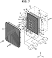
- FIG. 7 is a perspective view schematically illustrating the inside of the air conditioner according to an embodiment.
- FIG. 8 is a cross-sectional view of a portion of the air conditioner according to an embodiment.
- FIG. 9 is a cross-sectional view illustrating movement of ions in FIG. 8 .
- the cabinet 11 may be indicated by a dotted line and thus a configuration provided inside the housing 10 may be seen.
- the charger 60 may further include a downstream electrode 91.
- the downstream electrode 91 may be grounded on the ground 52.
- the downstream electrode 91 may maintain a voltage of substantially 0V.
- the downstream electrode 91 may maintain a lower potential than the discharge electrode 61. Accordingly, a constant potential difference may be formed between the downstream electrode 91 and the discharge electrode 61. An electric field may be formed between the downstream electrode 91 and the discharge electrode 61. High-density ions may be generated between the discharge electrode 61 and the downstream electrode 91.
- the downstream electrode 91 may be disposed downstream of the discharge electrode 61 with respect to the first direction F.
- the downstream electrode 91 may be disposed between the discharge electrode 61 and the dust collector 80.
- the downstream electrode 91 may be disposed adjacent to the dust collector 80.
- the downstream electrode 91 may extend along the second direction in which the upstream electrode 71 extends.
- the downstream electrode 91 may extend along the Y-axis and/or Z-axis.
- the downstream electrode 91 may extend along various directions perpendicular to the first direction F on the Y-Z plane.
- the downstream electrode 91 may be disposed in parallel to the second direction in which the upstream electrode 71 is disposed. That is, the downstream electrode 91 may be disposed in parallel to the Y-axis and/or the Z-axis. The downstream electrode 91 may be disposed on the Y-Z plane to be parallel to the upstream electrode 71.
- the downstream electrode 91 may have a mesh shape.
- the downstream electrode 91 may have a plate shape. However, it is not limited thereto, and the downstream electrode 91 may have the same shape as the upstream electrode 71.
- a part or all of the downstream electrode 91 may include a conductive material.
- a part or all of the downstream electrode 91 may include a metal.
- At least a portion of the downstream electrode 91 may include a metal or a conductive material having electrical characteristics similar to a metal.
- electric field charging may occur due to an action between the downstream electrode 91 and the discharge electrode 61. Ions generated from the discharge electrode 61 may charge aerosols in the air between the discharge electrode 61 and the downstream electrode 91.
- the third space 57 may be a space inside the housing 10.
- the third space 57 may be an internal space of the suction panel 16.
- the third space 57 may be a space disposed downstream of the suction panel 16 with respect to the air flow path.
- the third space 57 may be a space located in the first direction F from the suction panel 16.
- the third space 57 may be a space between the discharge electrode 61 and the downstream electrode 91.
- the third space 57 may be a space located downstream of the discharge electrode 61.
- the third space 57 may be a space located upstream of the downstream electrode 91.
- Ions generated from the discharge electrode 61 may charge aerosols in the air in the third space 57.
- the aerosols charged in the third space 57 may be collected by the dust collector 80.
- some of the ions generated from the discharge electrode 61 may charge the aerosols in the air outside the housing 10 in the first space 55, and some of the other ions generated from the discharge electrode 61 may charge the aerosols in the air inside the housing 10 in the second space 56 and/or the third space 57. That is, because the aerosols are charged even in the third space 57, the residence time of the aerosols may become longer and thus high charging efficiency may be obtained.
- the charging efficiency may be increased.
- the downstream electrode 91 may increase the charging efficiency by causing electric field charging in the third space 57.
- the air conditioner 1 may have a slim structure.
- FIG. 10 is a rear-view illustrating an air conditioner according to an embodiment.
- FIG. 11 is a rear-view illustrating an air conditioner according to an embodiment.
- FIG. 12 is a rear-view illustrating an air conditioner according to an embodiment.
- FIG. 13 is a rear-view illustrating an air conditioner according to an embodiment.
- FIG. 14 is a rear-view illustrating an air conditioner according to an embodiment.
- the suction panel 16 may include a cover portion 18.
- the cover portion 18 may include a discharge electrode cover portion 19.
- the discharge electrode cover portion 19 may be an area, which is provided in a position corresponding to the discharge electrode 61 with respect to the first direction F, in the cover portion 18.
- the discharge electrode cover portion 19 may be an area adjacent to the discharge electrode 61.
- the discharge electrode cover portion 19 may be an area covering the discharge electrode 61.
- the discharge electrode cover portion 19 may form a partial area of the cover portion 18.
- the discharge electrode cover portion 19 may be provided in the same shape as other areas of the cover portion 18. That is, the discharge electrode cover portion 19 may be provided without a hole separately formed to expose the discharge electrode 61 to the outside.
- the discharge electrode cover portion 19 may be formed by being connected to other areas of the cover portion 18, and thus the cover portion 18 may be provided in a uniform pattern over the entire area. Accordingly, aesthetics may be improved by increasing the degree of freedom in the design of the suction panel 16.
- the upstream electrode 71 may have a square ring shape.
- the electrode member 72 may have a square ring shape, and the hollow 75 may have a square shape.
- the discharge electrode 61 may be disposed in a position corresponding to approximately the center of the upstream electrode 71.
- the upstream electrode 71 may be provided to maximize an area covering the suction panel 16 in order to maintain an electric potential of the suction panel 16.
- An edge 73 of the electrode member 72 may have a round shape. Accordingly, when the discharge electrode 61 generates ions, it is possible to prevent a state in which an electric field is concentrated on a sharp specific part so as to generate a spark.
- R may be a diameter of a cross section of the upstream electrode 71. That is, R may be a diameter of a cross section of the upstream electrode 71 in a direction perpendicular to the second direction. R may be a diameter of a circle that is a cross section of the upstream electrode 71.
- D1 may be a distance between the upstream electrode 71 and the discharge electrode 61.
- D1 may be a distance between the center of the upstream electrode 71 in the second direction and one end of the brush 62 of the discharge electrode 61.
- D1 may be a distance between the upstream electrode 71 and the discharge electrode 61 with respect to the first direction F.
- D1 may be a vertical distance between the upstream electrode 71 and the discharge electrode 61.
- D2 may be a distance between the downstream electrode 91 and the discharge electrode 61. D2 may be a distance between one end of the brush 62 and the downstream electrode 91 that correspondingly disposed toward the one end of the brush 62. D2 may be a distance between the downstream electrode 91 and the discharge electrode 61 with respect to the first direction F. D2 may be a vertical distance between the downstream electrode 91 and the discharge electrode 61.
- a relationship between R and D1 may be provided in a range of 0.06 ⁇ R (mm) / D1 (mm) ⁇ 0.1.
- a relationship between D2 and the first voltage may be provided in a range of 2 ⁇ D2 (mm) / first voltage (kV) ⁇ 8.
- a charging efficiency of aerosols in the air may be improved under these conditions.
- the disclosure is not limited thereto.
- S1 may be a length of a side of the upstream electrode 71.
- S1 may be a length of a side when the upstream electrode 71 is provided in a rectangular ring shape.
- S1 may be a length at which the electrode member 72 of the upstream electrode 71 extends in the second direction.
- a relationship between S1 and D1 may be provided in a range of 2.5 ⁇ S1 (mm) / D1 (mm) ⁇ 6.
- a relationship between D1 and the first voltage may be provided in the range of 3 ⁇ D1 (mm)/first voltage (kV) ⁇ 10..
- a charging efficiency of aerosols in the air may be improved under these conditions.
- the disclosure is not limited thereto.
- the upstream electrode 71 may have a circular ring shape.
- the electrode member 72 may have a circular ring shape, and the hollow 75 may have a circular shape.
- the discharge electrode 61 may be disposed in a position corresponding to approximately the center of the upstream electrode 71.
- S2 may be a length of the diameter of the upstream electrode 71.
- S2 may be a length of a diameter when the upstream electrode 71 is provided in a circular ring shape.
- a relationship between S2 and D1 may be provided in a range of 2.5 ⁇ S2 (mm) / D1 (mm) ⁇ 6.
- a relationship between D1 and the first voltage may be provided in a range of 3 ⁇ D1 (mm)/first voltage (kV) ⁇ 10.
- the disclosure is not limited thereto.
- the upstream electrode 71 may include a first upstream electrode 71a disposed toward the first discharge electrode 61a and a second upstream electrode 71b disposed toward the second discharge electrode 61b and disposed adjacent to the first upstream electrode 71a.
- the second upstream electrode 71b may extend from the first upstream electrode 71a.
- An electrode member 72b of the second upstream electrode 71b may extend from an electrode member 72a of the first upstream electrode 71a.
- the first upstream electrode 71a and the second upstream electrode 71b may share an electrode member 72c.
- the first upstream electrode 71a and the second upstream electrode 71b may share at least a portion of the electrode member 72.
- the first upstream electrode 71a and the second upstream electrode 71b may be integrally formed.
- the first upstream electrode 71a and the second upstream electrode 71b may be formed in a lattice shape.
- the upstream electrode 71 may be formed in a quadrangular lattice shape, and referring to FIG. 13 , the upstream electrode 71 may be formed in a hexagonal lattice shape.
- the upstream electrode 71 may be formed in various polygonal or circular shapes to cover the discharge electrode 61.
- the upstream electrode 71 may have a cylindrical shape.
- the upstream electrode 71 may have a rod shape.
- the electrode member 72 may extend to correspond to the length of the suction panel 16. However, the disclosure is not limited thereto, and the length of the electrode member 72 extending along the suction panel 16 may be implemented in various ways.
- FIG. 15 is a perspective view illustrating an air conditioner according to an embodiment.
- An air conditioner 100 may include a wall-mounted air conditioner 100 installed on a wall.
- the air conditioner 100 may include a housing 110.
- the housing 110 may have a substantially rectangular parallelepiped shape.
- the housing 110 may include a suction panel 160 provided to allow outside air to flow into the air conditioner 100.
- the housing 110 may include a discharge panel 150 provided to discharge air, which is sucked into the housing 110 through the suction panel 160, to an outside.
- a first direction F in which air flows may be a direction from top to bottom. That is, the first direction F may be a direction along the Z-axis.
- the suction panel 160 may extend along a second direction.
- the second direction may be a direction along the Y-axis.
- the suction panel 160 may include a cover portion 180 and an opening 170.
- the cover portion 180 may include a plurality of ribs. The plurality of ribs may extend along various directions.
- the cover portion 180 may be formed along the second direction.
- the cover portion 180 may have a linear shape.
- the cover portion 180 may be elongated in the left and right direction.
- the cover portion 180 may extend in a straight line.
- the cover portion 180 may extend along the Y-axis.
- the cover portion 180 may be provided in plurality.
- the cover portions 180 may be disposed spaced apart from each other.
- the cover portions 180 may be spaced apart along the X-axis.
- the disclosure is not limited thereto, and the cover portion 180 may be provided as a single piece.
- the discharge panel 150 may include a discharge port 151.
- the discharge port 151 may be provided in plurality and have a circular shape.
- the disclosure is not limited thereto, and the discharge port of the air conditioner 100 may be provided at a lower portion of the housing 110.
- FIG. 16 is a perspective view schematically illustrating an inside of the air conditioner according to an embodiment.
- FIG. 17 is a cross-sectional view illustrating movement of ions in a portion of the air conditioner according to an embodiment.
- a discharge electrode 610 may include a first discharge electrode 610a and a second discharge electrode 610b spaced apart from the first discharge electrode 610a.
- the first discharge electrode 610a and the second discharge electrode 610b may be arranged along an extension direction of the cover portion 180 and/or the opening 170.
- the first discharge electrode 610a and the second discharge electrode 610b may be spaced apart from each other along the extension direction of the cover portion 180 and/or the opening 170.
- the first discharge electrode 610a and the second discharge electrode 610b may be arranged along the Y-axis.
- An upstream electrode 710 may be provided in a shape corresponding to the cover portion 180 and/or the opening 170.
- the upstream electrode 710 may extend along the direction in which the cover portion 180 extends.
- the upstream electrode 710 may extend along the Y-axis.
- the upstream electrode 710 may be provided to cover the first discharge electrode 610a and the second discharge electrode 610b.
- the upstream electrode 710 may extend along the arrangement direction of the first discharge electrode 610a and the second discharge electrode 610b.
- the upstream electrode 710 may have a cylindrical shape.
- the upstream electrode 710 may have a rod shape.
- the upstream electrode 710 may have a linear shape.
- the upstream electrode 710 may be disposed on the Z-axis with the discharge electrode 610.
- the cover portion 180, the upstream electrode 710, and the discharge electrode 610 may be arranged in a line.
- the electrostatic precipitator may have a slim design even when the cover portion 180 and/or the opening 170 have a linear shape.
- the plurality of discharge electrodes 610a and 610b arranged along the arrangement direction of the cover 180 and/or the opening 170, and a single upstream electrode 710 provided to cover the plurality of discharge electrodes 610a and 610b are illustrated as an example, but is not limited thereto.
- the discharge electrode 610 may include a third discharge electrode (not shown) spaced apart from the first discharge electrode 610a along the X-axis.
- the third discharge electrode (not shown) may be arranged along the arrangement direction of the plurality of cover portions 180 and/or the opening 170 from the first discharge electrode 610a.
- the upstream electrode 710 may include an upstream electrode (not shown) covering the third discharge electrode (not shown).
- the upstream electrode 710 may be provided in plurality.
- FIG. 18 is a perspective view schematically illustrating the inside of the air conditioner according to an embodiment.
- the upstream electrode 710 may include a first upstream electrode 710a and a second upstream electrode 710b spaced apart from the first upstream electrode 710a.
- the first upstream electrode 710a and the second upstream electrode 710b may be arranged to allow the discharge electrode 610 to be interposed therebetween. That is, the first upstream electrode 710a and the second upstream electrode 710b may be alternately disposed with the discharge electrode 610 interposed therebetween.
- the first upstream electrode 710a and the second upstream electrode 710b may be arranged in parallel with each other.
- the first upstream electrode 710a and the second upstream electrode 710b may be arranged along the X-axis.
- a distance between the first upstream electrode 710a and the discharge electrode 610 may be the same as a distance between the second upstream electrode 710b and the discharge electrode 610. However, the disclosure is not limited thereto, and the distance between the first upstream electrode 710a and the discharge electrode 610 may be greater or less than the distance between the second upstream electrode 710b and a discharge electrode 610.
- Ions generated from the discharge electrode 610 may be directed to the first upstream electrode 710a or the second upstream electrode 710b.
- Ions generated from the discharge electrode 610 may move to the first upstream electrode 710a or the second upstream electrode 710b, and thus the ions may be emitted into a wider space. Accordingly, ions may be uniformly sprayed out of the housing 110.
- FIG. 19 is a perspective view schematically illustrating the inside of the air conditioner according to an embodiment.
- the upstream electrode 710 may include the first upstream electrode 710a and the second upstream electrode 710b spaced apart from the first upstream electrode 710a.
- the first upstream electrode 710a and the second upstream electrode 710b may be spaced apart from each other along the extension direction of the cover portion 180.
- the first upstream electrode 710a and the second upstream electrode 710b may be arranged along the Y-axis.
- the first upstream electrode 710a and the second upstream electrode 710b may be arranged to allow the discharge electrode 610 to be interposed therebetween.
- Ions generated from the discharge electrode 610 may move to the first upstream electrode 710a or the second upstream electrode 710b. In addition, because an empty space is formed in front of the discharge electrode 610, ions generated from the discharge electrode 610 may be more easily sprayed toward the outside of the housing 110.
- FIGS. 11 to 19 may be combined with the embodiments of FIGS. 4 to 9 .
- an air conditioner comprises a housing (10) including a suction panel (16); a fan (31) disposed inside the housing (10) and configured to generate an air flow which is sucked into the housing through the suction panel to flow in a first direction from upstream to downstream, the suction panel (16) being perpendicular to the first direction; and an electrostatic precipitator (50) disposed inside the housing and including: a discharge electrode (61) configured to receive a voltage and to generate ions toward the suction panel, and an upstream electrode (71) disposed upstream of the discharge electrode with respect to the first direction, grounded to form an electric field with the discharge electrode (61), and disposed between the discharge electrode (71) and the suction panel 16), wherein at least a portion of the ions generated from the discharge electrode (61) are passed through the suction panel (16) so as to charge aerosols in air outside the housing (10).
- the upstream electrode (71) may extend along a plane perpendicular to the first direction to at least partially cover the suction panel (16).
- the upstream electrode (71) may include a hollow (75), and an electrode member (72) forming an outer circumference of the hollow and having a length extending along the plane perpendicular to the first direction.
- the discharge electrode (61) may include a first discharge electrode (61a) , and a second discharge (61b) electrode spaced apart from the first discharge electrode (61a) in a second direction perpendicular to the first direction
- the upstream electrode (71) includes: a first upstream electrode (71a) disposed so that a center of the first upstream electrode is disposed in a position corresponding to the first discharge electrode (61a) along the first direction, and a second upstream electrode (71b) disposed so that a center of the second upstream electrode is disposed in a position corresponding to the second discharge electrode (61b) along the first direction, the second upstream electrode (71b) being spaced apart from and disposed adjacent to the first upstream electrode (71a), and the air conditioner further may comprise: a through hole (76) extending between the first upstream electrode (71a) and the second upstream electrode (71b).
- the discharge electrode(61) may include a first discharge electrode (61a), and a second discharge electrode(61b) spaced apart from the first discharge electrode (61a) in a second direction perpendicular to the first direction
- the upstream electrode (71) may include a first upstream electrode (71a) disposed so that a center of the first upstream electrode is disposed in a position corresponding to the first discharge electrode (61a) along the first direction, and a second upstream electrode (71b) disposed so that a center of the second upstream electrode (71b) is disposed in a position corresponding to the second discharge electrode (61b) along the first direction, the second upstream electrode (71b) disposed adjacent to the first upstream electrode (71a), and the electrode member (72) of the second upstream electrode extends from the electrode member of the first upstream electrode.
- the electrode member (72) may be configured in a polygonal ring shape.
- the electrode member (72) may be configured in a circular ring shape.
- a cross section of the electrode member (72) may have a circular shape.
- the upstream electrode (71) may be configured in a rod shape.
- the upstream electrode (71) may be disposed to be in contact with the suction panel.
- the electrostatic precipitator (50) may further include a downstream electrode (91) disposed downstream of the discharge electrode (61) with respect to the first direction, and the downstream electrode may be grounded to form an electric field with the discharge electrode.
- the downstream electrode (91) may have a mesh shape.
- At least a portion of the downstream electrode (91) may include a conductive material.
- the suction panel (16) may include a cover portion (18) disposed toward the electrostatic precipitator (50) to prevent the electrostatic precipitator from being exposed to the outside of the housing (10).
- the cover portion (16) may include a discharge electrode cover portion (19) provided at a position corresponding to the discharge electrode with respect to the first direction.
- an electrostatic precipitator (50) includes a discharge electrode (61) disposed in an air flow path and configured to generate ions in a direction opposite to one direction in which air flows from upstream to downstream, and an upstream electrode (71) disposed upstream of the discharge electrode with respect to the one direction.
- the upstream electrode (71) may be grounded to maintain a potential difference with the discharge electrode (61), and disposed toward the discharge electrode (61) with respect to the one direction.
- the electrostatic precipitator may include a downstream electrode (91) disposed downstream of the discharge electrode with respect to the one direction.
- the downstream electrode (91) may be grounded to maintain a potential difference with the discharge electrode (61), and may be disposed toward the discharge electrode (61) with respect to the one direction.
- the upstream electrode (71) may include a hollow (75) and an electrode member (72) forming an outer circumference of the hollow and disposed toward the discharge electrode (61) with respect to the one direction.
- the discharge electrode (61) may include a first discharge electrode (61a), and a second discharge electrode (61b) disposed spaced apart from the first discharge electrode along the second direction.
- the upstream electrode (71) may include a first upstream electrode (71a) disposed to allow a center of the first upstream electrode with respect to the other direction, which is perpendicular to the one direction, to be disposed toward the first discharge electrode along the one direction, and a second upstream electrode (71b) disposed to allow a center of the second upstream electrode with respect to the other direction to be disposed toward the second discharge electrode along the one direction, the second upstream electrode (71b) spaced apart from and disposed adjacent to the first upstream electrode(71a).
- the electrostatic precipitator (50) may further include a through hole (76) extending from an electrode member (72) of the first upstream electrode (71a) to an electrode member (72) of the second upstream electrode (71b).
- ions generated by a discharge electrode may be sprayed to an outside of a housing to improve an air charging efficiency.
- a charging efficiency of air outside and inside a housing may be improved.
- aesthetics may be improved by increasing a degree of freedom in design of an air conditioner.
- a degree of freedom in installation of an air conditioner may be increased.
Landscapes
- Engineering & Computer Science (AREA)
- Chemical & Material Sciences (AREA)
- Combustion & Propulsion (AREA)
- Mechanical Engineering (AREA)
- General Engineering & Computer Science (AREA)
- Electrostatic Separation (AREA)
Applications Claiming Priority (4)
| Application Number | Priority Date | Filing Date | Title |
|---|---|---|---|
| KR20220114541 | 2022-09-08 | ||
| KR1020220185037A KR20240035300A (ko) | 2022-09-08 | 2022-12-26 | 공기 조화기 및 전기 집진 장치 |
| KR1020230093448A KR20240035316A (ko) | 2022-09-08 | 2023-07-18 | 공기 조화기 및 전기 집진 장치 |
| PCT/KR2023/011587 WO2024053875A1 (fr) | 2022-09-08 | 2023-08-07 | Climatiseur et dispositif électrique de collecte de poussière |
Publications (2)
| Publication Number | Publication Date |
|---|---|
| EP4502479A1 true EP4502479A1 (fr) | 2025-02-05 |
| EP4502479A4 EP4502479A4 (fr) | 2025-07-30 |
Family
ID=90141909
Family Applications (1)
| Application Number | Title | Priority Date | Filing Date |
|---|---|---|---|
| EP23863356.4A Pending EP4502479A4 (fr) | 2022-09-08 | 2023-08-07 | Climatiseur et dispositif électrique de collecte de poussière |
Country Status (2)
| Country | Link |
|---|---|
| US (1) | US20240085039A1 (fr) |
| EP (1) | EP4502479A4 (fr) |
Families Citing this family (1)
| Publication number | Priority date | Publication date | Assignee | Title |
|---|---|---|---|---|
| US20250375773A1 (en) * | 2024-06-07 | 2025-12-11 | Airquality Technology (Shanghai) Co., Ltd. | Electrostatic charging device and assembly method thereof |
Family Cites Families (24)
| Publication number | Priority date | Publication date | Assignee | Title |
|---|---|---|---|---|
| FR883953A (fr) * | 1941-04-28 | 1943-07-28 | Heinrich Koppers Ges M B H | Dispositif de traitement de gaz par décharges électriques |
| GB1046652A (en) * | 1961-05-26 | 1966-10-26 | Gen Electric | Apparatus for electrostatic precipitation |
| GB2154156B (en) * | 1984-01-24 | 1987-10-21 | Nippon Light Metal Co | Electrostatic air cleaner |
| JPS629021U (fr) * | 1985-06-29 | 1987-01-20 | ||
| JPH0544240U (ja) * | 1991-11-25 | 1993-06-15 | エイチ・イー・シー株式会社 | 電気集塵装置及びこれを用いる空気清浄機 |
| SE9200515L (sv) * | 1992-02-20 | 1993-07-12 | Tl Vent Ab | Tvaastegs elektrofilter |
| KR100732421B1 (ko) * | 2002-12-23 | 2007-06-27 | 삼성전자주식회사 | 공기 정화기 |
| GB0408910D0 (en) * | 2004-04-22 | 2004-05-26 | Darwin Technology Ltd | Device for air cleaning |
| JP5304096B2 (ja) * | 2007-10-29 | 2013-10-02 | ダイキン工業株式会社 | 荷電装置及び空気処理装置 |
| JP2009106827A (ja) * | 2007-10-29 | 2009-05-21 | Daikin Ind Ltd | 空気処理装置 |
| CN102186594B (zh) * | 2008-10-20 | 2015-11-25 | 开利公司 | 采用后纤维充电的电加强空气过滤系统 |
| KR101860489B1 (ko) * | 2009-10-28 | 2018-07-05 | 삼성전자주식회사 | 전기집진장치 및 이를 포함하는 공기청정기 |
| JP6046979B2 (ja) * | 2012-10-30 | 2016-12-21 | アマノ株式会社 | 電気集塵機 |
| JP5461736B1 (ja) * | 2013-05-13 | 2014-04-02 | 株式会社 片野工業 | イオン・オゾン風発生装置及び方法 |
| JP6317558B2 (ja) * | 2013-09-30 | 2018-04-25 | アマノ株式会社 | 電気集塵機 |
| KR102201298B1 (ko) * | 2015-02-17 | 2021-01-11 | 한온시스템 주식회사 | 전기집진용 대전장치 |
| JP6460890B2 (ja) * | 2015-04-06 | 2019-01-30 | アマノ株式会社 | 荷電装置及び電気集塵機 |
| JP6260915B2 (ja) * | 2016-11-18 | 2018-01-17 | アマノ株式会社 | 電気集塵機 |
| DE102018205332A1 (de) * | 2018-04-10 | 2019-10-10 | BSH Hausgeräte GmbH | Elektrostatische Filtereinheit und Lüftungsvorrichtung mit elektrostatischer Filtereinheit |
| KR102599228B1 (ko) * | 2018-12-28 | 2023-11-08 | 한온시스템 주식회사 | 대전부 및 이를 포함하는 전기집진장치 |
| US12269045B2 (en) * | 2019-04-02 | 2025-04-08 | Samsung Electronics Co., Ltd. | Electrostatic charger and electrostatic precipitator |
| DE102020107419A1 (de) * | 2020-03-18 | 2021-09-23 | Oliver Schmitz | Elektroabscheider mit Stromaufwärts-Kollektorelement |
| FI130711B1 (fi) * | 2020-05-15 | 2024-02-05 | Genano Oy | Ilmanpuhdistuslaite, järjestely ja menetelmä materiaalin poistamiseksi kaasuvirrasta |
| JP7665368B2 (ja) * | 2021-03-23 | 2025-04-21 | アマノ株式会社 | 荷電装置及び空気清浄機 |
-
2023
- 2023-08-07 EP EP23863356.4A patent/EP4502479A4/fr active Pending
- 2023-08-17 US US18/235,185 patent/US20240085039A1/en active Pending
Also Published As
| Publication number | Publication date |
|---|---|
| EP4502479A4 (fr) | 2025-07-30 |
| US20240085039A1 (en) | 2024-03-14 |
Similar Documents
| Publication | Publication Date | Title |
|---|---|---|
| US5474599A (en) | Apparatus for electrostatically cleaning particulates from air | |
| EP2039432B1 (fr) | Collecteur de poussiere | |
| KR100914364B1 (ko) | 전기 집진 장치 및 그것을 이용한 송풍 장치 | |
| US7655076B2 (en) | Device for air cleaning | |
| EP0626886B1 (fr) | Filtre electrostatique a deux etages | |
| KR101651034B1 (ko) | 전기집진기 및 그 전기집진기를 포함하는 공기청정 시스템 | |
| US7090717B2 (en) | Air purifier | |
| KR101082713B1 (ko) | 집진장치 | |
| EP4502479A1 (fr) | Climatiseur et dispositif électrique de collecte de poussière | |
| KR101981011B1 (ko) | 공기청정기 | |
| KR20240035316A (ko) | 공기 조화기 및 전기 집진 장치 | |
| KR102611401B1 (ko) | 차량용 공기조화기 | |
| US20240286146A1 (en) | Electronic dust collecting device | |
| KR20240035300A (ko) | 공기 조화기 및 전기 집진 장치 | |
| JPH04135661A (ja) | 電気集塵器 | |
| KR20250031566A (ko) | 공기 조화기 | |
| KR20250090140A (ko) | 공기 조화기 | |
| KR20240155553A (ko) | 집진 시트 및 전기 집진 장치 | |
| KR20230090130A (ko) | 전기 집진 장치 및 이를 구비한 가전 기기 | |
| JP2005270980A (ja) | 電気集塵装置およびそれを用いた送風装置 | |
| JP2010172854A (ja) | 集塵装置 |
Legal Events
| Date | Code | Title | Description |
|---|---|---|---|
| STAA | Information on the status of an ep patent application or granted ep patent |
Free format text: STATUS: THE INTERNATIONAL PUBLICATION HAS BEEN MADE |
|
| PUAI | Public reference made under article 153(3) epc to a published international application that has entered the european phase |
Free format text: ORIGINAL CODE: 0009012 |
|
| STAA | Information on the status of an ep patent application or granted ep patent |
Free format text: STATUS: REQUEST FOR EXAMINATION WAS MADE |
|
| 17P | Request for examination filed |
Effective date: 20241031 |
|
| AK | Designated contracting states |
Kind code of ref document: A1 Designated state(s): AL AT BE BG CH CY CZ DE DK EE ES FI FR GB GR HR HU IE IS IT LI LT LU LV MC ME MK MT NL NO PL PT RO RS SE SI SK SM TR |
|
| A4 | Supplementary search report drawn up and despatched |
Effective date: 20250626 |
|
| RIC1 | Information provided on ipc code assigned before grant |
Ipc: F24F 8/192 20210101AFI20250620BHEP Ipc: F24F 8/80 20210101ALI20250620BHEP Ipc: F24F 13/28 20060101ALI20250620BHEP Ipc: F24F 13/20 20060101ALI20250620BHEP Ipc: B03C 3/12 20060101ALI20250620BHEP Ipc: B03C 3/36 20060101ALI20250620BHEP Ipc: B03C 3/38 20060101ALI20250620BHEP Ipc: B03C 3/45 20060101ALI20250620BHEP Ipc: B03C 3/09 20060101ALI20250620BHEP Ipc: B03C 3/32 20060101ALI20250620BHEP Ipc: B03C 3/41 20060101ALI20250620BHEP Ipc: B03C 3/47 20060101ALI20250620BHEP Ipc: F24F 130/20 20180101ALI20250620BHEP |
|
| DAV | Request for validation of the european patent (deleted) | ||
| DAX | Request for extension of the european patent (deleted) |