EP4502772A1 - Accessoires passifs - Google Patents
Accessoires passifs Download PDFInfo
- Publication number
- EP4502772A1 EP4502772A1 EP23306333.8A EP23306333A EP4502772A1 EP 4502772 A1 EP4502772 A1 EP 4502772A1 EP 23306333 A EP23306333 A EP 23306333A EP 4502772 A1 EP4502772 A1 EP 4502772A1
- Authority
- EP
- European Patent Office
- Prior art keywords
- user
- magnetic object
- contact
- manipulation feature
- magnetic
- Prior art date
- Legal status (The legal status is an assumption and is not a legal conclusion. Google has not performed a legal analysis and makes no representation as to the accuracy of the status listed.)
- Pending
Links
Images





Classifications
-
- G—PHYSICS
- G06—COMPUTING OR CALCULATING; COUNTING
- G06F—ELECTRIC DIGITAL DATA PROCESSING
- G06F3/00—Input arrangements for transferring data to be processed into a form capable of being handled by the computer; Output arrangements for transferring data from processing unit to output unit, e.g. interface arrangements
- G06F3/01—Input arrangements or combined input and output arrangements for interaction between user and computer
- G06F3/03—Arrangements for converting the position or the displacement of a member into a coded form
- G06F3/033—Pointing devices displaced or positioned by the user, e.g. mice, trackballs, pens or joysticks; Accessories therefor
- G06F3/0354—Pointing devices displaced or positioned by the user, e.g. mice, trackballs, pens or joysticks; Accessories therefor with detection of two-dimensional [2D] relative movements between the device, or an operating part thereof, and a plane or surface, e.g. 2D mice, trackballs, pens or pucks
-
- G—PHYSICS
- G01—MEASURING; TESTING
- G01R—MEASURING ELECTRIC VARIABLES; MEASURING MAGNETIC VARIABLES
- G01R33/00—Arrangements or instruments for measuring magnetic variables
- G01R33/02—Measuring direction or magnitude of magnetic fields or magnetic flux
-
- G—PHYSICS
- G01—MEASURING; TESTING
- G01V—GEOPHYSICS; GRAVITATIONAL MEASUREMENTS; DETECTING MASSES OR OBJECTS; TAGS
- G01V3/00—Electric or magnetic prospecting or detecting; Measuring magnetic field characteristics of the earth, e.g. declination, deviation
- G01V3/08—Electric or magnetic prospecting or detecting; Measuring magnetic field characteristics of the earth, e.g. declination, deviation operating with magnetic or electric fields produced or modified by objects or geological structures or by detecting devices
-
- G—PHYSICS
- G06—COMPUTING OR CALCULATING; COUNTING
- G06F—ELECTRIC DIGITAL DATA PROCESSING
- G06F3/00—Input arrangements for transferring data to be processed into a form capable of being handled by the computer; Output arrangements for transferring data from processing unit to output unit, e.g. interface arrangements
- G06F3/01—Input arrangements or combined input and output arrangements for interaction between user and computer
- G06F3/03—Arrangements for converting the position or the displacement of a member into a coded form
- G06F3/033—Pointing devices displaced or positioned by the user, e.g. mice, trackballs, pens or joysticks; Accessories therefor
- G06F3/0346—Pointing devices displaced or positioned by the user, e.g. mice, trackballs, pens or joysticks; Accessories therefor with detection of the device orientation or free movement in a three-dimensional [3D] space, e.g. 3D mice, 6-DOF [six degrees of freedom] pointers using gyroscopes, accelerometers or tilt-sensors
-
- G—PHYSICS
- G06—COMPUTING OR CALCULATING; COUNTING
- G06F—ELECTRIC DIGITAL DATA PROCESSING
- G06F3/00—Input arrangements for transferring data to be processed into a form capable of being handled by the computer; Output arrangements for transferring data from processing unit to output unit, e.g. interface arrangements
- G06F3/01—Input arrangements or combined input and output arrangements for interaction between user and computer
- G06F3/03—Arrangements for converting the position or the displacement of a member into a coded form
- G06F3/033—Pointing devices displaced or positioned by the user, e.g. mice, trackballs, pens or joysticks; Accessories therefor
- G06F3/0354—Pointing devices displaced or positioned by the user, e.g. mice, trackballs, pens or joysticks; Accessories therefor with detection of two-dimensional [2D] relative movements between the device, or an operating part thereof, and a plane or surface, e.g. 2D mice, trackballs, pens or pucks
- G06F3/03543—Mice or pucks
-
- G—PHYSICS
- G06—COMPUTING OR CALCULATING; COUNTING
- G06F—ELECTRIC DIGITAL DATA PROCESSING
- G06F3/00—Input arrangements for transferring data to be processed into a form capable of being handled by the computer; Output arrangements for transferring data from processing unit to output unit, e.g. interface arrangements
- G06F3/01—Input arrangements or combined input and output arrangements for interaction between user and computer
- G06F3/03—Arrangements for converting the position or the displacement of a member into a coded form
- G06F3/033—Pointing devices displaced or positioned by the user, e.g. mice, trackballs, pens or joysticks; Accessories therefor
- G06F3/0354—Pointing devices displaced or positioned by the user, e.g. mice, trackballs, pens or joysticks; Accessories therefor with detection of two-dimensional [2D] relative movements between the device, or an operating part thereof, and a plane or surface, e.g. 2D mice, trackballs, pens or pucks
- G06F3/03545—Pens or stylus
Definitions
- the present disclosure relates to the technical field of determining and/or tracking a location of passive accessories, more specifically to a user-borne device operable on an interaction surface, to a system for determining a manipulation of a user-borne device, and to a method for determining a manipulation of a user-borne device.
- the provision of a plurality of magnetometers allows to measure a magnetic field associated with a magnetic object arranged in or coupled to the user-borne device.
- the user-borne devices using this technology may be electronically and/or electrically passive. More specifically, electrically passive means that the user-borne device may not comprise a power source (e.g., batteries) and/or means to receive power (e.g., wireless power transmission via an inductive coil) for powering an electronic feature of the user-borne device. Electronically passive means that no computation or processing occurs (or happens) on the user-borne device.
- the magnetometer measurements enable determining and/or tracking of the location of the magnetic object within a sensing volume created by the plurality of magnetometers.
- the magnetic object may be arranged within a writing device (e.g., a stylus) which may be operated by a user on a writing support during a user operation. Based on the magnetic field measurements associated with the magnetic object, a location of the writing device on the writing support may be determined.
- a writing device e.g., a stylus
- the determination and/or tracking of a location of a user-borne device with a plurality of magnetometers may require the definition of an interaction surface on which the user-borne device may be operated or with respect to which the location of the user-borne device may be determined.
- the user-borne device may be operated directly on the interaction surface, or at a distance to the interaction surface (e.g., in the air).
- manufacturing tolerances e.g., manufacturing inaccuracies of the arrangement of the plurality of magnetometers may occur and/or the interaction surface may not be always known or defined accurately with respect to the plurality of magnetometers and/or with respect to the user-borne device.
- the plurality of magnetometers may be tilted in an unknown way relative to the interaction surface (and vice versa), e.g., when the user-borne device is operated on a surface (i.e., the interaction surface) that is different from a surface of the device that includes the plurality of magnetometers.
- the interaction surface and its location i.e., the interaction surface location
- the interaction surface location may be changed arbitrarily by a user (e.g., the user-borne device may be operated on a book used as interaction surface, then on a table and so on).
- the interaction surface location may be somehow assumed or approximated.
- the applicability of the tracking and/or location determination of the user-borne device may be limited to very specific embodiments and arrangements of a user-borne device relative to a plurality of magnetometers.
- the object of the present disclosure is to provide a user-borne device operable on an interaction surface, a system and a method for determining a manipulation of a user-borne device, which enable a tracking and/or a location determination of a user-borne device manipulated within a sensing volume with increased accuracy and reliability, and more specifically which enable an accurate and reliable determination of the interaction surface.
- the present disclosure relates to a user-borne device operable on an interaction surface as defined in claim 1, a system for determining a manipulation of a user-borne device as defined in claim 12, and a computer-implemented method for determining a manipulation of a user-borne device as defined in claim 13. Furthermore, the present disclosure relates to a computer system configured to execute the computer-implemented method as defined in claim 14, a computer program configured to execute the computer-implemented method as defined in claim 15, and a computer-readable medium or signal storing the computer program as defined in claim 16.
- the dependent claims depict advantageous embodiments of the present disclosure.
- a user-borne device operable on an interaction surface comprises a housing, a magnetic object coupled to the housing, and at least one contact manipulation feature movably coupled to the housing.
- the at least one contact manipulation feature is configured to interact with the magnetic object such that an actuation of the at least one contact manipulation feature causes a transition of the magnetic object from a first state to a second state.
- the transition from the first state to the second state is indicative of a contact event of the user-borne device with the interaction surface.
- the transition may be detected by a plurality of magnetometers and may be associated with a contact event of the user-borne device with the interaction surface.
- Transition means that the magnetic object provides a change from the first state to the second state that is detectable with the plurality of magnetometers.
- the interaction surface more specifically the interaction surface location, may be defined in an accurate and/or reliable way. More specifically, based on an actuation of the at least one contact manipulation feature, the transition from the first state to the second state may be detected and the contact event may be determined which in turn may be applied to precisely derive the interaction surface location. This may lead to an improved determination of a location and/or tracking of the user-borne device relative to the interaction surface and/or the plurality of magnetometers, more specifically with increased accuracy and reliability.
- At least one trigger event which will be described in detail below (e.g., associated with the additional functions) may be controlled by the user-borne device in an improved manner, as it may be coupled with the detectable transition of the magnetic object.
- the contact event and/or the at least one trigger event may be initiated by a user manipulation of the user-borne device within a sensing volume.
- the contact event may be initiated by a contact of the user-borne device, more specifically of the at least one contact manipulation feature, with the interaction surface and within the sensing volume.
- the contact event and/or the at least one trigger event may cause an action and/or may be used to control an action in a digital environment (i.e., an environment which is controlled by a computer or a network of computers), more specifically a virtual environment.
- the contact event may implement a user input or a physical contact of the at least one contact manipulation feature with the interaction surface, which may be used for a precise definition of the interaction surface (location).
- location may be used for a precise definition of the interaction surface (location).
- the magnetic object should be interpreted as at least one magnetic object and the contact event should be interpreted as at least one contact event.
- a system for determining a manipulation of a user-borne device comprises a user-borne device according to the first aspect of present disclosure, and a plurality of magnetometers.
- the plurality of magnetometers is configured to create a sensing volume and configured to measure a magnetic field created by the magnetic object.
- the system is configured to detect a transition of the magnetic object from a first state to a second state.
- the system is configured to determine a contact event of the user-borne device with the interaction surface based on the detected transition.
- the system may use the determined contact event to derive a definition of the interaction surface location with increased accuracy and reliability.
- the system may determine a location and/or tracking of the user-borne device relative to the interaction surface with increased accuracy and reliablity.
- Such a system may allow the tracking and/or location determination of a user-borne device, more specifically an electronically and/or electrically user-borne device, in at least five degrees of freedom with a magnetic object.
- a method for determining a manipulation of a user-borne device comprises obtaining magnetic field measurements associated with a magnetic field created by a magnetic object coupled to a housing of a user-borne device according to the first aspect of the present disclosure and measured with a plurality of magnetometers. The method further comprises detecting a transition of the magnetic object from a first state to a second state. The method further comprises determining a contact event of the user-borne device with the interaction surface based on the detected transition.
- the above-described effects and advantages for the system and the user-borne device may apply analogously to the method.
- the method for determining a manipulation of a user-borne device may be a computer-implemented method. Further aspects of the present disclosure relate to a computer system configured to execute the computer-implemented method, a computer program configured to execute the computer-implemented method and/or a computer-readable medium or signal storing the computer program.
- the determination (and/or tracking) of a location of a user-borne device 100 with a plurality of magnetometers 300 requires the definition of an interaction surface 210 on which the user-borne device 100 may be operated or with respect to which the location of the user-borne device may be determined.
- the transition may be detected by the plurality of magnetometers 300 and may be linked with a contact event of the user-borne device 100 with the interaction surface 210.
- Transition means that the magnetic object 110 provides a change from the first state to the second state that is detectable with the plurality of magnetometers.
- the interaction surface 210 more specifically the interaction surface location, may be defined in an accurate and/or reliable way.
- the transition from the first state to the second state may be detected and the contact event may be determined which in turn may be applied to precisely derive the interaction surface location.
- This may lead to an improved determination of a location and/or tracking of the user-borne device 100 relative to the interaction surface 210 and/or the plurality of magnetometers 300, more specifically with increased accuracy and reliability. This may be the case even when the interaction surface 210 and its location are initially unknown, and/or when the user operates the user-borne device 100 on different interaction surfaces or in the air (i.e., without physical contact with the interaction surface).
- the user-borne device 100 can be provided electronically and/or electrically passive. This may lead to lower costs and to a lower complexity of the user-borne device.
- additional functions can be integrated in the user-borne device 100 and application fields of the user-borne device 100 can be extended. At least one trigger event which will be described in detail below (e.g., associated with the additional functions) may be controlled by the user-borne device 100 in an improved manner, as it may be coupled with the detectable transition of the magnetic object 100.
- the contact event and/or the at least one trigger event may be initiated by a user manipulation of the user-borne device 100 within a sensing volume.
- the contact event may be initiated by a contact of the user-borne device 100, more specifically of the at least one contact manipulation feature 170, with the interaction surface 210 and within the sensing volume.
- the contact event and/or the at least one trigger event may cause an action and/or may be used to control an action in a digital environment (i.e., an environment which is controlled by a computer or a network of computers), more specifically a virtual environment.
- the contact event may implement a user input or a physical contact of the at least one contact manipulation feature 170 with the interaction surface 210, which may be used for a precise definition of the interaction surface (location).
- the magnetic object 110 should be interpreted as at least one magnetic object and the contact event should be interpreted as at least one contact event.
- the magnetic object 110 described herein may be at least one magnetic object 110.
- the user-borne device 100 may comprise additional magnetic objects.
- the embodiments described herein for the magnetic object 110 may also apply for the additional magnetic objects.
- the magnetic object 110 may be a permanent magnet.
- the magnetic object 110 may be configured to generate a non-zero magnetic field. It may comprise a paramagnetic or diamagnetic material.
- the magnetic object 110 may comprise a ferromagnetic material or a ferrimagnetic material.
- the magnetic object 110 may be configured to create or generate a symmetric magnetic field 115, more specifically wherein the magnetic field 115 may be rotationally symmetric.
- the user-borne device 100 may a computer mouse, a keyboard, a toy, a stylus, or a dial.
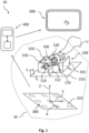
- the user-borne device 100 may be operable on an interaction surface 210.
- a movement of the user-borne device 100 on the interaction surface 10 is illustrated.
- the user-borne device 100 may be translatable on the interaction surface 210 along the first device axis x d and/or the second device axis y d .
- the user-borne device 100 may be a computer mouse.
- the user-borne device 100 may be moved on the interaction surface 210 from a position x d1 , y d1 to a position dx d1 , dy d1 .
- the system 10 may be configured to track this movement based on determining the user-borne device location.
- the user-borne device 100 may comprise a device coordinate system.
- the device coordinate system may comprise a first device axis x d , a second device axis y d orthogonal to the first device axis x d , and a vertical device axis z d .
- the vertical device axis z d may be orthogonal to a device contact surface or point 130 and/or orthogonal to a plane defined by the first device axis x d and the second device axis y d .
- the device contact surface or point 130 may be the part of the user-borne device 100 which, during a user operation, may be in contact with an interaction surface 210 (i.e., the surface on which the user-borne device 100 may be operated in some embodiments).
- the user-borne device 100 may be a computer mouse and may comprise a contact surface 130 when contacting an interaction surface 210.
- the user-borne device may comprise a contact point 130 (e.g., a stylus or other writing device comprising a writing tip with a nib which contacts an interaction surface 210 during a writing operation).
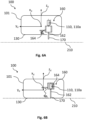
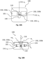
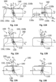
- Figs. 2A to 9B are various embodiments of a user-borne device 100 according to aspects of the present disclosure.
- the magnetic object 110 is transitioned from the first state to the second state in different ways, more specifically by providing different arrangements of the at least one contact manipulation feature 170 relative to the housing 101 and/or to the magnetic object 110.
- the at least one contact manipulation feature 170 may be arranged rotatable and/or translatable with respect to the housing 101.
- the at least one contact manipulation feature 170 may be in a default location.
- the default location of the at least one contact manipulation feature 170 is shown, e.g., in Fig. 2A .
- the at least one manipulation feature 170 may be at least partially arranged within the housing 101.
- a predominant part of the at least one manipulation feature 170 may be arranged within the housing 101.
- At least a portion of the at least one manipulation feature 170 may be arranged outside the housing 101, e.g., protruding out of the housing 101 by a protruding distance l and/or beyond an outer surface of the housing 101 as shown in Figs. 2A and 4A .
- the at least one contact manipulation feature 170 may be in a contact location.
- the contact location may be different from the default location as shown, e.g., in Fig. 2B . More specifically, each of the default location and the contact location may comprise a respective position and/or orientation of the at least one contact manipulation feature 170 relative to the housing 101.
- An actuation of the at least one contact manipulation feature 170 may cause a movement of the at least one contact manipulation feature 170 from the default location to the contact location.
- the at least one contact manipulation feature 170 may protrude further out (and beyond the outer surface) of the housing 101 than in the contact location.
- the at least one contact manipulation feature 170 in the contact location, may be substantially flush with the outer surface of the housing 101.
- the at least one contact manipulation feature 170 and/or the device contact surface 130 may be distanced to the interaction surface 210.
- the first state may be indicative of the user-borne device 100 being distanced to the interaction surface 210.
- the second state the at least one contact manipulation feature 170 and/or the device contact surface 130 may be in contact with the interaction surface 210.
- the second state may be indicative of the user-borne device 100 being in contact with the interaction surface 210.
- the at least one contact manipulation feature 170 and/or device contact surface or point 130 may be distanced to the interaction surface 210.
- the at least one contact manipulation feature 170 and/or device contact surface or point 130 may be in contact with the interaction surface 210.
- the housing 101 may comprise an outer surface. A portion of the outer surface may be a device contact surface 130.
- the housing 101 may comprise an opening 102 in the outer surface through which the at least one contact manipulation feature 170 may be movable. In the first state, the at least one manipulation feature 170 may at least partially protrude through the opening 102 and out of the housing 101.
- the opening 102 may be provided in the device contact surface 130. In embodiments, the opening 102 may be provided in a surface other than the device contact surface, e.g., a side surface or a top surface of the housing 101.
- the user-borne device 100 may comprise a click manipulation feature 150 and/or a scroll manipulation feature 140 (see, e.g., Fig. 1 ).
- the device contact surface 130 may be the surface, which may be in contact with the interaction surface 210 when the user-borne device 100 is operated on the interaction surface 210.
- the click and/or scroll manipulation features 140, 150 may be provided at outer surfaces of the user-borne device 100 not being the surface which is in contact with the interaction surface (i.e., the device contact surface 130). It should be noted that the user-borne device 100 could be accidentally placed upside down on the interaction surface 210 by a user.
- the device contact surface 130 may be the surface configured to provide the user-borne device 100 with the most stable and secure support possible on the interaction surface 210.
- the device contact surface 130 may be the surface which defines a plane that is substantially parallel to the interaction surface 210.
- the actuation of the at least one contact manipulation feature 170 may be provided by applying a force on the at least one contact manipulation feature 170.
- the at least one contact manipulation feature 170 may be actuatable by a user U, as shown in Figs. 3A and 3B .
- the transition may be caused based on an actuation of the at least one contact manipulation feature 170 by the user U.
- the at least one contact manipulation feature 170 may be arranged with respect to the housing 101 such that the at least one contact manipulation feature 170 may be accessible by a user in the default location and/or the contact location.
- the at least one contact manipulation feature 170 may be accessible at the device contact surface 130 or may be accessible at an outer surface of the housing 101 other than the device contact surface 130.
- the at least one manipulation feature 170 may comprise a button and/or a switch arranged on an outer surface of the housing 101, e.g., on a device contact surface 130, a side surface and/or a top surface of the housing 101).
- the at least one contact manipulation feature 170 i.e., at least the portion accessible by the user
- a force may be applied on the at least one contact manipulation feature 170 causing a transition of the magnetic object 110.
- the at least one manipulation feature 170 may be configured to rotate and/or translate into the housing 101. This may cause the transition of the magnetic object 110.
- the transition may indicate a contact event, which in turn may be detectable with the plurality of magnetometers 300.
- the at least one contact manipulation feature 170 may be arranged with respect to the housing 101 such that a contact of the housing 101 and/or at least one contact manipulation feature 170 with the interaction surface 210 may cause the actuation of the at least one contact manipulation feature 170, more specifically from the default location to the contact location.
- a force may be applied on the at least one contact manipulation feature 170. This in turn may cause a movement of the at least one contact manipulation feature 170 from the default location to the contact location.
- the at least one contact manipulation feature 170 may be rotated and/or translated into the housing 101, more specifically due to the contact with the interaction surface 210 applying a force on the at least one contact manipulation feature 170. It should be noted that a slight contact of the at least one contact manipulation feature 170 with the interaction surface or a slight actuation by a user may cause only a slight movement of the at least one contact manipulation feature 170. Due to the interaction with the magnetic object 110, the slight movement of the at least one contact manipulation feature 170 may only cause a slight transition of the magnetic object 110.
- the system 10 may set a threshold for a detected transition to ensure that a contact event is indeed present. Possible thresholds will be described in detail below.
- the housing 101 may comprise a flexible portion that may be elastically deformable when a force is applied on the flexible portion.
- the flexible portion may protrude from the outer surface of the housing 101 (i.e., protrude away from the housing 101).
- the flexible portion may be arranged on the device contact surface 130.
- the (more specifically entire) at least one contact manipulation feature 170 may be arranged within the housing.
- the flexible portion may be arranged with respect to the at least one contact manipulation feature 170 such that a force applied on the flexible portion from outside the housing 101 may cause an actuation of the at least one contact manipulation feature 170.
- the force applied to the flexible portion may be provided by a user pressing on the flexible portion or a contact of the housing 101 and/or flexible portion with the interaction surface 210 (e.g., by a physical contact with the interaction surface 210, or an actuation applied by a user on the flexible portion).
- gravitational forces acting on the user-borne device 100 i.e., based on its weight
- the physical contact with the interaction surface 210 may be sufficient to apply the force on the flexible portion.
- the at least one contact manipulation feature 170 may be in indirect contact with the interaction surface 210 and/or a user. In the default position, the flexible portion may protrude from the outer surface of the housing 101.
- the flexible portion In the contact location, the flexible portion may be deformed towards to the outer surface and may protrude less from the outer surface than in the default position.
- the movement of the flexible portion may be transmitted to the at least one contact manipulation feature 170 due to the physical contact between the flexible portion and the at least one contact manipulation feature 170.
- "Elastically deformable" means that the flexible portion may be able to regain its original shape in the default location (i.e., when no force is applied on the flexible portion).
- the flexible portion may be mechanically connected to the at least one contact manipulation feature 170.
- the user-borne device 100 may comprise a transmission device 160 operatively coupled to the at least one contact manipulation feature 170.
- Embodiments of the transmission device 160 are schematically illustrated in Figs. 1 to 9B .
- the transmission device 160 may be configured to interact with the magnetic object 110 such that the magnetic object 110 may be transitioned from the first state to the second state when the at least one manipulation feature 170 is actuated.
- the transmission device 160 may comprise at least one biasing mechanism 161.
- the biasing mechanism may be at least one first biasing mechanism.
- the biasing mechanism may be configured to urge the at least one contact manipulation feature 170 to the default location when the at least one manipulation feature 170 is not actuated.
- the at least one biasing mechanism may comprise a spring element.
- the at least one biasing mechanism may be provided as a weight coupled to the at least one contact manipulation feature 170 such that the at least one contact manipulation feature 170 may be urged to the default location due to gravitational forces acting on the weight. However, this may only be the case when the weight and/or the at least one contact manipulation feature 170 is oriented towards the device contact surface 130 being below the user-borne device 100.
- the magnetic object 110 or a magnetic field modification element 164 may be operatively coupled to the transmission device 160.
- the transmission device 160 may be configured to transmit a rotation and/or translation of the at least one contact manipulation feature 170 to the magnetic object 110 or to the modification element 164.
- a rotation and/or translation of the at least one manipulation feature 170 may cause a predefined rotation and/or translation of the magnetic object 110 or the modification element 164.
- the transmission device 160 may comprise a gear transmission 160a and/or a lever transmission 160b.
- the at least one biasing mechanism 161 as described above may be configured to urge the magnetic object 110 to the first location, when the at least one contact manipulation feature 170 is distanced to the interaction surface 110.
- the transmission device 160 may comprise at least one second biasing mechanism configured to urge the magnetic object 110 to the first location, when the at least one contact manipulation feature 170 is distanced to the interaction surface 110.
- the at least one biasing mechanism 161 or at least one third biasing mechanism may be configured to urge the modification element 164 to an exposed location or a covered location, which however, will be described in detail below.
- the lever transmission 160b may comprise at least one lever member 162 rotatable about at least one transmission rotation axis 118.
- the at least one lever member 162 may be rotatably coupled to the housing 101.
- the at least one lever member 162 may be coupled to the magnetic object 110 at a first end of the at least one lever member 162, and to the at least one contact manipulation feature 170 at a second end of the at least one lever member 162.
- the at least one lever member 162 may be fixedly or rotatably coupled to the magnetic object 110.
- the at least one lever member 162 may be rotatably and/or translatably coupled to the magnetic object 110.
- the at least one contact manipulation feature 170 may be fixedly or rotatably coupled to the lever member.
- the at least one lever member 162 may be rotatably and/or translatably coupled to the at least one contact manipulation feature 170.
- the transmission rotation axis 118 may be parallel to the first rotation axis 112 and/or the first device axis x d . In some embodiments the transmission rotation axis 118 may be parallel to the second device axis y d .
- the at least one biasing mechanism 161 as described above may be coupled to the at least one lever member 162 and to the housing 101. In the embodiment of Figs.
- the at least one lever member 162 may be fixedly coupled to the magnetic object 110 and rotatably coupled to the at least one contact manipulation feature 170.
- the at least one lever member 162 may comprise a first lever member 162a and at least one second lever member 162b operatively coupled to the first lever member 162a.
- the first lever member 162a may be fixedly or rotatably coupled to the magnetic object 110.
- the first lever member 162a may be rotatably and/or translatably coupled to the at least one second lever member 162b.
- the at least one second lever member 162b may be fixedly or rotatably coupled to the at least one contact manipulation feature 170.
- the transmission device 160 may comprise a gear transmission 160a comprising at least one gear wheel 163 via which the at least one contact manipulation feature 170 may be operatively coupled with the magnetic object 110 or the modification element 164.
- the at least one gear wheel 118 may be rotatable about the at least one transmission rotation axis 118.
- the at least one gear wheel 163 may be coupled to the magnetic object 110 such that a rotation of the at least one gear wheel 163 may cause a rotation and/or a translation of the magnetic object 110. As shown e.g., in Figs.
- the magnetic object 110 may be fixedly coupled the at least one gear wheel 163 such that a rotation of the at least one gear wheel 163 may cause a corresponding rotation of the magnetic object 110.
- the first rotation axis 112 or the second rotation axis 114 of the magnetic object 110 may be parallel to the at least one transmission rotation axis 118 or may be the same as the at least one transmission rotation axis 118.
- a rotation of the at least one gear wheel 163 may cause a rotation of the magnetic moment vector 120.
- the at least one transmission rotation axis 118 may be inclined or perpendicular to the magnetic moment vector 120.
- the transmission device 160 may comprise a lever transmission 160b and a gear transmission 160a as described above.
- the lever transmission 160a more specifically the at least one lever member 162, may comprise at least one actuation element 171 with one or more engagement features 172.
- the actuation element 171 may be coupled to the at least one contact manipulation feature 170, more specifically via the at least one lever member 162.
- the one or more engagement features 172 may be operatively coupled with the gear wheel 163 such that a translation (and/or rotation) of the at least one contact manipulation feature 170 and/or of the actuation element 171 may cause a rotation of the gear wheel 163.
- a translation (and/or rotation) of the at least one contact manipulation feature 170 and/or of the actuation element 171 may cause a rotation of the gear wheel 163.
- the transmission device 160 may be configured such that, when the at least one contact manipulation feature 170 is actuated, the at least one gear wheel 163 and/or the magnetic obj ect 110 may be rotated by a gear wheel rotation angle ⁇ from 10° to 360°, more specifically from 45° to 220°, and particularly from 90° to 180°.
- the at least one gear wheel 163 and the magnetic object 110 may be rotated by a gear wheel rotation angle ⁇ from 10° to 360°, more specifically from 45° to 220°, and particularly from 90° to 180°.
- an orientation of the magnetic object may transition from a first state to a second state (i.e., the transition may comprise a location change which will be described in detail below).
- the transition may be associated with a contact event of the user-borne device with the interaction surface. Due to the gear wheel rotation angle as defined above, such movement (i.e., the rotation) of the magnetic object 110 may be distinguished from other rotations of the magnetic object, e.g., due to normal user operations of the user-borne device (like tilting the user-borne device 100 in the air or on the interaction surface 210).
- the at least one gear wheel 163 may comprise a first orientation in the first state and a second orientation in the second state, wherein the at least one biasing mechanism 161 may be configured to urge the at least one gear wheel 163 to the first orientation when the at least one contact manipulation feature 170 is distanced to the interaction surface 210.
- the transmission device 160 may comprise the at least one gear wheel 163, the first lever member 162a, the at least one second lever member 162b, and the at least one actuation element 171.
- the at least one actuation element 171 may comprise a first actuation element 171a with first one or more engagement features 172a and at least one second actuation element 172b with second one or more engagement features 172b.
- the first lever member 162a may be coupled to the at least one contact manipulation feature 170 and may be operatively coupled to the at least one gear wheel 163 via the first actuation element 171a due to the engagement of the first one or more engagement features 172a with the gear wheel 163.
- additional lever members as described above may be provided between the at least one contact manipulation feature 170 and the at least one gear wheel 163.
- the at least one second lever member 162a may be operatively coupled to the at least one gear wheel 163 via the second actuation element 172a due to the engagement of the second one or more engagement features 172b with the gear wheel 163.
- the at least one gear wheel 163 may operatively couple the first lever member 162a with the at least one second lever member 162b.
- the at least one second lever member 162b may be coupled, more specifically fixedly coupled, with the modification element 164.
- Figs. 7A and 7B the at least one second lever member 162b may be coupled, more specifically fixedly coupled, with the modification element 164.
- the at least one second lever member 162b may be coupled, more specifically fixedly coupled, with the magnetic object 110.
- the at least one contact manipulation feature 170 may be operatively coupled to the magnetic object 110 or the modification element 164 such that an actuation of the at least one contact manipulation feature 170 may cause a translation of the magnetic object 110 or the modification element 164, more specifically towards the interaction surface 210, particularly towards the device contact surface or point 130.
- the at least one contact manipulation feature 170 may be operatively coupled to the magnetic object 110 or the modification element 164 such that an actuation of the at least one contact manipulation feature 170 may cause a rotation of the magnetic object 110 or the modification element 164.
- Figs. 1 to 9B illustrate various embodiments of a user-borne device 100 according to aspects of the present disclosure.
- the magnetic object 110 may be transitioned from the first state to the second state in various ways. In the following, possible transitions of the magnetic object 110 will be described in more detail.
- the magnetic object 110 may be configured to create a magnetic field.
- the transition of the magnetic object 110 from the first state to the second state may be detectable based on magnetic field measurements with a plurality of magnetometers 300.
- the transition of the magnetic object 110 may comprise a location change and/or a magnetic field change.
- the respective embodiments of the location change and/or magnetic field change will be explained in detail with reference to Figs. 2A to 9B below.
- the user-borne device 100 may be configured to control a contact event detectable with a plurality of magnetometers 300 based on the transition caused by an actuation of the at least one contact manipulation feature 170.
- the transition may comprise a location change of the magnetic object 110 relative to the housing 101.
- the magnetic object 110 may be movably coupled to the housing 101. More specifically, the magnetic object 110 may be arranged rotatable and/or translatable with respect to the housing 101.
- the magnetic object 110 may be arranged within the housing 101.
- the at least one contact manipulation feature 170 may be mechanically coupled to the magnetic object 110, more specifically via the transmission device 160.
- the location change may comprise a movement of the magnetic object 110 relative to the housing 101.
- the location change may be predetermined and/or limited by the geometric (or mechanical) design and associated conditions of the housing 101.
- the location change may be known or expected because it may be limited by the specific geometry and mechanical conditions of the housing 101 which may not be misinterpreted by the system as another interaction. More specifically, the movement may comprise a rotation and/or translation of the magnetic object 110 relative to the housing 101.
- the location change of the magnetic object 110 may comprise a movement of the magnetic object 110 from a first location to a second location relative to the housing 101.
- the at least one contact manipulation feature 170 may be mechanically coupled to the magnetic object 110 via the transmission device 160 such that an actuation of the at least one contact manipulation feature 170 may cause a translation and/or rotation of the magnetic object 110 from the first location to the second location.
- the actuation of the at least one contact manipulation feature 170 may cause the location change of the magnetic object 110.
- the location of the magnetic object 110 may comprise a position and/or an orientation of the magnetic object 110 relative to the housing 101.
- the position and/or orientation of the magnetic object 110 relative to the housing 101 may change when the at least one contact manipulation feature 170 is actuated.
- the magnetic object 110 In the first state, the magnetic object 110 may be at the first location (see, e.g., Fig. 2A ) and in the second state, the magnetic object 110 may be at the second location (see, e.g., Fig. 2B ), more specifically wherein the second location may be different from the first location.
- the location change from the first location to the second location may be defined by the movement, more specifically the rotation and/or translation of the magnetic object 110.
- the first location and the second location may each comprise a respective position and/or orientation of the magnetic object 110 relative to the housing 101.
- the location change and/or movement of the magnetic object 110 may be indicative of the contact event. More specifically, the location change and/or movement may be detectable based on magnetic field measurements associated with the magnetic object 110 with the plurality of magnetometers 300.
- the contact event may be determined based on the detected location change. More specifically, the system 10 may be configured to determine the contact event based on the detected transition, more specifically based on the detected location change and/or movement.
- the movement of the magnetic object 110 relative to the housing 101 may be a predefined movement.
- the predefined movement may comprise a predefined translation and/or rotation of the magnetic object 110 relative to the housing 101.
- the predefined movement may be indicative of the contact event and may be detectable with the plurality of magnetometers 300.
- the movement may comprise a movement trajectory, a movement velocity range, and/or a movement time range.
- the movement may be associated with a movement trajectory (e.g., a predefined movement trajectory) which can be provided by the rotation and/or translation of the magnetic object, more specifically from the first location to the second location.
- An actuation of the at least one contact manipulation feature may lead to a specific movement trajectory, movement velocity range and/or movement time range.
- the movement of the magnetic object 110 may be predefined.
- the movement trajectory, movement velocity range and/or movement time range may be linked with a contact event, e.g., when the at least one contact manipulation feature 170 contacts the interaction surface 210 or is actuated by a user.
- a contact event may be determined.
- the movement trajectory may be defined by a combination of a rotation and a translation of the magnetic object 110 relative to the housing 101. The combined translation and rotation may define the movement trajectory during transition and may be indicative of the contact event.
- the movement trajectory may be associated with a first direction, indicating a "contact on” event (i.e., wherein the user-borne device 100, more specifically the at least one contact manipulation feature 170, may be in contact with the interaction surface 210).
- the movement trajectory may be associated with a second direction opposite the first direction, indicating a "contact off' event (i.e., wherein the user-borne device 100, more specifically the at least one contact manipulation feature 170, may be distanced the interaction surface 210).
- the movement of the magnetic object e.g., the movement trajectory, may be limited by mechanical constraints and/or the shape of the housing 101 within which the magnetic object 110 may be arranged.
- the magnetic object 110 may be arranged within the housing 101 such that the movement, e.g., the movement trajectory, of the magnetic object 110 due to the actuation of the at least one contact manipulation feature 170 may be clearly distinguished, e.g., from a movement of the magnetic object caused by an actuation of a click manipulation feature 150 and/or a scroll manipulation feature 140 which will be described in detail below.
- a distance between the first location and the second location may be at least 2 mm.
- the movement time range may be at least 2ms.
- the magnetic object 110 may be translated and/or rotated towards a device contact surface 130. More specifically, the magnetic object 110 may be rotated about the at least one transmission rotation axis 118 and translated towards the device contact surface 130 from the first location to the second location when the at least one contact manipulation feature 170 is actuated. In this case, in the second location, the magnetic object 110 is closer to the interaction surface 210 than in the first location.
- the plurality of magnetometers may be arranged below the interaction surface 210 and a strength of the magnetic field created by the magnetic object 110 may be seen stronger in the second location than in the first location - which may be indicative of the contact event.
- the magnetic object 110 may define a magnetic moment vector 120 which may be associated with the magnetic field created by the magnetic object 110.
- a first angle ⁇ 1 may be defined between the magnetic moment vector 120 and the vertical device axis z d .
- a second angle ⁇ 2 may be defined between the magnetic moment vector 120 and the vertical device axis z d .
- the second angle ⁇ 2 may be larger than the first angle ⁇ 1 .
- a force applied on the at least one contact manipulation feature 170 may be transmitted to the transmission device 160, which in turn may rotate and/or translate the magnetic object 110 from the first location to the second location.
- the vertical device axis z d may be orthogonal to the device contact surface 130.
- the orientation of the magnetic object i.e., defined by the first angle ⁇ 1 and the second angle ⁇ 2
- the magnetic moment vector 120 in the first location, may be substantially perpendicular to the vertical device axis z d .
- the magnetic moment vector 120 in the second state, in the magnetic moment vector 120 may be substantially parallel to the vertical device axis z d .
- a first distance zi may be defined between a center of the magnetic object 110 and the device contact surface 130.
- a second distance z 2 may be defined between the center of the magnetic object 110 and the device contact surface 130.
- the second distance z 2 may be smaller than the first distance zi.
- the center may be a geometric center. The center may be known due to the mechanical arrangement of the magnetic object 110 within the housing 101 and/or due to the shape of the magnetic object 110. In some embodiments, the center of the magnetic object 110 may be the barycenter of the magnetic object 110. The center of the magnetic object 110 may be determined based on magnetic field measurements with the plurality of magnetometers. As shown in Figs.
- the first distance zi and the second distance z 2 may be measured parallel to the vertical device axis z d .
- the magnetic object 110 in the second state the magnetic object 110 may be closer to the interaction surface 210 due to the rotation and/or translation of the magnetic object 110 towards the device contact surface 130.
- a position of the least one magnetic object 110 may change within the housing 101.
- the magnetic object 110 may be configured to create or generate a magnetic field 115.
- the transition may comprise a magnetic field change of the magnetic object 110 detectable based on magnetic field measurements with the plurality of magnetometers 300.
- the magnetic field change may be detectable outside the user-borne device 100, more specifically the housing 101, with the plurality of magnetometers 300. Outside the user-borne device 100, more specifically the housing 101, means an environment of the user-borne device 100.
- the magnetic field change is detectable at least at one location (e.g.
- the magnetic field change of the magnetic object 110 may be indicative of the contact event.
- the contact event may be determinable on the basis of the detected magnetic field change, more specifically outside the housing 101.
- the magnetic properties of the magnetic object 110 may not change due to the transition. However, during transition, the resulting magnetic field seen and measured by the magnetometers may change.
- the magnetic field change may also be described with a magnetic object signature the magnetic object 110 may have in the first state and the second state, and which may change during transition.
- the magnetic signature of a magnetic object 110 may have distinctive characteristics making it possible to distinguish the magnetic object 110 from other magnetic objects, as well as to distinguish a first magnetic signature in the first state of the magnetic object 110 and a second magnetic signature in the second state of the magnetic object 110.
- the first and second magnetic signatures as well as the magnetic signature transition may be detectable outside the housing 101 with the plurality of magnetometers 300.
- Each magnetic signature may comprise a set of vectors describing a magnetic object vector field of the magnetic object 110 in the first and second states.
- the magnetic field 115 may comprise a magnetic field strength and/or a magnetic field form.
- the transition may comprise a change of the magnetic field strength and/or a change of the magnetic field form.
- the magnetic object 110 may comprise the magnetic object moment vector 120 and/or a magnetic object position vector associated with the magnetic field 115.
- the magnetic object 110 may be modeled as a magnetic dipole being defined by the magnetic object moment vector 120 and/or the magnetic object position vector.
- the magnetic object moment vector 120 and/or the magnetic object position vector may be used to determine the magnetic field change.
- the magnetic object moment vector 120 may define a magnetic object orientation and/or a magnetic object strength, i.e., the magnetic field strength of the magnetic object 110.
- the magnetic object strength may be related to the magnetization of the magnetic object 110 and its volume.
- the magnetic field form may be indicative of a 3D form of the magnetic field associated with the magnetic object 110.
- the change of the magnetic field strength and/or a change of the magnetic field form may occur due to another object being brought in proximity to (or away from) the magnetic object 110.
- the other object may have an influence (i.e., change) the magnetic field strength and/or the magnetic field form of the magnetic object 110.
- the magnetic field form may be defined by the magnetic object signature and the magnetic object vector field as described above, and which is detectable with the plurality of magnetometers. During transition (i.e., the magnetic field change), the magnetic object vector field may change which may be detectable, more specifically outside the housing 101, with the plurality of magnetometers 300.
- the magnetic object 110 in the first state may comprise a first magnetic field.
- the magnetic object 110 in the second state, may comprise a second magnetic field.
- the second magnetic field may be different from the first magnetic field.
- the first magnetic field may be the magnetic field 115 in the first state, and the second magnetic field may be the magnetic field 115 in the second state.
- the first magnetic field may be the magnetic field 115 at a first point of time t1.
- the second magnetic field may be the (same) magnetic field 115 at a second point of time t2, wherein t2>t1.
- the first magnetic field measured with the plurality of magnetometers at t1 may be different from the second magnetic field measured with the plurality of magnetometers at t2>t1.
- the magnetic object in the first state the magnetic object may have a first magnetic object vector field detectable with the plurality of magnetometers and in the second state the magnetic object may have a second magnetic object vector field detectable with the plurality of magnetometers.
- the transition may comprise a magnetic field change of the magnetic object 110 from the first magnetic field to the second magnetic field.
- the first magnetic field may comprise a first magnetic field strength and/or a first magnetic field form.
- the second magnetic field may comprise a second magnetic field strength and/or a second magnetic field form.
- the second magnetic field strength may be larger or smaller than the first magnetic field strength and/or the second magnetic field form may be different from the first magnetic field form (i.e., the magnetic object vector fields may be different).
- the transition comprising a magnetic field change may be provided in several ways. Some embodiments will be described with reference to Figs. 5A to 7D , 9A and 9B .
- the user-borne device 100 may comprise a magnetic field modification element 164 configured to magnetically interact with the magnetic object 110, more specifically with the magnetic field created by the magnetic object 110.
- Magnetically interact means that the magnetic field modification element 164 may affect (or have an impact on) the magnetic field 115 created by the magnetic object 110, more specifically depending on a location of the magnetic field modification element 164 relative to the magnetic object 110.
- the magnetic field modification element 164 may affect the magnetic object vector field (and its directions) measured with the plurality of magnetometers.
- the modification element 164 may be configured to change the magnetic field created by the magnetic object 110 depending on a location of the modification element 164 relative to the magnetic object 110.
- one of the magnetic object 110 and the modification element 164 may be operatively coupled to the at least one contact manipulation feature 170 and configured to change its location with respect to the respective other one of the magnetic object 110 and the modification element 164, when the at least one manipulation feature 170 is actuated.
- the magnetic object 110 may be movable relative to the modification element 164.
- At least one of the magnetic object 110 and the modification element 164 may be movable relative to the housing 101.
- each of the magnetic object 110 and the modification element 164 may be movable relative to the housing 101.
- Each of the modification element 164 and the magnetic object 110 may be arranged within the housing 101.
- the modification element 164 may be fixedly coupled to the housing 101 and the magnetic object 110 may be movably coupled to the housing 101.
- the magnetic object 110 may be operationally coupled to the at least one contact manipulation device 170.
- the magnetic object 110 may be mechanically coupled with the at least one contact manipulation feature 170, more specifically via the transmission device 160.
- the transmission device 160 may be fixedly coupled with the magnetic object 110 and/or the at least one contact manipulation feature 170.
- the modification element 164 may be movably coupled to the housing 101 and the magnetic object 110 may be fixedly coupled to the housing 101.
- the modification element 164 may be operationally coupled to the at least one contact manipulation device 170.
- the modification element 164 may be mechanically coupled with the at least one contact manipulation feature 170, more specifically via the transmission device 160.
- the transmission device 160 may be fixedly coupled with the modification element 164 and/or the at least one contact manipulation feature 170.
- the modification element 164 and the magnetic object 110 may be movably coupled to the housing 101.
- the modification element 164 may be operationally coupled to the at least one contact manipulation device 170.
- the modification element 164 may be mechanically coupled with the at least one contact manipulation feature 170, more specifically via the transmission device 160 as described above.
- the modification element 164 may be configured to enhance or attenuate the magnetic field created by the magnetic object 110.
- the modification element 164 may be configured to create (or generate) an additional magnetic field detectable outside the user-borne device 100, more specifically the housing 101, with the plurality of magnetometers 300, which will be described in more detail below.
- the modification element 164 may comprise a magnetic material.
- the magnetic material may be a paramagnetic material, a diamagnetic material, or a ferromagnetic material.
- the ferromagnetic material can be magnetized by an external magnetic field. When the ferromagnetic material is placed in a magnetic field, areas of the ferromagnetic material may align themselves with this magnetic field.
- the magnetization process may locally disturb the magnetic flux density of the magnetic field 115 created by the magnetic object 110.
- the ferromagnetic material of the modification element 164 may become itself a magnet and may disturb locally the magnetic field 115 created by the magnetic object 110.
- the magnetic field 115 applied to the ferromagnetic material may lead to a magnetization of the ferromagnetic material. However, this may only happen in case the magnetic field is strong enough, i.e., when the magnetic object 110 creating the magnetic field and the ferromagnetic material are brought in proximity with respect to each other. When the magnetic object 110 generating the magnetic field and the ferromagnetic material are moved away from each other, the ferromagnetic material can return to a neutral magnetic state.
- the diamagnetic material may be weakly magnetized in a direction opposite the direction of the magnetic field induced, i.e., the magnetic field 115 created by the magnetic object 110.
- the diamagnetic material may locally attenuate the magnetic field 115 created by the magnetic object 110 when brought in proximity to the magnetic object 110, which may be detected based on magnetic field measurements with the plurality of magnetometers 300.
- the paramagnetic material may be weakly magnetized in the direction of the magnetic field induced, i.e., the magnetic field 115 created by the magnetic object 110.
- the paramagnetic material may locally enhance the magnetic field 115 created by the magnetic object 110 when brought in proximity to the magnetic object 110, which may be detected based on magnetic field measurements with the plurality of magnetometers 300.
- the modification element 164 may comprise a shielding element configured to at least partially shield the magnetic field of the magnetic object 110 with respect to an environment outside of the housing 101, more specifically depending on the location of the shielding element relative to the magnetic object 110.
- the shielding element may be used to modify the magnetic field strength and/or magnetic field form of the magnetic object.
- the magnetic field strength of the magnetic field created by the magnetic object 110 may be attenuated or enhanced.
- an intensity of the magnetic field of the magnetic object 110 as detected by the plurality of magnetometers 300 may be attenuated or enhanced.
- the magnetic field may be deformed, e.g., such that the magnetic field may be no longer symmetric.
- the shielding element 164 may be a sleeve configured to at least partially receive the magnetic object 110.
- the sleeve may be configured to at least partially cover the magnetic object 110.
- the magnetic object 110 in the first state, may be in a covered location, wherein the magnetic object 110 is at least partially covered by the shielding element 164 with respect to the environment of the housing 101.
- the magnetic object 110 In the second state as shown in Figs. 5B and 7B , the magnetic object 110 may be in an exposed location, wherein the magnetic object 110 is exposed with respect to the environment of the housing 101.
- the magnetic object 110 in the second state the magnetic object 110 may be (fully) exposed to the environment of the housing 101 and/or not covered by the shielding element 164.
- “Covered” means that the magnetic object 110 may be at least partially encircled by the shielding element 164 and/or the shielding element may shield a surface of the magnetic object with respect to the environment.
- the covered location may be the first location and the exposed location may be the second location.
- at least a predominant portion of the magnetic object 110 along its length and/or its circumference may be encircled or shielded by the shielding element.
- the at least one contact manipulation feature 170 may be coupled to one of the magnetic object 110 and the shielding element 164 via the transmission device 160 such that an actuation of the at least one contact manipulation feature 170 may cause a translation and/or rotation of the magnetic object 110 from the covered location to the exposed location.
- the magnetic object 110 may be configured to create the first magnetic field in the covered location.
- the magnetic object 110 may be configured to create the second magnetic field in the exposed location.
- the magnetic object 110 may be in the covered location when the at least one contact manipulation feature 170 is distanced to the interaction surface 210.
- the magnetic object 110 may be in the exposed location, when the at least one contact manipulation feature 170 and/or device contact surface 130 is in contact with the interaction surface 210.
- the at least one contact manipulation feature 170 may be actuated by a user instead of being actuated by contacting the interaction surface 210.
- the transmission device 160 may comprise the at least one biasing mechanism 161, which may be configured to urge the magnetic object 110 and/or the shielding element 164 to the covered location, when the at least one manipulation feature 170 is distanced to the interaction surface 110 or not actuated by a user U.
- the above features may also apply - however, the covered location and exposed location may be the other way around with respect to the first state and the second state.
- the magnetic object 110 In the first state, the magnetic object 110 may be in an exposed location, wherein the magnetic object 110 may be exposed with respect to the environment of the housing 101.
- the magnetic object 110 In the second state as shown in Figs. 6B and 7D , the magnetic object 110 may be in a covered location, wherein the magnetic object 110 may be at least partially covered by the shielding element 164 with respect to the environment of the housing 101.
- the magnetic object 110 in the first state the magnetic object 110 may be (fully) exposed to the environment of the housing 101 and/or not covered by the shielding element 164.
- the at least one contact manipulation feature 170 may be coupled to one of the magnetic object 110 and the shielding element 164 via the transmission device 160 such that an actuation of the at least one contact manipulation feature 170 may cause a translation and/or rotation of the magnetic object 110 from the exposed location to the covered location.
- the magnetic object 110 may be in the exposed location when the at least one contact manipulation feature 170 is distanced to the interaction surface 210.
- the magnetic object 110 may be in the covered location, when the at least one contact manipulation feature 170 and/or device contact surface 130 is in contact with the interaction surface 210.
- the transmission device 160 may comprise at least one biasing mechanism 161, which may be configured to urge the magnetic object 110 and/or the shielding element 164 to the exposed location, when the at least one manipulation feature 170 is distanced to the interaction surface 110 or not actuated by a user U.
- the first magnetic field form may be substantially symmetric, more specifically rotationally symmetric.
- the second magnetic field form may be asymmetric.
- the transition may comprise both a location change and a magnetic field change, e.g., as indicated in Figs. 2A, 2B , 3A, 3B , 5A, 5B , 8A, 8B , 9A and 9B .
- the user-borne device 100 may be a writing device, more specifically a stylus or a pen.
- the housing 101 may be substantially cylindrical and may comprise a housing tip.
- the housing tip may comprise a nib configured to be operated on the interaction surface 210.
- the nib may protrude through the opening 102 provided in the housing tip and may be movable relative to the housing 101.
- the nib may be the at least one contact manipulation feature 170 or may be coupled to the at least one contact manipulation feature 170 such that an actuation (e.g., a translation) of the nib may cause an actuation (e.g., a translation and/or rotation) of the at least one contact manipulation feature 170.
- the at least one contact manipulation feature 170 may be coupled with the magnetic object 110 via the transmission device 160 as described above.
- the nib may define the device contact surface or point 130.
- An actuation of the nib may cause a translation of the magnetic object 110 towards the interaction surface 210, more specifically towards the device contact surface or point 130.
- the nib In the first state (i.e., in the default location), the nib may protrude out of the housing 101, more specifically through the opening 102, by a first protruding distance l1.
- the nib In the second state (i.e., in the contact location), the nib may protrude out of the housing 101, more specifically through the opening 102, by a second protruding distance l2, which may be smaller than the first protruding distance l1.
- the nib may move from the default location to the contact location. Due to the actuation of the nib, the magnetic object 110 may be moved from the first location to the second location, as indicated by the arrows in Fig. 9B .
- the transition may comprise the location change of the magnetic object 110.
- the location change may be detectable with the plurality of magnetometers 300 and may be indicative of the contact event.
- the modification element 164 may be provided and fixedly coupled to the nib (i.e., the at least one contact manipulation feature 170 as shown in Figs. 9A and 9B ).
- the transition may comprise a location change and a magnetic field change, which may lead to increased accuracy and reliability for detecting and determining the contact event.
- the at least one biasing mechanism 161 may be coupled to the first lever member 161 and the housing 101, and may be configured to urge the nib to the default location when the nib is distanced to the interaction surface 210.
- the transition from the first state to the second state may be indicative of a pressure event of the user-borne device 100.
- the pressure event may be indicative of a pressure applied to the at least one contact manipulation feature 170.
- the pressure event may be determined and/or analyzed based on the detected transition. In examples, the transition can be used to determine the magnitude of the pressure (e.g., over time) applied on the at least one contact manipulation feature 170.
- the pressure event may cause an action and/or may be used to control an action in the digital environment, more specifically the virtual environment.
- the pressure event may implement a user input or a physical contact of the at least one contact manipulation feature 170 with the interaction surface 210.
- the pressure event may be related to the movement of the magnetic object 110 as described above.
- the pressure event may be determined based on the pressure applied on the nib (i.e., based on the contact of the nib with the interaction surface 210).
- the user-borne device 100 may comprise at least one scroll manipulation feature 140 and/or at least one click manipulation feature 150, 150a, 150b. It should be noted that the below embodiments are explained with respect to the magnetic object 110. However, additional magnetic objects may be provided and the least one scroll manipulation feature 140 and/or at least one click manipulation feature 150 may be additionally or alternatively coupled to the additional magnetic objects.
- the at least one click manipulation feature 150 and/or the at least one scroll manipulation feature 140 may be movably coupled to the housing 101 and actuatable by a user U.
- the at least one scroll manipulation feature 140 and/or at least one click manipulation feature 150 may be translatable and/or rotatable with respect to the housing 101.
- the magnetic object 110 may be coupled to the at least one scroll manipulation feature 140 and/or at least one click manipulation feature 150. More specifically, the magnetic object 110 may be operationally, e.g., mechanically, coupled to at least one scroll manipulation feature 140 and/or at least one click manipulation feature 150.
- a translation and/or rotation of the at least one scroll manipulation feature 140 and/or at least one click manipulation feature 150 relative to the housing 101 may cause a translation and/or a rotation of the magnetic object 110 relative to the housing 101.
- the at least one scroll manipulation feature 140 and/or at least one click manipulation feature 150 may be actuated by a user U. In an initial state of the user-borne device 100, the at least one scroll manipulation feature 140 and/or at least one click manipulation feature 150 and/or the magnetic object 110 may be in an initial location. In an actuated state of the user-borne device 100, the at least one scroll manipulation feature 140 and/or at least one click manipulation feature 150 and/or the magnetic object 110 may be in the actuated location.
- the user-borne device 100 may be in the initial state. In case the at least one scroll manipulation feature 140 and/or at least one click manipulation feature 150 is actuated by user U, the user-borne device 100 may be in the actuated state. More specifically, in the actuated state, the at least one scroll manipulation feature 140 and/or at least one click manipulation feature 150 and/or the magnetic object 110 may be in the actuated location, more specifically wherein (or when) the at least one scroll manipulation feature 140 and/or at least one click manipulation feature 150 are actuated by a user U. An actuation of the at least one click manipulation feature 150 and/or at least one scroll manipulation feature 140 may cause a rotation and/or translation of the magnetic object 110 with respect to the housing 101 from the initial location to the actuated location.
- an actuation of the at least one scroll manipulation feature 140 and/or at least one click manipulation feature 150 may lead to a first rotation 180 about the second device axis y d as described above.
- a first rotation angle ⁇ 1 may have a positive value or a negative value.
- an actuation of the at least one scroll manipulation feature 140 and/or at least one click manipulation feature 150 may lead to the second rotation 190 about the first device axis x d as described above.
- a second rotation angle ⁇ 2 may have a positive value or a negative value.
- an actuation of the at least one scroll manipulation feature 140 and/or at least one click manipulation feature 150 may lead to a translation 160 of the magnetic object 110 along the first device axis x d , the second device axis y d , and/or the vertical device axis z d .
- an orientation of the magnetic object 110 relative to the housing 101 may be defined based on a set of inclination angles ⁇ 1 , ⁇ 2 , ⁇ 3 .
- the set of inclination angles ⁇ 1 , ⁇ 2 , ⁇ 3 may be measured between the magnetic moment vector 120 and the respective axes of the device coordinate system.
- ⁇ 1 may be measured between the vertical device axis z d and the magnetic moment vector 120.
- the magnetic moment vector 120 may be inclined by inclination angle ⁇ 1 with respect to the vertical device axis z d .
- the at least one biasing mechanism 161 as described above may be at least one first biasing mechanism.
- the user-borne device 100 may comprise at least one third biasing mechanism 155.
- the at least one first biasing mechanism and the at least one third biasing mechanism 155 may be the same biasing mechanism.
- the at least one third biasing mechanism 155 may be configured to urge the at least one scroll manipulation feature 140 and/or at least one click manipulation feature 150 and/or magnetic object 110 from the actuated location to the initial location, more specifically when the at least one scroll manipulation feature 140 and/or at least one click manipulation feature 150 is not actuated.
- the at least one scroll manipulation feature 140 and/or at least one click manipulation feature 150 when a user actuates (e.g., applies a force on) the at least one scroll manipulation feature 140 and/or at least one click manipulation feature 150, the at least one scroll manipulation feature 140 and/or at least one click manipulation feature 150 and magnetic object 110 may be moved from the initial location to the actuated location. In this case, the at least one third biasing mechanism 155 may be biased.
- the at least one scroll manipulation feature 140 and/or at least one click manipulation feature 150 and the magnetic object 110 may be urged from the actuated location to the initial location.
- the at least one scroll manipulation feature 140 and/or at least one click manipulation feature 150 may be associated with at least one interaction trigger event.
- the system 10 and/or the electronics device 500 may be configured to determine the respective interaction trigger event based on a translation and/or rotation of the magnetic object 110 relative to the user-borne device 100 as described above, more specifically caused by a translation and/or rotation of the least one scroll manipulation feature 140 and/or at least one click manipulation feature 150 being operationally coupled to the magnetic object 110.
- an electronics device 500 and/or the system 10 may be configured to determine a position and/or rotation deviation between the initial location and the actuated location.
- a specific translation and/or rotation of the magnetic object 110 relative to the at least one user-borne device 100 may be detectable by the system 10, more specifically by the electronics device 500. Based on the detected specific translation and/or rotation, the system 10 and/or the electronics device 500 may be configured to transform this movement to at least one trigger event associated with the translation and/or rotation.
- the system 10 and/or the electronics device 500 may be coupled to (and/or include) a database.
- the database may comprise data associating at least one interaction trigger event with a specific translation and/or rotation of the magnetic object 110 from the initial location to the actuated location.
- the system 10 and/or the electronics device 500 may be configured to transmit to and/or receive data from the database. In the embodiments shown in Figs.
- the first rotation 180 may be associated with a first trigger event.
- the second rotation 190 may be associated with a second trigger event.
- the respective trigger event may be, e.g., a click event, a scroll event, a keyboard event (e.g., in case the user-borne device 100 may be or comprise a keyboard) and/or a selection event.
- additional trigger events may be determined based on a rotation and/or translation of the magnetic objects relative to each other and detectable by the system 10 and/or the electronics device 500.
- the at least one interaction trigger event may be initiated by a user manipulation of the at least one user-borne device 100, more specifically the at least one electrically and/or electronically passive user-borne device 100, within the sensing volume M.
- the at least one interaction trigger event may cause an action and/or may be used to control an action in a digital environment (i.e., an environment which is controlled by a computer or a network of computers), e.g., a virtual environment, based on a user input. More specifically, the at least one interaction trigger event may implement a user input on the at least one user-borne device 100 as an action in the digital environment.
- the at least one user-borne device 100 may be used together with the electronics device 500 which may be or may comprise e.g., a tablet, a cell phone, a smartphone, a laptop, a computer, a virtual reality (VR) set, a notebook, a foldable smartphone, a foldable tablet, an electronics device sleeve and/or a television.
- the at least one interaction trigger event may cause an action on the electronics device 500 and/or may be used to control an action on the electronics device 500 based on a user input on the at least one user-borne device 100.
- a scroll event may trigger a scroll action including scrolling of files or data, a rotational or translational movement of the virtual object associated with a selection of a choice from a plurality of choices.
- the scroll action may also include rotating a body in a virtual environment and/or changing a perspective in a virtual environment.
- a scroll action may include one or more of moving a cursor in two opposing directions (e.g., horizontal or vertical on an output device), moving a displayed element (e.g. a page, a cursor), which may be controlled by the at least one user-borne device 100, a step in a direction, flipping through a menu, flipping through a selection list, or adjusting (e.g. increasing or decreasing) a parameter (e.g.
- a click event may trigger a click action (more specifically of a virtual object) in a digital environment, more specifically a virtual environment, based on a user input.
- a click event may include, e.g., a selection of an object (like a button, a file, an icon or another object), a selection of an item, a selection of a list, a selection of an item on a list.
- a click event may trigger a following action.
- a click event may trigger an action that provides additional information and/or properties of an object, an item or a text (e.g., letter, word, phrase) selected.
- a click event may trigger a single click action, a double click action, a triple click action, a right click action and/or a click-and-drag action within a digital environment, more specifically a virtual environment.
- a single click action may refer to selection of an object within a virtual environment.
- a double click action may open a file or execute a program within a virtual environment.
- a click-and-drag action may include clicking, holding and moving an object, e.g., which may be used to highlight or drag-select a text or an object.
- a triple click action may be used to select a paragraph of a text.
- a right click action may perform a special action, e.g., opening a list with additional information and/or properties for a selected object as mentioned above.
- the action that is triggered by the click event depends on the user's input on the at least one user-borne device 100.
- the click event may cause a double-click action when a user provides two quick and successive inputs on the at least one user-borne device 100.
- the above-mentioned features enable various new application fields for the at least one user-borne device 100, for example a computer-mouse, a stylus, a keyboard, a dial, a mouse scroll element (e.g., a wheel), a joystick, a control for an electronic device (e.g. an audio control or a visual control), a control of software settings or visualizations (e.g. graphic software or design software), or a control of a computer game.
- the user-borne device 100 may comprise a first click manipulation feature 150a, at least one second click manipulation feature 150b and at least one scroll manipulation feature 140.
- Each of the first click manipulation feature 150a, the at least one second click manipulation feature 150b and the at least one scroll manipulation feature 140 may be operationally coupled to the magnetic object 110 or may be coupled to additional, different magnetic objects.
- the user-borne device 100 may be, e.g., a computer mouse. Actuating the first click manipulation feature 150a or the at least one second click manipulation feature 150b may lead to the first rotation 180 of the magnetic object 110.
- the first rotation angle ⁇ 1 may comprise a positive value or a negative value.
- the system 10 and/or the electronics device 500 may be configured to detect the first rotation angle ⁇ 1 and may transform this rotation into a click event comprising a first click event or a second click event, depending on the first rotation angle value.
- the first click event may trigger a left click action more specifically a single click action, a double click action, a triple click action, and/or a click-and-drag action as described above.
- the second click event may trigger the right click action as described above. Actuating the at least one scroll manipulation feature 140 may lead to the second rotation 190 of the magnetic object 110.
- the second rotation angle ⁇ 2 may comprise a positive value or a negative value.
- the system 10 and/or the electronics device 500 may be configured to detect the second rotation angle ⁇ 2 and may transform this rotation into a scroll event.
- the scroll event may comprise a first scroll event or a second scroll event.
- the respective scroll event may depend on the second rotation angle value.
- the first rotation 180 may be associated with a click event. In case the first rotation angle ⁇ 1 has a positive value, this may be associated with a first click event. In case the first rotation angle ⁇ 1 has a negative value, this may be associated with a second click event.
- the second rotation 190 may be associated with a scroll event.
- the second rotation angle ⁇ 2 has a positive value, this may be associated with a first scroll event (e.g.. a "scroll up"). In case the second rotation angle ⁇ 2 has a negative value, this may be associated with a second scroll event (e.g., a "scroll down").
- the at least one click manipulation feature 150, the at least one scroll manipulation feature 140 and/or the at least one contact manipulation feature 170 may be configured to interact with the magnetic object 110 such that an actuation of the at least one click manipulation feature 150, the at least one scroll manipulation feature 140 and/or the at least one contact manipulation feature 170 cause the transition of the magnetic object 110 from the first state to the second state.
- the magnetic object 110 may be operatively coupled to the at least one click manipulation feature 150 and/or to the at least one scroll manipulation feature 140 such that an actuation of the at least one click manipulation feature 150 and/or at least one scroll manipulation feature 140 may cause a rotation and/or translation of the magnetic object 110 with respect to the housing 101.
- the magnetic object 110 may be transitioned from the first state to the second state.
- the transition may comprise the features as described above for the at least one contact manipulation feature 170.
- the at least one click manipulation feature 150 and/or to the at least one scroll manipulation feature 140 and the at least one contact manipulation feature 170 may be coupled to the magnetic object 110 (more specifically, to the same magnetic object 110).
- the user-borne device 100 may be configured to control at least one trigger event based on the rotation and/or translation of the magnetic object 110 caused by an actuation of the at least one click manipulation feature 150 and/or at least one scroll manipulation feature 140.
- the user-borne device 100 may be configured to control a contact event detectable with a plurality of magnetometers 300 based on the transition caused by the actuation of the at least one contact manipulation feature 170, more specifically wherein the trigger event may be detectable only in response to a detected contact event.
- the magnetic object 110 may be a first magnetic object 110a and the user-borne device 100 may comprise at least one second magnetic object 110b.
- the first magnetic object 110a and the at least one second magnetic object 110b may be arranged distanced to each other.
- the distance between the first magnetic object 110a and the at least one second magnetic object 110b may be large enough such that the plurality of magnetometers 300 may identify them as two separate magnetic objects.
- the at least one second magnetic object 110b may comprise the features as described above for the magnetic object 110.
- the at least one second magnetic object 110b may be arranged within the housing 101.
- the at least one contact manipulation feature 170 may be mechanically coupled to the first magnetic object 110a via the transmission device 160 such that an actuation of the at least one contact manipulation feature 170 may cause a translation and/or rotation of the first magnetic object 110a from the first location to the second location.
- the first magnetic object 110a may be translated towards or away from and/or rotated relative to the at least one second magnetic object 110b.
- the at least one second magnetic object 110b may be arranged translatable and/or rotatable with respect to the housing 101, or, the at least one second magnetic object 110b may be fixedly coupled to the housing 101.
- the first magnetic object 110a may be operatively coupled to the at least one contact manipulation feature 170.
- the at least one second magnetic object 110b may be operatively coupled to the at least one click manipulation feature 150 and/or to the at least one scroll manipulation feature 140 such that an actuation of the at least one click manipulation feature 150 and/or at least one scroll manipulation feature 140 may cause a rotation and/or translation of the at least one second magnetic object 110b with respect to the housing 101, more specifically wherein the at least one second magnetic object 110b is in an actuated state.
- the at least one second magnetic object 110b may be arranged translatable and/or rotatable with respect to the housing 101.
- the user-borne device 100 may comprise a first magnetic object 110a operatively coupled with the at least one contact manipulation feature 170, a second magnetic object operatively coupled with the at least one click manipulation feature 150, and at least one third magnetic object operatively coupled with the at least one scroll manipulation feature 140.
- the user-borne device 100 may comprise at least one fourth magnetic object fixedly coupled to the housing. The at least one fourth magnetic object may be used for improved location determination.
- one magnetic object per contact manipulation feature, scroll manipulation feature and click manipulation feature may be provided.
- the first magnetic object 110a may comprise a first magnetic moment vector 120a and/or a first magnetic object position vector
- the at least one second magnetic object 110b may comprise a second magnetic moment vector 120b and/or a second magnetic object position vector.
- the first magnetic object 110a and the at least one second magnetic object 110b may be arranged within the housing, such that the first magnetic object 110a and the at least one second magnetic object 110b may rotate relative to each other based on an actuation of the at least one contact manipulation feature 170, the at least one scroll manipulation feature 140 and/or the at least one click manipulation feature 150.
- the rotation of the first magnetic object 110a and the at least one second magnetic object 110b relative to each other may be detectable based on magnetic field measurements with the plurality of magnetometers 300. More specifically, the orientation of the first magnetic moment vector 120a and the at least one second magnetic moment vector 120b relative to each other may be determined. Based on the rotation of the first magnetic moment vector 120a relative to the at least one second magnetic moment vector 120b, the contact event and/or the trigger event may be determined.
- the first magnetic object 110a and the at least one second magnetic object 110b are arranged in the housing 101, such that, in the first state (i.e., the contact manipulation feature is not actuated) and the initial state (i.e., the at least one scroll manipulation feature 140 and/or the at least one click manipulation feature 150 are not actuated), the first magnetic moment vector 120a may be substantially parallel to the second magnetic moment vector 120b.
- the first magnetic object 110a in the first state and the initial state, the first magnetic object 110a may be arranged in the housing 101, such that the first magnetic moment vector 120a may be substantially parallel to the vertical device axis z d .
- the first magnetic moment vector 120a and/or the second magnetic moment vector 120b may be oriented such that a rotation of the first magnetic object 110a and/or the second magnetic object 110b about a first rotation axis 112 and at least one second rotation axis 114 may be detectable based on magnetic field measurements with a plurality of magnetometers 300.
- the user-borne device 100 as described above may comprise a tactile and/or audible feedback device (not shown in the Figs.).
- the tactile and/or audible feedback device may be configured to provide a tactile and/or audible feedback to a user U based on a control of a contact event and/or at least one trigger event. More specifically, the tactile and/or audible feedback device may provide a tactile and/or audible feedback to a user U based on an actuation of the at least on contact manipulation feature 170, the at least one click manipulation feature 150 and/or the at least one scroll manipulation feature 140.
- Fig. 1 schematically illustrates a system 10 for determining a manipulation of a user-borne device 100 according to a second aspect of the present disclosure.
- the manipulation of the user-borne device 100 may be provided by a contact, more specifically a physical contact of the user-borne device with the interaction surface, or by a user U.
- the system 10 comprises a user-borne device 100 according to the first aspect of the present disclosure.
- the user-borne device 10 may comprise any of the above-described embodiments and/or features.
- the 10 system comprises a plurality of magnetometers 300.
- the plurality of magnetometers 300 is configured to measure the magnetic field created or generated by the magnetic object 110.
- the system is configured to detect a transition of the magnetic object 110 from a first state to a second state.
- the system 10 is configured to determine a contact event of the user-borne device 100 with the interaction surface 210 based on the detected transition. The transition from the first state to the second state, the contact event and the associated features are already explained above.
- the system 10 may allow the tracking and/or location determination of a user-borne device 100, more specifically an electronically and/or electrically user-borne device 100, in at least five degrees of freedom.
- the plurality of magnetometers 300 may be configured to create a sensing volume M (as indicated, e.g., in Fig. 1 ).
- the sensing volume may have an ellipsoidal form.
- the plurality of magnetometers 300 may be associated with a magnetometer plane 310. More specifically, the magnetometer plane 310 may be defined by a plane that may extend through a majority of the plurality of magnetometers 300.
- the user-borne device 100 may be operable on the interaction surface 210, more specifically wherein the interaction surface 210 may be defined within the sensing volume M.
- the system 10 may comprise a reference coordinate system XYZ, which may be defined relative to the plurality of magnetometers 300.
- the reference coordinate system XYZ may comprise a first reference axis X, a second reference axis Y and a vertical reference axis Z.
- the first reference axis X and the second reference axis Y may be orthogonal with respect to each other.
- the vertical reference axis Z may be orthogonal to the first reference axis X and the second reference axis Y.
- the vertical reference axis Z may extend through a center of the plurality of magnetometers 300.
- the first reference axis X and the second reference axis Y may be defined on the magnetometer plane 310.
- the vertical reference axis Z may be orthogonal to the magnetometer plane 310.
- the plurality of magnetometers 300 may be configured to measure the magnetic field 115 generated or created by the magnetic object 110.
- Each magnetometer of the plurality of magnetometers 300 may be configured to measure the magnetic field created by the magnetic object 110 in the direction of the first reference axis X, the second reference axis Y, and/or the vertical reference axis Z.
- each magnetometer of the plurality of magnetometers 300 may be configured to perform magnetic field measurements in the direction of one axis (i.e., one dimension), two axes (i.e., two dimensions), or three axes (i.e., three dimensions).
- the number of magnetometers provided may depend on the size of the interaction surface 210, on which the user-borne device 100 is operated, or, on the desired size of the sensing volume M within which the user-borne device 100 is operated.
- the plurality of magnetometers 300 may be configured to collect magnetic field measurements associated with the magnetic object 110 within the sensing volume M up to a maximum measurement distance, wherein the maximum measurement distance may be a distance within which the magnetic field measurements can be provided with acceptable reliability and/or accuracy. In embodiments, the maximum measurement distance may be 18cm, more specifically 15cm.
- the magnetic object 110 and the interaction surface 210 may within the maximum measurement distance.
- the minimum magnet field generated by a magnetic object 110 that may be tracked with the system may comprise at least 1 micro tesla.
- the plurality of magnetometers 300 may be fixedly arranged in a magnetometer body 320 (see, e.g., Fig. 9A ) defining a fixed position and/or orientation of the plurality of magnetometers 300 with respect to each other.
- the magnetometer plane 310 may be defined by a plane that extends through a majority of the plurality of magnetometers 300. More specifically, the magnetometer plane 310 may extend through centers, more specifically geometric centers, of a majority of the plurality of magnetometers 300. In other words, most of the magnetometers of the plurality of magnetometers 300 may be arranged in a common plane, i.e., the magnetometer plane 310.
- one or more magnetometers of the plurality of magnetometers 300 may be distanced and/or inclined with respect to the common plane, e.g., due to manufacturing issues and/or tolerances.
- the magnetometer plane 310 may additionally or alternatively be defined by a plane in which the magnetometers of the plurality of magnetometers 300 are predominantly arranged.
- the plurality of magnetometers 300 may be arranged in rows and columns. However, it is also possible that the plurality of magnetometers may be arranged in an unordered manner within the magnetometer body 320. A calibration procedure may be used to determine the exact locations, measurement axes, sensitivity and/or offset of each magnetometer within the magnetometer body 320 relative to the reference coordinate system XYZ.
- the plurality of magnetometers 300 are shown in Fig. 14 as being arranged in the magnetometer plane 310 (i.e., in the same plane relative to the vertical reference axis Z). However, as outlined above, one or more of the magnetometers may be distanced to the magnetometer plane 310, more specifically distanced in the direction of the vertical reference axis Z.
- the plurality of magnetometers 300 may be arranged in the magnetometer body 320 in rows k und columns l.
- Fig. 14 illustrates some magnetometers S k,l of the plurality of magnetometers 300.
- Each magnetometer S k,l may comprise a vertical magnetometer axis z M which may be arranged on the intersections of the rows k and columns l.
- Adjacent magnetometers S k,l , S k,l+1 , S k,l-1 may be separated along a row k by a distance d l,l+1 and d l,l-1 .
- Adjacent magnetometers S k,l , S k+1,l , S k-1,l may be separated along a column l by a distance d k,k+1 and d k,k-1 . As outlined above, the distances d k , d l between the respective magnetometers S k,l may be equal or may differ.
- the system 10 may further comprise or be connectable to a processing unit 400.
- the system 10, more specifically the processing unit 400 may be configured to track a movement of the magnetic object 110 and/or the user-borne device 100 in at least five degrees of freedom.
- the at least five degrees of freedom may include a translation of the magnetic object 110 along the first reference axis X, the second reference axis Y and the vertical reference axis Z, a rotation about the first rotation axis 112 and a rotation about the second rotation axis 114.
- a rotation about the third rotation axis 116 may be additionally detected.
- the system 10 may be configured to track a movement of the magnetic object 110 and/or the user-borne device 100 in at least six degrees of freedom.
- the system 10 may be configured to determine the contact event between the user-borne device 100 and the interaction surface 210 based on the detected transition.
- the system 10 detects the contact event, it may derive the location of the interaction surface 210 with high accuracy and reliability.
- the location determination and/or tracking of the user-borne device 100 may be done relative to the interaction surface 210. This may be done based on a determined user-borne device location and the interaction surface location as described in the method below.
- the system 10 may be configured to track a movement of the user-borne device 100 within the sensing volume M and/or relative to the interaction surface 210 over a time period. More specifically the system 10 may be configured to determine a trajectory of the user-borne device 100 within the sensing volume M and/or relative to the interaction surface 210. In embodiments, the user-borne device 100 may be tracked over a time period comprising multiple time samples. At each time sample, the location of the user-borne device 100 within the sensing volume M and/or relative to the interaction surface 210 may be determined. The system 10, more specifically the processing unit 400 may be configured to detect the transition and to determine the contact event based on the detected transition.
- the user-borne device 100 may be operable on the interaction surface 210 and the system 10 may be configured to determine a location of the user-borne device 100 within the sensing volume relative to the interaction surface 210 based on the magnetic field measurements. More specifically, the system may be configured to determine a movement of the user-borne device 100 on the interaction surface 210 based on the determined contact event and the determined location of the user-borne device 100.
- the system 10, more specifically the processing unit 400, may be configured to determine the at least one trigger event as described above.
- the at least one trigger event may be determined based on a control of the user-borne device 100 (e.g., a manipulation of the user-borne device by a user).
- the user-borne device 100 may comprise the at least one click manipulation feature 150 and/or the at least one scroll manipulation feature 140 as described above, which may be movably coupled to the housing 101 and actuatable by a user U.
- the at least one click manipulation feature 150, the at least one scroll manipulation feature 140 and/or the at least one contact manipulation feature 170 may be configured to interact with the magnetic object 110 such that an actuation of the at least one click manipulation feature 150, the at least one scroll manipulation feature 140 and/or the at least one contact manipulation feature 170 may cause the transition of the magnetic object 110 from the first state to the second state as described above.
- the magnetic object 110 may be operatively coupled to the at least one click manipulation feature 150 and/or to the at least one scroll manipulation feature 140 such that an actuation of the at least one click manipulation feature 150 and/or at least one scroll manipulation feature 140 may cause a rotation and/or translation of the magnetic object 110 with respect to the housing 101.
- the system 10 may be configured to determine the at least one trigger event based on the detected transition from the first state to the second state, or, based on a detected rotation and/or translation of the magnetic object 110 caused by an actuation of the at least one click manipulation feature 150 and/or at least one scroll manipulation feature 140. The same may apply to the embodiments, wherein a plurality of magnetic objects 110a, 110b are provided.
- the system 10 may be configured to determine the at least one trigger event only in response to a detected contact event. In other words, the at least one trigger event may not be determined as long as a contact event is not detected.
- the system 10 may be configured to determine the scroll event and/or the click event based on determining an actuation of the at least one scroll manipulation feature 140 and/or at least one click manipulation feature 150 by a user U, more specifically wherein the magnetic object 110 may be rotated about the first rotation axis 112 and the second rotation axis 114 (and additionally the third rotation axis 116 in case the magnetic object 110 is configured to create an asymmetric magnetic field).
- the system 10 may comprise at least one output device 510.
- the at least one output device 510 may be configured to represent the user-borne device 100. More specifically, the at least one output device 510 may be configured to visually reproduce the user-borne device 100 as a virtual object.
- the system 10 may comprise one output device 510.
- the output device 510 may be a visual screen or display.
- the system 10 may be configured to reproduce a movement of the user-borne device 100 within the sensing volume M and/or on the interaction surface 210 as a movement of the virtual object on the at least one output device 510.
- the system 10 may be configured to visually reproduce the at least one trigger event on the output device 510.
- the system 10 may be configured to represent, more specifically to visually reproduce, a determined contact event on the output device 510.
- the magnetic field 115 created by the magnetic object 110 may comprise a magnetic field strength.
- the system 10 may be configured to set a threshold for the magnetic field strength, and the system 10 may be configured to reject magnetic field measurements associated with a magnetic field strength that is equal to or less than the set threshold for the magnetic field strength.
- the magnetic field 115 may be defined by the magnetic field strength, a magnetic field location and/or a magnetic field direction. These parameters may be derived from the magnetometer measurements.
- magnetic field measurements with a magnetic field strength equal to or smaller than a threshold magnetic field strength may be rejected.
- the magnetic field strength may increase to a value being larger than the set magnetic field strength threshold. In this case, the system 10 may accept the magnetic field measurements. This may lead to increased accuracy and reliability for determining a contact event and/or the location of the user-borne device 100 relative to the interaction surface 210.
- the system 10 may comprise an electronics device 500 as mentioned above.
- the at least one output device 510 may be integrated in the electronics device 500.
- the electronics device 500 may be a tablet, a cell phone, a laptop, a computer, a virtual reality (VR) set or a television.
- the processing unit 400 may be integrated in the electronics device 500.
- the electronics device 500 may comprise a user interface configured to interact with a user U and/or receive a user input.
- the user interface may be integrated into the at least one output device 510.
- the plurality of magnetometers 300 may be configured to receive data from and/or transmit data to the processing unit 400.
- the system 10 may comprise a data storage connected to the processing unit 400.
- the data storage may comprise a primary data storage, e.g., a RAM, and a secondary data storage.
- the data storage may be integrated in and/or connected to the electronics device 500.
- the system 10 may comprise an interaction support 200 having an interaction support surface 230.
- the interaction surface 210 may be at least a partial surface of the interaction support surface 230.
- the interaction support 200 may not comprise ferromagnetic properties, e.g., ferromagnetic particles.
- the interaction support 200 may be a furniture (e.g., a table), a notebook, an electronics device 500, a screen, a wall, or a mouse pad.
- the interaction surface 210 may be defined based on a first set of geometric parameters associated with the interaction support 200. More specifically, the type of interaction support 200 may be known, e.g., a notebook or mouse pad. Such an interaction support 200 may be defined by a set of predefined geometric parameters.
- a partial surface of the interaction support surface 230 may be used as interaction surface 210.
- the system 10 may be configured to determine and/or to track the user-borne device 100 relative to the interaction surface 210. This requires the definition of an interaction surface location and the user-borne device 100 may be operated on different interaction surfaces which may not be known by the system 10. This may be done based on a determined user-borne device location and the interaction surface location as described in the method below.
- the system 10 may determine a contact event, this may indicate that the user-borne device 100 may be in physical contact with the interaction surface 210.
- the system 10 may derive a plane of the interaction surface 210, e.g., due to the device contact surface 130 being in contact with the interaction surface 210.
- the system 10 may determine multiple contact events from which the system 10 may derive multiple device contact points on the interaction surface 210.
- the system 10 may be configured to prompt a user U via the user interface to actuate the at least one contact manipulation feature 170 at multiple surface locations of the interaction surface 210 which are distanced to each other.
- the multiple surface locations may be stored and the system may derive a set of geometric parameters describing the interaction surface 210 with high accuracy and reliability. Based on the magnetic field measurements of the magnetic object 110 from which the magnetic object location may be determined relative to the device coordinate system and/or to the interaction surface 210.
- the plurality of magnetometers 300 may be electrically (e.g., via wires or a data bus) or wirelessly connected to the processing unit 400, an external processing unit and/or to the electronics device 500.
- the plurality of magnetometers 300 may be integrated in a wall, a furniture, a notebook, an electronics device 500, a screen, a keyboard, and/or a mouse pad.
- the interaction surface 210 may be a screen or display placed in front of the plurality of magnetometers 300.
- the interaction surface 210 may be defined on the at least one output device 510.
- the user-borne device 100 is configured to control at least one trigger event. More specifically, the at least one trigger event may cause an action and/or may be used to control an action in a digital environment, more specifically a virtual environment, based on a user input.
- the system 10 may determine the contact event, which may also cause an action and/or may be used to control an action in the digital (or virtual) environment.
- the user-borne device 100 according to the above aspects of the present disclosure may be reproduced as a virtual object in the virtual environment.
- the electronics device 500 may be a VR set, more specifically an XR headset which may be a device worn on a user's head and configured to allow a user to experience virtual environments in real life (virtual reality environment, or VR environment).
- the user-borne device 100 may be reproduced as a virtual object in the VR environment allowing a user U to recognize where the user-borne device 100 is located.
- a plurality of magnetometers 300 may be provided creating a sensing volume M in which the user-borne device 100 is operated.
- the user-borne device location (see, e.g., as described above and/or with respect to the method below) may be indicative of an orientation and/or a position of the user borne device 100 relative to the reference coordinate system XYZ, more specifically to the plurality of magnetometers 300.
- the reference coordinate system XYZ may be fixed in the VR environment.
- a position and/or an orientation of the user-borne device 100 may be computed relative to the VR set, more specifically to the XR headset, and may be reproduced, particularly displayed, to the user via the XR headset.
- the reference coordinate system XYZ may be dynamically evaluated from a tracking of the VR environment of the XR headset.
- the at least one trigger event e.g., the click event or scroll event
- the caused action may also be represented in the VR environment, more specifically which may be displayed to a user U via a display arranged in the XR headset.
- the representation in the VR environment may be done by changing a rendering parameter of the user-borne device 100, for instance color or light, and/or adding a specific sound.
- the interaction surface 210 may be modeled in the VR environment, displayed to a user via the XR headset and/or used as an input to represent an interaction between the user-borne device 100 and the interaction surface 210 within the VR environment (e.g., representing the user-borne device 100 being operated on the interaction surface 210 within the VR environment).
- the system 10 may be configured to detect the transition and to determine the contact event.
- the system 10 may adjust the location (including the position and/or orientation) of the interaction surface within the digital (or virtual) environment.
- a distance and/or orientation of the "virtual" interaction surface may thereby be adjusted relative to the XR headset worn by the user.
- a method 600 for determining a manipulation of a user-borne device 100 is provided.
- Methods for determining the location of a user-borne device with a plurality of magnetometers, and the manipulation of a user-borne device 100 within a sensing volume, associated algorithms are already known in the prior art, for example in US 2013/249784 A1 , US 2020/116524 A1 or US 2015/057969 A1 .
- the method 600 may comprise determining a user-borne device location within the sensing volume M created by the plurality of magnetometers 300 and based on the obtained magnetic field measurements.
- the method 600 may comprise defining the reference coordinate system XYZ as described above.
- Determining a user-borne device location may comprise determining an absolute magnetic object location indicative of an absolute magnetic object position and/or an absolute magnetic object orientation of the magnetic object 110 relative to the reference coordinate system XYZ. More specifically, the absolute magnetic object location may be determined based on the obtained magnetic field measurements.
- the absolute magnetic object location may comprise an absolute magnetic object position and/or an absolute magnetic object orientation relative to the reference coordinate system XYZ.
- the absolute magnetic object location may be determined based on an implementation of a mathematical model associating each measurement of a magnetometer of the plurality of magnetometers 300 with a location of the magnetic object 110 in the reference coordinate system XYZ.
- Each magnetometer of the plurality of magnetometers 300 may be a vector magnetometer and may be configured to measure the magnetic field in one, two or three dimensions.
- a coulombian model may be implemented, which may allow a modeling of complex magnetizations of the magnetic object 110.
- Determining a user-borne device location may further comprise determining a relative magnetic object location indicative of a relative magnetic object position and/or a relative magnetic object orientation of the magnetic object relative to the user-borne device 100, more specifically to a device coordinate system as described above.
- the set of geometric parameters may comprise predefined geometric parameters indicative of a geometric position and a geometric orientation of the magnetic object 100 relative to the user-borne device 100, more specifically relative to the housing 101 in the first state (i.e., the first location and initial location of the magnetic object)
- the user-borne device location may be known.
- the method 600 may further comprise applying a filter for filtering the determined user-borne device location. Magnetic and electronic noise, as well as environmental variations may lead to non-smooth location determinations over time. Based on the filtering, a smooth location trajectory of the user-borne device 100 relative to the reference coordinate system XYZ and/or to interaction surface 210 may be achieved.
- the filter may be a low-pass filter or a Kalman filter, more specifically an extended Kalman filter or an unscented Kalman filter.
- the method 600 may further comprise initializing the plurality of magnetometers 300 and the user-borne device 100, more specifically when a user U starts a user operation.
- the user-borne device 100 and/or the magnetic object 110 may be tracked over a time period comprising multiple time samples. At each time sample, the method 600 may comprise determining the user-borne device location. The method may further comprise storing the determined and/or detected features for each time sample.
- Fig. 16 schematically illustrates a process flow diagram of the method 600 according to the present disclosure.
- the method 600 comprises obtaining magnetic field measurements 610 associated with a magnetic field created by a magnetic object 110 coupled to a housing 101 of a user-borne device 100 according to the first aspect of the present disclosure and measured with a plurality of magnetometers 300.
- the method 600 may comprise obtaining measurements of a magnetic field created or generated by the magnetic object 110 and measured with the plurality of magnetometers 300.
- the method 600 comprises detecting a transition 620 of the magnetic object 110 from a first state to a second state and determining a contact event 630 of the user-borne device 100 with the interaction surface 210 based on the detected transition.
- the method 600 may comprise determining a pressure event of the user-borne device 600 based on the detected transition.
- detecting a transition 620 may comprise detecting a location change 621 and/or detecting a magnetic field change 622 of the magnetic object 110, more specifically outside the housing 101.
- the method 600 may comprise determining an interaction surface location, wherein the interaction surface location may be indicative of an interaction surface position, an interaction surface orientation and/or an interaction surface distance relative to the reference coordinate system XYZ, more specifically to the magnetometer plane 310. Determining the interaction surface location may be based on detecting the transition and determining the contact event as described above. Determining the interaction surface location may comprise deriving a geometric position and/or a geometric orientation of the interaction surface 210 relative to the reference coordinate system XYZ and the user-borne device 100 based on the determined contact event.
- the method 600 may comprise deriving a plane of the interaction surface 210 based on the determined contact event (which indicates that the device contact surface or point 130 lies on the interaction surface 210).
- the method 600 may determine multiple contact events from which the method 600 may derive multiple device contact points on the interaction surface 210.
- the method may comprise prompting a user U via the user interface to actuate the at least one contact manipulation feature 170 at multiple interaction surface locations of the interaction surface 210 which are distanced to each other.
- the multiple interaction surface locations may be stored and the method may comprise deriving a set of geometric parameters describing the interaction surface 210 with high accuracy and reliability.
- the method 600 may comprise determining the user-borne device location relative to the interaction surface 210 based on the interaction surface location.
- the method 600 may further comprise determining a contact location of the user-borne device 100 relative to the interaction surface 210, more specifically based on the determined user-borne device location and the determined interaction surface location. This can be provided with high accuracy and reliability since the interaction surface location and in turn the contact location can be derived from the determined contact event.
- Detecting a location change 621 may comprise detecting a movement of the magnetic object 110 relative to the housing 101 from a first location to a second location, more specifically wherein the movement may comprise a translation and/or rotation of the magnetic object 110.
- the movement may comprise a movement trajectory, a movement velocity range, and/or a movement time range.
- Determining a contact event 630 may comprise comparing the movement of the magnetic object 110 with a predefined movement.
- the method 600 may communicate with a data base storing predefined movements, e.g., including a predefined movement trajectory, a predefined movement velocity range, and/or a predefined movement time range.
- Determining a contact event 630 may comprise determining whether the movement of the magnetic object 110 matches the predefined movement, and in response to determining that the movement of the magnetic object 110 matches the predefined movement, determining the contact event 630 , wherein the contact event may be indicative that the user-borne device 100 is in contact with the interaction surface 210. Additionally or alternatively, determining a pressure event may comprise comparing the movement of the magnetic object 110 with the predefined movement.
- Determining a pressure event may comprise determining whether the movement of the magnetic object 110 matches the predefined movement, and in response to determining that the movement of the magnetic object 110 matches the predefined movement, determining the pressure event, wherein the pressure event may be indicative of an amount of pressure (e.g., over time) applied to the at least one contact manipulation feature 170.
- Detecting a magnetic field change 622 may comprise determining a change of the magnetic field created by the magnetic object 110 outside the user-borne device 100, more specifically outside the housing 101, from a first magnetic field in the first state to a second magnetic field in the second state, wherein the second magnetic field may be different from the first magnetic field.
- the first magnetic field of the magnetic object 110 may comprise a first magnetic field strength and/or a first magnetic field form in the first state
- determining a contact event 630 may comprise setting a threshold for the change of the magnetic field strength and/or the change of the magnetic field form. Furthermore, determining a contact event 630 may comprise rejecting magnetic field measurements associated with a change of the magnetic field strength and/or the change of the magnetic field form being equal to or less than the set threshold for the change of the magnetic field strength and/or the change of the magnetic field form, and/or accepting magnetic field measurements associated with a change of the magnetic field strength and/or the change of the magnetic field form being larger than the set threshold for the change of the magnetic field strength and/or the change of the magnetic field form.
- determining a contact event 630 may comprise, in response to detecting the change of the magnetic field strength and/or the change of the magnetic field form, determining the contact event, wherein the contact event may be indicative that the user-borne device 100 is in contact with the interaction surface 210.
- the method 600 may further comprise detecting a translation and/or rotation 640 of the magnetic object 110 about or relative to a first rotation axis 112 and at least one second rotation axis 114, 116 based on the obtained magnetic field measurements, and in response to a detected translation and/or rotation, determining at least one trigger event 650 based on the detected translation and/or rotation. In some embodiments, method 600 may further comprise determining the at least one trigger event only in response to detecting the contact event.
- determining at least one trigger event 650 may comprise determining a manipulation of the user-borne device 100, more specifically a control of the user-borne device 100, within the sensing volume M created by the plurality of magnetometers 300 based on the detected translation and/or rotation, and associating the manipulation with the at least one trigger event.
- Determining the at least one trigger event 650 may comprise determining a click event based on detecting a transition of the magnetic object 110, 110a from the first state to the second state or based on a detected translation and/or rotation of the at least one second magnetic object 110 relative to the housing 101 due to an actuation of the at least one click manipulation feature 150, and/or determining a scroll event based on detecting a transition of the magnetic object 110, 110a from the first state to the second state or based on a detected translation and/or rotation of the at least one second magnetic object 110 relative to the housing 101 due to an actuation of the at least one scroll manipulation feature 140.
- the method 600 may further comprise representing the user-borne device 100 and/or the magnetic object 110 on the output device 510. More specifically, representing the user-borne device 100 on an output device 510 may comprise reproducing the user-borne device 100 as a virtual object on the output device 510. Representing the user-borne device 100 may further comprise reproducing a movement of the user-borne device 100 and/or the magnetic object 110 within the sensing volume M and/or relative to the interaction surface 210 as a movement of the virtual object on the output device 510. The movement of the user-borne device 100 within the sensing volume M may be caused by a manipulation of the user-borne device 100 during a user operation (i.e., by a user manipulating the location of the user-borne device 100 and/or the magnetic object 110).
- the movement of the user-borne location may be determined and reproduced as a movement of the virtual object on the output device 510.
- the visual reproduction may be a motion of a cursor on the output device 510.
- the visual reproduction may not be identical to the design of the user-borne device 100 but may be any icon (e.g., an arrow, a picture).
- the method 600 as described above may be a computer-implemented method.
- a computer system may be configured to execute the computer-implemented method 600 as described above.
- a computer program may be configured to execute the computer-implemented method 600 as described above.
- a computer-readable medium or signal storing the computer program may be provided.
- the above-described computer-implemented method 600 can comprise or be executable via a computer or a network of computers, the computer or network of computers comprising at least one processing unit (e.g., a processor) and at least one data storage (i.e., memory).
- the described procedural logic may be held in the form of executable code in at least one data storage and executed by the at least one processing unit.
- the systems and subsystems may send data to the at least one processing unit and, in examples, they may also receive instructions from the at least one processing unit.
- the processing unit may thereby direct user-initiated and/or automatically generated queries to the system 10.
- the system 10 is not limited to a particular hardware environment. Thus, distributed devices coupled via a network may perform the techniques described herein.
- more than one user-borne devices 100 may be provided and operated (e.g., manipulated by a user U) within the sensing volume M created by the plurality of magnetometers 300.
- the method 600 and the system 10 according to the present disclosure have been described for one user-borne device 100, the features as described above may also be applicable to every additional or other user-borne device 100 operated within the sensing volume M.
Landscapes
- Engineering & Computer Science (AREA)
- Physics & Mathematics (AREA)
- General Physics & Mathematics (AREA)
- Life Sciences & Earth Sciences (AREA)
- Remote Sensing (AREA)
- General Engineering & Computer Science (AREA)
- Theoretical Computer Science (AREA)
- Electromagnetism (AREA)
- Condensed Matter Physics & Semiconductors (AREA)
- Environmental & Geological Engineering (AREA)
- Geology (AREA)
- General Life Sciences & Earth Sciences (AREA)
- Geophysics (AREA)
- Human Computer Interaction (AREA)
- Position Input By Displaying (AREA)
Priority Applications (3)
| Application Number | Priority Date | Filing Date | Title |
|---|---|---|---|
| EP23306333.8A EP4502772A1 (fr) | 2023-08-03 | 2023-08-03 | Accessoires passifs |
| CN202480054360.1A CN121729664A (zh) | 2023-08-03 | 2024-07-16 | 无源附件 |
| PCT/EP2024/070123 WO2025026726A1 (fr) | 2023-08-03 | 2024-07-16 | Accessoires passifs |
Applications Claiming Priority (1)
| Application Number | Priority Date | Filing Date | Title |
|---|---|---|---|
| EP23306333.8A EP4502772A1 (fr) | 2023-08-03 | 2023-08-03 | Accessoires passifs |
Publications (1)
| Publication Number | Publication Date |
|---|---|
| EP4502772A1 true EP4502772A1 (fr) | 2025-02-05 |
Family
ID=87575875
Family Applications (1)
| Application Number | Title | Priority Date | Filing Date |
|---|---|---|---|
| EP23306333.8A Pending EP4502772A1 (fr) | 2023-08-03 | 2023-08-03 | Accessoires passifs |
Country Status (3)
| Country | Link |
|---|---|
| EP (1) | EP4502772A1 (fr) |
| CN (1) | CN121729664A (fr) |
| WO (1) | WO2025026726A1 (fr) |
Citations (5)
| Publication number | Priority date | Publication date | Assignee | Title |
|---|---|---|---|---|
| US20130249784A1 (en) | 2012-03-22 | 2013-09-26 | Fredrik BR Gustafson | Method and Device for Pose Tracking Using Vector Magnetometers |
| US20150057969A1 (en) | 2012-03-29 | 2015-02-26 | Commissariat à I' énergie atomique et aux énergies alternatives | Method and device for locating a magnetic object |
| US20200116524A1 (en) | 2017-05-31 | 2020-04-16 | ISKn | Method for estimating the position of a magnet comprising a phase for identifying a magnetic disturbance |
| WO2022018691A1 (fr) * | 2020-07-22 | 2022-01-27 | Universita' Degli Studi Di Siena | Système de suivi d'un objet |
| US20220258039A1 (en) * | 2019-07-19 | 2022-08-18 | Advanced magnetic interaction (AMI) | Method for controlling a graphic interface for displaying the launching of a projectile in a virtual environment |
-
2023
- 2023-08-03 EP EP23306333.8A patent/EP4502772A1/fr active Pending
-
2024
- 2024-07-16 WO PCT/EP2024/070123 patent/WO2025026726A1/fr active Pending
- 2024-07-16 CN CN202480054360.1A patent/CN121729664A/zh active Pending
Patent Citations (5)
| Publication number | Priority date | Publication date | Assignee | Title |
|---|---|---|---|---|
| US20130249784A1 (en) | 2012-03-22 | 2013-09-26 | Fredrik BR Gustafson | Method and Device for Pose Tracking Using Vector Magnetometers |
| US20150057969A1 (en) | 2012-03-29 | 2015-02-26 | Commissariat à I' énergie atomique et aux énergies alternatives | Method and device for locating a magnetic object |
| US20200116524A1 (en) | 2017-05-31 | 2020-04-16 | ISKn | Method for estimating the position of a magnet comprising a phase for identifying a magnetic disturbance |
| US20220258039A1 (en) * | 2019-07-19 | 2022-08-18 | Advanced magnetic interaction (AMI) | Method for controlling a graphic interface for displaying the launching of a projectile in a virtual environment |
| WO2022018691A1 (fr) * | 2020-07-22 | 2022-01-27 | Universita' Degli Studi Di Siena | Système de suivi d'un objet |
Also Published As
| Publication number | Publication date |
|---|---|
| WO2025026726A1 (fr) | 2025-02-06 |
| CN121729664A (zh) | 2026-03-24 |
Similar Documents
| Publication | Publication Date | Title |
|---|---|---|
| US7283127B2 (en) | Stylus input device utilizing a permanent magnet | |
| JP5985645B2 (ja) | 磁気スタイラス | |
| JP6171016B2 (ja) | 磁場センサを用いて使用者入力を判断する電気装置 | |
| CN103124951B (zh) | 信息处理装置 | |
| US20100107099A1 (en) | Proximity interface apparatuses, systems, and methods | |
| US10990222B2 (en) | Calibration of trackpad | |
| Yoon et al. | Tring: Instant and customizable interactions with objects using an embedded magnet and a finger-worn device | |
| Yoon et al. | TMotion: Embedded 3D mobile input using magnetic sensing technique | |
| US20160139694A1 (en) | User input device using alternating current magnetic field and electric device having same | |
| WO2024132880A1 (fr) | Accessoires passifs | |
| KR100936046B1 (ko) | 촉각 센서를 이용한 마우스 기능을 갖는 터치패드 구현방법 | |
| US10474108B2 (en) | Magnetic sensor array for crown rotation | |
| EP4375815B1 (fr) | Représentation dépendante du mode d'un dispositif magnétique porté par l'utilisateur | |
| WO2025026726A1 (fr) | Accessoires passifs | |
| EP4375812B1 (fr) | Détection d'un emplacement d'un dispositif porté par l'utilisateur avec une pluralité de magnétomètres | |
| JPH04172521A (ja) | ポインティング制御装置 | |
| EP4375814B1 (fr) | Procédés et systèmes de commande de dispositifs à sorties multiples ou de localisation d'accessoires passifs dans de multiples espaces | |
| EP4375813A1 (fr) | Détection d'une rotation d'un aimant dans un dispositif porté par l'utilisateur avec une pluralité de magnétomètres | |
| KR20120016379A (ko) | 객체 제어 장치 및 방법 | |
| EP4375811A1 (fr) | Dispositif porté par l'utilisateur avec détection magnétique du contrôle de défilement | |
| EP4668079A1 (fr) | Dispositif, système et procédé de détection et/ou de détermination d'entrée | |
| EP4375816A1 (fr) | Événement de défilement contrôlé par détection magnétique de la rotation d'un appareil porté par l'utilisateur |
Legal Events
| Date | Code | Title | Description |
|---|---|---|---|
| PUAI | Public reference made under article 153(3) epc to a published international application that has entered the european phase |
Free format text: ORIGINAL CODE: 0009012 |
|
| STAA | Information on the status of an ep patent application or granted ep patent |
Free format text: STATUS: THE APPLICATION HAS BEEN PUBLISHED |
|
| AK | Designated contracting states |
Kind code of ref document: A1 Designated state(s): AL AT BE BG CH CY CZ DE DK EE ES FI FR GB GR HR HU IE IS IT LI LT LU LV MC ME MK MT NL NO PL PT RO RS SE SI SK SM TR |
|
| STAA | Information on the status of an ep patent application or granted ep patent |
Free format text: STATUS: REQUEST FOR EXAMINATION WAS MADE |
|
| 17P | Request for examination filed |
Effective date: 20250801 |
|
| GRAP | Despatch of communication of intention to grant a patent |
Free format text: ORIGINAL CODE: EPIDOSNIGR1 |
|
| STAA | Information on the status of an ep patent application or granted ep patent |
Free format text: STATUS: GRANT OF PATENT IS INTENDED |
|
| INTG | Intention to grant announced |
Effective date: 20260130 |