EP4502929A1 - Dispositif d'estimation de configuration de vis, procédé d'estimation de configuration de vis et programme informatique - Google Patents
Dispositif d'estimation de configuration de vis, procédé d'estimation de configuration de vis et programme informatique Download PDFInfo
- Publication number
- EP4502929A1 EP4502929A1 EP23778953.2A EP23778953A EP4502929A1 EP 4502929 A1 EP4502929 A1 EP 4502929A1 EP 23778953 A EP23778953 A EP 23778953A EP 4502929 A1 EP4502929 A1 EP 4502929A1
- Authority
- EP
- European Patent Office
- Prior art keywords
- screw
- pieces
- data
- construction
- appearance
- Prior art date
- Legal status (The legal status is an assumption and is not a legal conclusion. Google has not performed a legal analysis and makes no representation as to the accuracy of the status listed.)
- Pending
Links
Images


Classifications
-
- G—PHYSICS
- G01—MEASURING; TESTING
- G01N—INVESTIGATING OR ANALYSING MATERIALS BY DETERMINING THEIR CHEMICAL OR PHYSICAL PROPERTIES
- G01N21/00—Investigating or analysing materials by the use of optical means, i.e. using sub-millimetre waves, infrared, visible or ultraviolet light
- G01N21/84—Systems specially adapted for particular applications
- G01N21/88—Investigating the presence of flaws or contamination
- G01N21/8851—Scan or image signal processing specially adapted therefor, e.g. for scan signal adjustment, for detecting different kinds of defects, for compensating for structures, markings, edges
-
- G—PHYSICS
- G06—COMPUTING OR CALCULATING; COUNTING
- G06V—IMAGE OR VIDEO RECOGNITION OR UNDERSTANDING
- G06V20/00—Scenes; Scene-specific elements
- G06V20/60—Type of objects
-
- B—PERFORMING OPERATIONS; TRANSPORTING
- B29—WORKING OF PLASTICS; WORKING OF SUBSTANCES IN A PLASTIC STATE IN GENERAL
- B29C—SHAPING OR JOINING OF PLASTICS; SHAPING OF MATERIAL IN A PLASTIC STATE, NOT OTHERWISE PROVIDED FOR; AFTER-TREATMENT OF THE SHAPED PRODUCTS, e.g. REPAIRING
- B29C48/00—Extrusion moulding, i.e. expressing the moulding material through a die or nozzle which imparts the desired form; Apparatus therefor
- B29C48/25—Component parts, details or accessories; Auxiliary operations
- B29C48/256—Exchangeable extruder parts
- B29C48/2561—Mounting or handling of the screw
-
- B—PERFORMING OPERATIONS; TRANSPORTING
- B29—WORKING OF PLASTICS; WORKING OF SUBSTANCES IN A PLASTIC STATE IN GENERAL
- B29C—SHAPING OR JOINING OF PLASTICS; SHAPING OF MATERIAL IN A PLASTIC STATE, NOT OTHERWISE PROVIDED FOR; AFTER-TREATMENT OF THE SHAPED PRODUCTS, e.g. REPAIRING
- B29C48/00—Extrusion moulding, i.e. expressing the moulding material through a die or nozzle which imparts the desired form; Apparatus therefor
- B29C48/25—Component parts, details or accessories; Auxiliary operations
- B29C48/256—Exchangeable extruder parts
- B29C48/2564—Screw parts
-
- B—PERFORMING OPERATIONS; TRANSPORTING
- B29—WORKING OF PLASTICS; WORKING OF SUBSTANCES IN A PLASTIC STATE IN GENERAL
- B29C—SHAPING OR JOINING OF PLASTICS; SHAPING OF MATERIAL IN A PLASTIC STATE, NOT OTHERWISE PROVIDED FOR; AFTER-TREATMENT OF THE SHAPED PRODUCTS, e.g. REPAIRING
- B29C48/00—Extrusion moulding, i.e. expressing the moulding material through a die or nozzle which imparts the desired form; Apparatus therefor
- B29C48/25—Component parts, details or accessories; Auxiliary operations
- B29C48/36—Means for plasticising or homogenising the moulding material or forcing it through the nozzle or die
- B29C48/395—Means for plasticising or homogenising the moulding material or forcing it through the nozzle or die using screws surrounded by a cooperating barrel, e.g. single screw extruders
- B29C48/40—Means for plasticising or homogenising the moulding material or forcing it through the nozzle or die using screws surrounded by a cooperating barrel, e.g. single screw extruders using two or more parallel screws or at least two parallel non-intermeshing screws, e.g. twin screw extruders
-
- B—PERFORMING OPERATIONS; TRANSPORTING
- B29—WORKING OF PLASTICS; WORKING OF SUBSTANCES IN A PLASTIC STATE IN GENERAL
- B29C—SHAPING OR JOINING OF PLASTICS; SHAPING OF MATERIAL IN A PLASTIC STATE, NOT OTHERWISE PROVIDED FOR; AFTER-TREATMENT OF THE SHAPED PRODUCTS, e.g. REPAIRING
- B29C48/00—Extrusion moulding, i.e. expressing the moulding material through a die or nozzle which imparts the desired form; Apparatus therefor
- B29C48/25—Component parts, details or accessories; Auxiliary operations
- B29C48/36—Means for plasticising or homogenising the moulding material or forcing it through the nozzle or die
- B29C48/50—Details of extruders
- B29C48/505—Screws
-
- B—PERFORMING OPERATIONS; TRANSPORTING
- B29—WORKING OF PLASTICS; WORKING OF SUBSTANCES IN A PLASTIC STATE IN GENERAL
- B29C—SHAPING OR JOINING OF PLASTICS; SHAPING OF MATERIAL IN A PLASTIC STATE, NOT OTHERWISE PROVIDED FOR; AFTER-TREATMENT OF THE SHAPED PRODUCTS, e.g. REPAIRING
- B29C48/00—Extrusion moulding, i.e. expressing the moulding material through a die or nozzle which imparts the desired form; Apparatus therefor
- B29C48/25—Component parts, details or accessories; Auxiliary operations
- B29C48/92—Measuring, controlling or regulating
-
- G—PHYSICS
- G06—COMPUTING OR CALCULATING; COUNTING
- G06Q—INFORMATION AND COMMUNICATION TECHNOLOGY [ICT] SPECIALLY ADAPTED FOR ADMINISTRATIVE, COMMERCIAL, FINANCIAL, MANAGERIAL OR SUPERVISORY PURPOSES; SYSTEMS OR METHODS SPECIALLY ADAPTED FOR ADMINISTRATIVE, COMMERCIAL, FINANCIAL, MANAGERIAL OR SUPERVISORY PURPOSES, NOT OTHERWISE PROVIDED FOR
- G06Q10/00—Administration; Management
- G06Q10/04—Forecasting or optimisation specially adapted for administrative or management purposes, e.g. linear programming or "cutting stock problem"
-
- G—PHYSICS
- G06—COMPUTING OR CALCULATING; COUNTING
- G06Q—INFORMATION AND COMMUNICATION TECHNOLOGY [ICT] SPECIALLY ADAPTED FOR ADMINISTRATIVE, COMMERCIAL, FINANCIAL, MANAGERIAL OR SUPERVISORY PURPOSES; SYSTEMS OR METHODS SPECIALLY ADAPTED FOR ADMINISTRATIVE, COMMERCIAL, FINANCIAL, MANAGERIAL OR SUPERVISORY PURPOSES, NOT OTHERWISE PROVIDED FOR
- G06Q10/00—Administration; Management
- G06Q10/06—Resources, workflows, human or project management; Enterprise or organisation planning; Enterprise or organisation modelling
- G06Q10/063—Operations research, analysis or management
- G06Q10/0639—Performance analysis of employees; Performance analysis of enterprise or organisation operations
- G06Q10/06395—Quality analysis or management
-
- G—PHYSICS
- G06—COMPUTING OR CALCULATING; COUNTING
- G06Q—INFORMATION AND COMMUNICATION TECHNOLOGY [ICT] SPECIALLY ADAPTED FOR ADMINISTRATIVE, COMMERCIAL, FINANCIAL, MANAGERIAL OR SUPERVISORY PURPOSES; SYSTEMS OR METHODS SPECIALLY ADAPTED FOR ADMINISTRATIVE, COMMERCIAL, FINANCIAL, MANAGERIAL OR SUPERVISORY PURPOSES, NOT OTHERWISE PROVIDED FOR
- G06Q50/00—Information and communication technology [ICT] specially adapted for implementation of business processes of specific business sectors, e.g. utilities or tourism
- G06Q50/04—Manufacturing
-
- G—PHYSICS
- G06—COMPUTING OR CALCULATING; COUNTING
- G06T—IMAGE DATA PROCESSING OR GENERATION, IN GENERAL
- G06T7/00—Image analysis
- G06T7/0002—Inspection of images, e.g. flaw detection
- G06T7/0004—Industrial image inspection
- G06T7/0006—Industrial image inspection using a design-rule based approach
-
- G—PHYSICS
- G06—COMPUTING OR CALCULATING; COUNTING
- G06V—IMAGE OR VIDEO RECOGNITION OR UNDERSTANDING
- G06V10/00—Arrangements for image or video recognition or understanding
- G06V10/20—Image preprocessing
- G06V10/22—Image preprocessing by selection of a specific region containing or referencing a pattern; Locating or processing of specific regions to guide the detection or recognition
-
- G—PHYSICS
- G06—COMPUTING OR CALCULATING; COUNTING
- G06V—IMAGE OR VIDEO RECOGNITION OR UNDERSTANDING
- G06V10/00—Arrangements for image or video recognition or understanding
- G06V10/70—Arrangements for image or video recognition or understanding using pattern recognition or machine learning
- G06V10/764—Arrangements for image or video recognition or understanding using pattern recognition or machine learning using classification, e.g. of video objects
- G06V10/765—Arrangements for image or video recognition or understanding using pattern recognition or machine learning using classification, e.g. of video objects using rules for classification or partitioning the feature space
-
- G—PHYSICS
- G06—COMPUTING OR CALCULATING; COUNTING
- G06T—IMAGE DATA PROCESSING OR GENERATION, IN GENERAL
- G06T2207/00—Indexing scheme for image analysis or image enhancement
- G06T2207/30—Subject of image; Context of image processing
- G06T2207/30108—Industrial image inspection
Definitions
- the present disclosure relates to a screw construction inference device, a screw construction inference method and a computer program.
- screw pieces As for a screw of an extruder, multiple types of screw pieces are combined and integrated together. The screw pieces are checked for an assembly error with eyes. For a twin-screw extruder, the screw pieces are checked for an assembly error based on a feel when two screws are combined and rotated.
- Patent Literature 1 Japanese Patent Application Laid-Open Publication No. 2018-43419
- the object of the present disclosure is to provide a screw construction inference device, a screw construction inference method and a computer program that are capable of inferring the alignment positions and types of multiple screw pieces that constitute a screw for an extruder.
- a screw construction inference device is a screw construction inference device inferring a construction of a screw used for an extruder constructed by assembling a plurality of screw pieces, comprising: an acquisition unit that acquires appearance data indicating an appearance of the screw or the plurality of screw pieces aligned; and an arithmetic unit that infers an alignment position and a type for each of the plurality of screw pieces constituting the screw, based on the acquired appearance data.
- a screw construction inference method is a screw construction inference method inferring a construction of a screw used for an extruder constructed by assembling a plurality of screw pieces, comprising: acquiring appearance data indicating an appearance of the screw or the plurality of screw pieces aligned; and inferring an alignment position and a type for each of the plurality of screw pieces constituting the screw, based on the acquired appearance data.
- a computer program is a computer program causing a computer to execute processing of inferring a construction of a screw used for an extruder constructed by assembling a plurality of screw pieces, the computer program causing the computer to execute the processing of: acquiring appearance data indicating an appearance of the screw or the plurality of screw pieces aligned; and inferring an alignment position and a type for each of the plurality of screw pieces constituting the screw, based on the acquired appearance data.
- the alignment positions and types of multiple screw pieces that constitute a screw for an extruder can be inferred.
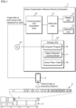
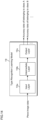
- FIG. 1 is a block diagram illustrating an example of the configuration of a screw construction inference device 1 according to Embodiment 1.
- the screw construction inference device 1 according to Embodiment 1 is a computer that executes arithmetic processing for inferring the construction of a screw 3 formed by assembling multiple screw pieces 3a for an extruder A.
- the extruder A includes a cylinder with a heater, the screw 3 that is provided so as to be drivable in a rotary direction within the cylinder and melts/plasticizes and kneads raw materials, and a rotary motor that rotates the screw 3.
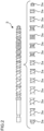
- FIG. 2 is a schematic diagram illustrating an example of the configuration of the screw 3.
- multiple types of screw pieces 3a are combined and integrated together to form a bar of screw 3.
- a flight screw-shaped forward flight piece that carries raw materials in a forward direction, a reverse flight piece that carries raw materials in a reverse direction, a kneading piece that kneads raw materials and the like are combined in an order and at positions according to the characteristics of the raw materials, to form the screw 3.
- the screw construction inference device 1 includes an arithmetic unit 11, a storage unit 12, a communication unit 13, a display unit 14 and an operation unit 15, as hardware structures.
- the arithmetic unit 11 is a processor having an arithmetic circuit such as a CPU (Central Processing Unit), an MPU (Micro-Processing Unit), an Application Specific Integrated Circuit (ASIC), a Field-Programmable Gate Array (FPGA) or the like and an internal storage device such as a ROM (Read Only Memory), a RAM (Random Access Memory), an I/O terminal or the like.
- the arithmetic unit 11 may include one or more arithmetic circuits such as a GPU (Graphics Processing Unit), a TPU (Tensor Processing Unit) or an AI chip (AI semiconductor) dedicated to image processing related to object detection and image recognition.
- the arithmetic unit 11 reads and executes a computer program (program product) 16 stored in the storage unit 12 to perform screw construction inference processing. Functional parts of the screw construction inference device 1 may be realized in software, or may partially or entirely be realized in hardware.
- the storage unit 12 is a storage such as a hard disk, an EEPROM (Electrically Erasable Programmable ROM), a flash memory or the like.
- the storage unit 12 stores various programs to be executed by the arithmetic unit 11 and various data necessary for the processing by the arithmetic unit 11.
- the storage unit 12 stores a computer program 16 to be executed by at least the arithmetic unit 11.
- the storage unit 12 further stores an object detection learning model 17 and a screw piece table 18. The details of the object detection learning model 17 and the screw piece table 18 are described below.
- the computer program 16 may be written into the storage unit 12 at the manufacturing stage of the screw construction inference device 1 or may be delivered through the network from another information processing apparatus.
- the screw piece construction inference device 1 acquires the computer program 16 through communication and writes it into the storage unit 12.
- the computer program 16 may be readably recorded in a recording medium 10 including a semiconductor memory such as a flash memory, an optical disk, a magneto-optical disk and a magnetic disk.
- the screw construction inference device 1 reads the computer program 16 and stores it in the storage unit 12.
- the communication unit 13 is a communication circuit that transmits and receives data to/from a measurement device 2 in a wired or wireless manner.
- the communication unit 13 may be a circuit that reads data from a memory of the measurement device 2 or a recording medium removed from the measurement device 2.
- the communication unit 13 functions as an acquisition unit that acquires appearance data indicating the appearance of the aligned multiple screw pieces 3a or the screw 3.
- the measurement device 2 is equipment that can acquire appearance data indicating the appearance of the screw 3 or the aligned multiple screw pieces 3a.
- the communication equipment is a camera or a video camera for taking an image of the screw 3, for example.
- the communication equipment may be a smartphone, a tablet terminal, a laptop PC (personal computer) or the like that has a light receiving lens and an image sensor.
- the measurement device 2 with an image taking function transmits image data representing the appearance of the screw 3 as appearance data to the screw construction inference device 1.
- the image data is data containing the pixel values of multiple pixels aligned horizontally and vertically.
- a method of taking an image of the elongated screw 3 is not particularly limited, but may include taking an overall image of the screw 3 to fit into one image, or combining taken images of one end and the other end of the screw 3 to generate one composite image containing the entire screw 3.
- the screw 3 may be imaged while being scanned from one end to the other, to produce a composite image containing the entire screw 3.
- the taken image of the screw 3 may be moving images.
- the measurement device 2 may be a range sensor that obtains point group data by measuring multiple points on the surface of the screw 3.
- the range sensor includes an infrared sensor such as LiDAR.
- the infrared sensor is provided with a light emitting element that emits infrared rays and a light receiving element that receives infrared rays emitted to and reflected from the screw 3.
- the light emitting element is an infrared laser, such as a Vertical Cavity Surface Emitting LASER (VCSEL), which irradiates the screw 3 with a dot pattern arranged vertically and horizontally.
- the light receiving element is, for example, a CMOS image sensor.
- the infrared sensor calculates the distance to the screw 3 based on the round-trip time from when light is emitted to the screw 3 to when it is reflected back.
- the measurement device 2 calculates the distance to each dot pattern and transmits the point group data, which is the three-dimensional information of the screw 3, as appearance data, to the screw construction inference device 1.
- the point group data represents multiple points on the surface of the screw 3 as three-dimensional coordinates, for example.
- the screw construction inference device 1 acquires, through the communication unit 13, image data or point group data as appearance data that is transmitted from the measurement device 2 and stores it in the storage unit 12.
- the arithmetic unit 11 can convert the point group data into voxel data.
- the arithmetic unit 11 can also convert the point group data or the voxel data into two-dimensional image data.
- a two-dimensional image of the screw 3 obtained by taking an image of or measuring the distance from the screw 3 is appropriately referred to as a screw image
- data of the two-dimensional image is appropriately referred to as screw image data.
- the display unit 14 is a display device such as a liquid crystal display panel, an organic EL display panel or the like.
- the display unit 14 displays the inference result of the screw construction of Embodiment 1 according to the control of the arithmetic unit 11.
- the operation unit 15 is an input device such as a touch panel, a mouse, an operation button, a keyboard or the like that accepts the operation by the user who uses the screw construction inference device 1.
- the screw construction inference device 1 described above may be a multi-computer consisting of multiple computers, and may be a virtual machine virtually constructed by software. In addition, part or all of the screw construction inference device 1 may be constructed as a cloud server.
- FIG. 3 is a conceptual diagram illustrating an object detection learning model 17 according to Embodiment 1.
- the object detection learning model 17 includes a convolutional neural network (CNN) having been trained by deep learning, for example.
- the object detection learning model 17 includes an input layer 17a that receives input of screw image data, an intermediate layer 17b that extracts features of the screw image data and an output layer 17c that outputs an inference result related to the detected object.
- the object detection learning model 17 is a YOLO model, for example.
- Each layer of the object detection learning model 17 has multiple nodes. Nodes of the respective layers are connected by the edges. Each layer has an activation function (response function), and the edges have weights. Values output from the nodes of each layer are calculated from the values of the nodes in the preceding layer, the weights of the edges and the activation function of the layer. The weights of the edges can be changed by learning.
- the input layer 17a of the object detection learning model 17 has multiple nodes that accept the input of the screw image data, that is, the pixel values of the respective pixels constituting the image of the surface of the screw 3, and passes the input pixel values to the intermediate layer 17b.
- the intermediate layer 17b has multiple sets of convolutional layers (CONV layer) and pooling layers, and a fully connected layer. Each convolutional layer performs filtering processing on the values output from the nodes in the preceding layer to extract a feature map. Each pooling layer reduces the feature map output from the convolutional layer to obtain a new feature map.
- CONV layer convolutional layers
- pooling layers reduces the feature map output from the convolutional layer to obtain a new feature map.
- the output layer 17c has a node that outputs a final inference result related to an object detected from the screw image.
- the inference result includes the position of the central coordinates of and the vertical and horizontal dimensions of a bounding box that surrounds an object, an object detection score indicating certainty that the image surrounded by the bounding box is an image of the object, and a class score indicating certainty that the object belongs to a specific class.
- the normalized screw image to be input to the input layer 17a is divided into multiple grid cells. For each grid cell, the position, dimensions, object score and class score of the bounding box are evaluated.
- the position of the bounding box in a grid cell is expressed as, for example, the position relative to the upper left vertex or the central position of the grid cell.
- the output obtained from the output layer 17c is a tensor of S ⁇ S ⁇ (B ⁇ 5 + C) dimension, for example.
- NMS Non-Maximum Suppression
- a method of generating the object detection learning model 17 is described.
- Training data including multiple screw image data and annotation files of the respective screw image data are prepared.
- Each annotation file is teacher data indicating a correct value to be attached to the corresponding screw image.
- the annotation file is data indicating the position of the central coordinates, the vertical and horizontal dimensions and the class of a bounding box that surrounds the image of the screw piece 3a contained in the corresponding screw image.
- the class indicates a group classified depending on the type of the screw piece 3a.
- the type of the screw piece 3a is defined by the L/D, the lead, the lead angle, the number of threads and the like of the screw piece 3a.
- the weight coefficients of a neural network are optimized such that the error (value of a given loss function or error function) between data output, when a screw image of the training data is input to a CNN, from the CNN and data indicated by the teacher data is reduced using an error backpropagation and error gradient descent to thereby generate an object detection learning model 17.
- the object detection learning model 17 may be constructed using R-CNN, Fast R-CNN, Faster R-CNN and other CNNs.
- the object detection learning model 17 may also be used employing algorithms such as decision trees, random forests and Support Vector Machine (SVM) or the like.
- SVM Support Vector Machine
- the object detection learning model 17 may be constructed with the combination of the multiple aforementioned algorithms.
- FIG. 4 is a conceptual diagram illustrating a screw piece table 18.
- the screw piece table 18 stores the class of an object and the label (type name), the L/D, the lead or angle (lead angle) and the number of threads of the screw piece 3a in association with each other.
- the L/D is a ratio of the length (L) in the lengthwise direction of and the diameter (D) of a screw piece 3a.
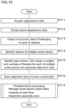
- FIG. 5 is a flowchart illustrating a screw construction inference method according to Embodiment 1.
- the arithmetic unit 11 of the screw construction inference device 1 acquires appearance data from the measurement device 2 via the communication unit 13 (step S111).
- the appearance data is data indicating the appearance of the screw 3 or the aligned multiple screw pieces 3a.
- the arithmetic unit 11 is assumed to use two-dimensional screw image data based on the appearance data.
- FIG. 6 is a schematic diagram illustrating an appearance data capture screen 131.
- the arithmetic unit 11 having acquired appearance data displays an appearance data capture screen 131 representing a screw image.
- the appearance data capture screen 131 includes a captured image display section 131a and a screw construction inference start button 131b.
- the arithmetic unit 11 displays a screw image at the captured image display section 131a on the basis of the acquired screw image data.
- the screw construction inference start button 131b is operated by the user, execution of the following screw construction inference processing is started.
- the arithmetic unit 11 inputs the screw image data to the object detection learning model 17 to output a feature map (step S112).
- the feature map includes information for specifying the position and class of an object contained in the screw image.
- the arithmetic unit 11 specifies the alignment positions and classes of the multiple screw pieces 3a on the basis of the feature map (step S113). Specifically, from the feature map, the coordinates of the central positions, the vertical and horizontal dimensions, object detection scores and class scores of the bounding boxes that respectively surround the multiple screw pieces 3a can be obtained. The arithmetic unit 11 specifies the positions, dimension and classes of the bounding boxes of the multiple screw pieces 3a based on the object detection scores and the class scores. For example, the class with the object detection score equal to or greater than a threshold and the highest-class score is specified.
- FIG. 7 is a conceptual diagram illustrating detection results of objects
- FIG. 8 is a table indicating detection results of objects.
- the rectangular frames each represent a bounding box, and the numerals "1," "2,” ... are numbers (No.) to respectively identify the specified screw pieces 3a.
- the central position of the bounding box is represented by the X coordinate and the Y coordinate.
- "FF" indicates the type of the screw piece 3a belonging to a specific class (forward flight piece).
- the arithmetic unit 11 then specifies the type names, L/Ds, leads or angles (lead angles) and the numbers of threads for each of the identified multiple screw pieces 3a and generates the alignment data (step S114). More specifically, the arithmetic unit 11 refers to the screw piece table 18 using each of the classes of the identified multiple screw pieces 3a as a key and specifies the L/D, the lead or angle and the number of threads for each of the multiple screw pieces 3a. The arithmetic unit 11 then stores alignment data of the screw construction in the storage unit 12 (step S115).
- FIG. 9 is a conceptual diagram illustrating alignment data of the screw construction.
- the alignment data is data in which the alignment order of the multiple screw pieces 3a constituting the screw 3 is associated with the D/L (the ratio of the length and diameter), the lead or lead angle and the number of threads for each of the multiple screw pieces 3a. "No.” in FIG. 9 conceptually indicates the alignment order of the multiple screw pieces 3a.
- the arithmetic unit 11 executes predetermined processing on the basis of the generated and stored alignment data of the screw construction (step S116).
- the arithmetic unit 11 can manage the screw pieces 3a by, for example, registering the alignment data of the screw construction in the database. For example, the information on the screw pieces 3a of the respective screws 3 loaded in one or more extruders A can be managed.
- the arithmetic unit 11 can perform behavior analysis of the extruder A and the analysis of resin flow based on the generated and stored alignment data of the screw 3.
- the arithmetic unit 11 can determine an assembly error of the multiple screw pieces 3a based on the alignment data.
- the storage unit 12 is assumed to store the alignment data of a normal screw 3. In other words, the storage unit 12 stores alignment data indicating a correct alignment order and types of the multiple screw pieces 3a.
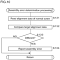
- FIG. 10 is a flowchart depicting an assembly error determination processing according to Embodiment 1.
- the arithmetic unit 11 reads alignment data of the normal screw 3 stored in the storage unit 12 (step S131).
- the arithmetic unit 11 compares the alignment data of the screw 3 to be determined that is obtained by the processing through step S111 to S114 and the alignment data of the normal screw 3 (step S132) and determines whether or not a difference is present (step S133). In other words, the arithmetic unit 11 compares the screw pieces 3a located in the same alignment order in the L/D, the lead, the angle and the number of threads.
- step S133: NO If determining that no difference is present (step S133: NO), the arithmetic unit 11 ends the assembly error determination processing. If determining that an assembly error is present (step S133: YES), the arithmetic unit 11 reports the presence of an assembly error (step S134) and ends the processing. For example, the arithmetic unit 11 displays the presence of an assembly error of the screw pieces 3a on the display unit 14.
- the arithmetic unit 11 may display the image of the screw 3, the image surrounding the screw piece 3a for which a difference is detected and the like, on the display unit 14.
- the arithmetic unit 11 may be configured to display the screw piece 3a at the location where an assembly error is present by changing the color of the screw partial image, for example.
- the arithmetic unit 11 may display the alignment order of the misassembled screw piece 3 and the type of the correct screw piece 3a, on the display unit 14.
- the screw construction inference device 1 may be equipped with a speaker or a light emitting device that, if detecting an assembly error of the screw pieces 3a, reports the presence of the assembly error to the user with sound or light.
- the screw construction inference device 1 may be configured to send report data for reporting an assembly error of the screw pieces 3a to a communication terminal of the user or a management device of the extruder A.
- the alignment positions and classes of the multiple screw pieces 3a constituting the normal screw 3 are compared with the alignment positions and classes of the multiple screw pieces 3a constituting the screw 3 to be determined that are obtained by the processing through S111 to S113 to determine whether or not a difference is present.
- the screw construction inference device 1 according to Embodiment 1 thus configured can infer the alignment positions and types of the multiple screw pieces 3a that constitute the screw 3 for the extruder A.
- the screw construction inference device 1 can generate alignment data in which the alignment order, the L/D, the lead, the angle and the number of threads of the multiple screw pieces 3a constituting the screw 3 are associated with each other.
- the alignment data of the screw 3, if obtained, can be used for the management of the screw pieces 3a or the analysis of resin flow in the extruder A.
- the screw construction inference device 1 can determine the presence or absence of an assembly error of the screw pieces 3a and can report the assembly error. Specifically, the alignment data of a correct screw construction is compared with the alignment data of the screw 3 to be determined to thereby determine an assembly error of the screw pieces 3a. This allows for determination of an assembly error of the screw pieces 3a without relying on human hands.
- the positions and types of the screw pieces 3a that constitute the screw 3 can be inferred with high precision.
- Embodiment 1 described an example where alignment data of the screw 3 is generated based on the appearance data obtained by taking an image of or measuring the distance from the screw 3, appearance data may be used that is obtained by taking an image of or measuring the distance from the multiple screw pieces 3a aligned before being assembled.
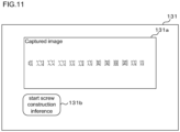
- FIG. 11 is a schematic diagram illustrating another example of a method of capturing appearance data.
- the arithmetic unit 11 acquires the screw image data obtained by taking an image of the multiple screw pieces 3a aligned with spaces as illustrated in FIG.11 .
- the arithmetic unit 11 inputs the screw image data to the object detection learning model 17 to thereby detect the multiple screw pieces 3a and obtain the alignment data of the screw 3.
- the boundary between screw pieces 3a may incorrectly be determined.
- more accurate alignment data may be detected.
- the multiple screw pieces 3a may be assigned with marks that enable image identification. This allows the arithmetic unit 11 to correctly recognize each of the multiple screw pieces 3a based on the images of the marks contained in the screw image.
- the screw pieces 3a may be assigned with different marks based on the types of the screw pieces 3a. This allows for detection of the alignment positions and types of the screw pieces 3a that constitute the screw 3 with higher precision.
- Embodiment 1 described an example where the two-dimensional screw image data is processed
- three-dimensional data may be used for generating alignment data.
- the three-dimensional data of the screw 3 can be obtained based on images taken from multiple different positions and angles using a camera or the like.
- the three-dimensional data of the screw 3 can also be obtained from the point group data obtained by measuring the distances.
- the arithmetic unit 11 can likewise detect an assembly error of the screw pieces 3a.
- the screw construction inference device 1 according to Embodiment 2 is different from that of Embodiment 1 in that an assembly error of the two screws 3 loaded in a twin-screw extruder is determined. Since the other configurations of the screw construction inference device 1 are similar to those of the screw construction inference device according to Embodiment 1, corresponding parts are designated by similar reference codes and detailed description thereof will not be made.
- the arithmetic unit 11 of the screw construction inference device 1 according to Embodiment 2 obtains appearance data of the two screws 3 loaded in the twin-screw extruder, generates alignment data of a first screw 3 and alignment data of a second screw 3 and stores them in the storage unit 12.
- FIG. 12 is a flowchart depicting an assembly error determination processing according to Embodiment 2.
- the arithmetic unit 11 reads the alignment data of the first screw 3 and the alignment data of the second screw 3 that are stored in the storage unit 12 (step S231).
- the arithmetic unit 11 then compares the alignment data of the respective screws 3 (step S232).
- the arithmetic unit 11 determines whether or not a difference is present in the alignment data of the first screw 3 and the second screw 3 (step S233). If determining that no difference is present (step S233: NO), the arithmetic unit 11 ends the assembly error determination processing. If determining that a difference is present (step S233: YES), the arithmetic unit 11 reports the presence of the assembly error (step S234) and ends the determination processing.
- the screw construction inference device 1 can determine the presence or absence of an assembly error by comparing the alignment data of the two screws 3 loaded in the twin-screw extruder, and can, if there is an assembly error, report it.
- the alignment positions and classes of the multiple screw pieces 3a constituting the first screw 3 may be compared with the alignment positions and classes of the multiple screw pieces 3a constituting the second screw 3.
- the arithmetic unit 11 can determine the difference between the construction of the first screw 3 and the construction of the second screw 3 by comparing the screws in the alignment positions and classes. This determination allows for detection of an assembly error of the screw 3.
- the screw construction inference device 1 according to Embodiment 3 is different from that of Embodiment 1 in the method of specifying the alignment order and the type of the screw pieces 3a. Since the other configurations of the screw construction inference device 1 are similar to those of the screw construction inference device in Embodiment 1, corresponding parts are designated by similar reference codes and detailed description thereof will not be made.
- FIG. 13 is a block diagram illustrating an example of the configuration of the screw construction inference device 1 according to Embodiment 3.
- the storage unit 12 of the screw construction inference device 1 according to Embodiment 3 stores a type recognition learning model 19 instead of the object detection learning model 17.
- FIG. 14 is a conceptual diagram illustrating a type recognition detection learning model according to Embodiment 3.
- the type recognition detection learning model is an image recognition model.
- the type recognition learning model 19 includes a convolutional neural network (CNN) having been trained by deep learning, for example.
- CNN convolutional neural network
- the configuration of the neural network itself is similar to that of the object detection learning model 17.
- the type recognition learning model 19 includes an input layer 19a that receives input of piece image data, which is data of an image part of the screw piece 3a, an intermediate layer 19b that extracts features of the piece image data, and an output layer 19c that outputs accuracy data indicating the accuracy of a piece image belonging to each of the multiple classes.
- a method of generating the type recognition learning model 19 is described. First, training data including multiple piece image data and teacher data indicating a class to which each piece image belongs are prepared. The class indicates a group classified depending on the type of the screw piece 3a. The arithmetic unit 11 then optimizes the weight coefficients of the neural network using, for example, error backpropagation and error gradient descent methods such that the error (value of a given loss function or error function) between data output, when a screw image of the training data is input to a CNN, from the CNN and data indicated by the teacher data is reduced, to thereby generate the type recognition learning model 19.
- error value of a given loss function or error function
- FIG. 15 is a flowchart depicting a screw construction inference method according to Embodiment 3.
- the arithmetic unit 11 of the screw construction inference device 1 acquires appearance data from the measurement device 2 via the communication unit 13 (step S311) and extracts piece appearance data corresponding to the piece image part (step S312).
- the arithmetic unit 11 is assumed to use two-dimensional screw image data based on the appearance data.
- image data obtained by taking an image of the multiple screw pieces 3a aligned with spaces is preferably used as screw image data.
- the piece appearance data is piece image data corresponding to the part of the screw piece 3a in the screw image.
- the arithmetic unit 11 extracts a piece image by the processing such as pattern matching or the like.
- the arithmetic unit 11 recognizes the position of the piece image by extracting the piece image. In other words, the arithmetic unit 11 detects the alignment position of each of the multiple screw pieces 3a.
- the arithmetic unit 11 inputs the extracted piece image to the type recognition learning model 19 and obtains output of the accuracy data indicating the accuracy of a piece image belonging to each of multiple classes (step S313).
- the arithmetic unit 11 specifies the classes of the multiple screw pieces 3a based on the accuracy data output from the type recognition learning model 19 (step S314).
- the arithmetic unit 11 generates alignment data of the screw 3 (step S315), stores it (step S316), and executes predetermined processing using the alignment data (step S316).
- the screw construction inference device1 according to Embodiment 3 can infer the alignment positions and types of the multiple screw pieces 3a that constitute the screw 3 for the extruder A, as in Embodiment 1.
- detection of a piece appearance image may also be executed using the machine learning model.
- three-dimensional data of the screw 3 may be used for arithmetic processing to thereby generate alignment data of the screw 3.
- Embodiments 1 to 3 described examples where the alignment positions and types of the multiple screw pieces 3a that constitute the screw 3 are inferred by mainly using a learning model, they may be inferred by performing rule-based image processing.
- the screw construction inference device 1 may be configured to infer the alignment positions and types of the screw pieces 3a by template matching processing.
- the storage unit 12 of the screw construction inference device 1 stores the template images of the multiple types of the screw pieces 3a and the types of screw pieces 3a in association with each other.
- the arithmetic unit 11 specifies the positions and types of the multiple screw pieces 3a contained in the screw image by the template matching processing using the template images stored in the storage unit 12.
- the processing to be performed after specifying the alignment positions and types of the multiple screw pieces 3a is similar to those described in Embodiment 1 to 3 as described above.
- the screw construction inference device 1 may be configured to infer the alignment positions and types of the screw pieces 3a based on the features.
- the storage unit 12 of the screw construction inference device 1 stores the features of the multiple types of the screw pieces 3a and the types of the screw pieces 3a in association with each other. Various types of features are conceivable including edges, shading changes and positional relationships between characteristic points.
- the arithmetic unit 11 specifies the positions and types of the multiple screw pieces 3a contained in the screw image in comparison with the features stored in the storage unit 12. The processing to be performed after specifying the alignment positions and types of the multiple screw pieces 3a is similar to those described in Embodiment 1 to 3 as described above.
Landscapes
- Engineering & Computer Science (AREA)
- Business, Economics & Management (AREA)
- Theoretical Computer Science (AREA)
- General Physics & Mathematics (AREA)
- Physics & Mathematics (AREA)
- Human Resources & Organizations (AREA)
- Mechanical Engineering (AREA)
- Economics (AREA)
- Strategic Management (AREA)
- Computer Vision & Pattern Recognition (AREA)
- Health & Medical Sciences (AREA)
- General Health & Medical Sciences (AREA)
- Multimedia (AREA)
- Quality & Reliability (AREA)
- Entrepreneurship & Innovation (AREA)
- Marketing (AREA)
- Tourism & Hospitality (AREA)
- General Business, Economics & Management (AREA)
- Development Economics (AREA)
- Operations Research (AREA)
- Game Theory and Decision Science (AREA)
- Educational Administration (AREA)
- Evolutionary Computation (AREA)
- Pathology (AREA)
- Immunology (AREA)
- Biochemistry (AREA)
- Analytical Chemistry (AREA)
- Chemical & Material Sciences (AREA)
- Life Sciences & Earth Sciences (AREA)
- Signal Processing (AREA)
- Software Systems (AREA)
- Medical Informatics (AREA)
- Databases & Information Systems (AREA)
- Computing Systems (AREA)
- Artificial Intelligence (AREA)
- Manufacturing & Machinery (AREA)
- Primary Health Care (AREA)
- Image Analysis (AREA)
- Extrusion Moulding Of Plastics Or The Like (AREA)
- Management, Administration, Business Operations System, And Electronic Commerce (AREA)
Applications Claiming Priority (2)
| Application Number | Priority Date | Filing Date | Title |
|---|---|---|---|
| JP2022060714A JP2023151221A (ja) | 2022-03-31 | 2022-03-31 | スクリュ構成推定装置、スクリュ構成推定方法及びコンピュータプログラム |
| PCT/JP2023/005092 WO2023188919A1 (fr) | 2022-03-31 | 2023-02-15 | Dispositif d'estimation de configuration de vis, procédé d'estimation de configuration de vis et programme informatique |
Publications (2)
| Publication Number | Publication Date |
|---|---|
| EP4502929A1 true EP4502929A1 (fr) | 2025-02-05 |
| EP4502929A4 EP4502929A4 (fr) | 2026-04-29 |
Family
ID=88200281
Family Applications (1)
| Application Number | Title | Priority Date | Filing Date |
|---|---|---|---|
| EP23778953.2A Pending EP4502929A4 (fr) | 2022-03-31 | 2023-02-15 | Dispositif d'estimation de configuration de vis, procédé d'estimation de configuration de vis et programme informatique |
Country Status (6)
| Country | Link |
|---|---|
| US (1) | US20250208056A1 (fr) |
| EP (1) | EP4502929A4 (fr) |
| JP (1) | JP2023151221A (fr) |
| CN (1) | CN118984768A (fr) |
| TW (1) | TW202402504A (fr) |
| WO (1) | WO2023188919A1 (fr) |
Family Cites Families (5)
| Publication number | Priority date | Publication date | Assignee | Title |
|---|---|---|---|---|
| FR2607431B1 (fr) * | 1986-12-02 | 1989-03-10 | Clextral | Procede et installation de montage et demontage des vis d'une machine d'extrusion |
| DE102013108335B4 (de) * | 2013-08-02 | 2017-06-22 | Leistritz Extrusionstechnik Gmbh | Extruder |
| DE102013112971B3 (de) * | 2013-11-25 | 2015-02-05 | Leistritz Extrusionstechnik Gmbh | Einrichtung und Verfahren zur Überprüfung des Aufbaus einer Extruderschnecke |
| JP6719347B2 (ja) | 2016-09-14 | 2020-07-08 | 株式会社日本製鋼所 | 二軸押出機 |
| WO2021255010A1 (fr) * | 2020-06-17 | 2021-12-23 | Bühler AG | Extrudeuse et procédé pour la surveillance de l'état d'une extrudeuse |
-
2022
- 2022-03-31 JP JP2022060714A patent/JP2023151221A/ja active Pending
-
2023
- 2023-02-15 EP EP23778953.2A patent/EP4502929A4/fr active Pending
- 2023-02-15 CN CN202380031730.5A patent/CN118984768A/zh active Pending
- 2023-02-15 US US18/851,425 patent/US20250208056A1/en active Pending
- 2023-02-15 WO PCT/JP2023/005092 patent/WO2023188919A1/fr not_active Ceased
- 2023-02-22 TW TW112106424A patent/TW202402504A/zh unknown
Also Published As
| Publication number | Publication date |
|---|---|
| CN118984768A (zh) | 2024-11-19 |
| TW202402504A (zh) | 2024-01-16 |
| US20250208056A1 (en) | 2025-06-26 |
| EP4502929A4 (fr) | 2026-04-29 |
| JP2023151221A (ja) | 2023-10-16 |
| WO2023188919A1 (fr) | 2023-10-05 |
Similar Documents
| Publication | Publication Date | Title |
|---|---|---|
| US12307699B2 (en) | Three-dimensional reconstruction method and three-dimensional reconstruction apparatus | |
| US10832039B2 (en) | Facial expression detection method, device and system, facial expression driving method, device and system, and storage medium | |
| US12430895B2 (en) | Method and apparatus for updating object recognition model | |
| US20250046111A1 (en) | Information processing apparatus, control method, and non-transitory storage medium | |
| CN112036339B (zh) | 人脸检测的方法、装置和电子设备 | |
| JP6684475B2 (ja) | 画像処理装置、画像処理方法及びプログラム | |
| US10945888B2 (en) | Intelligent blind guide method and apparatus | |
| US20230386185A1 (en) | Statistical model-based false detection removal algorithm from images | |
| Wang et al. | A smart operator advice model by deep learning for motion recognition in human–robot coexisting assembly line | |
| CN117173624A (zh) | 在计算装置中的对象识别模型学习方法 | |
| CN111723688A (zh) | 人体动作识别结果的评价方法、装置和电子设备 | |
| EP4502929A1 (fr) | Dispositif d'estimation de configuration de vis, procédé d'estimation de configuration de vis et programme informatique | |
| KR20230166865A (ko) | 영상에서 통계모델기반 오검출 제거 알고리즘 | |
| US20220172483A1 (en) | System and method social distancing recognition in cctv surveillance imagery | |
| EP4607477A1 (fr) | Détermination de la position du regard sur de multiples écrans à l'aide d'une caméra monoculaire | |
| JP7239002B2 (ja) | 物体数推定装置、制御方法、及びプログラム | |
| EP4502930A1 (fr) | Dispositif de détection d'erreur d'assemblage d'éléments de vis, procédé de détection d'erreur d'assemblage d'éléments de vis, et programme informatique | |
| JP2019066909A (ja) | 物体分布推定装置 | |
| US20240031680A1 (en) | Machine learning-based camera positioning | |
| JP7358269B2 (ja) | 物体検出装置、物体検出システム、および、物体検出方法 | |
| Horng et al. | Building an Adaptive Machine Learning Object-Positioning System in a Monocular Vision Environment | |
| US20260057702A1 (en) | Label generation for human activity recognition | |
| HK40100468A (zh) | 距离检测方法、装置、设备及存储介质 | |
| WO2022185481A1 (fr) | Appareil d'inspection, procédé d'inspection et support d'enregistrement | |
| CN115359246A (zh) | 图像处理方法、装置、设备及存储介质 |
Legal Events
| Date | Code | Title | Description |
|---|---|---|---|
| STAA | Information on the status of an ep patent application or granted ep patent |
Free format text: STATUS: THE INTERNATIONAL PUBLICATION HAS BEEN MADE |
|
| PUAI | Public reference made under article 153(3) epc to a published international application that has entered the european phase |
Free format text: ORIGINAL CODE: 0009012 |
|
| STAA | Information on the status of an ep patent application or granted ep patent |
Free format text: STATUS: REQUEST FOR EXAMINATION WAS MADE |
|
| 17P | Request for examination filed |
Effective date: 20241029 |
|
| AK | Designated contracting states |
Kind code of ref document: A1 Designated state(s): AL AT BE BG CH CY CZ DE DK EE ES FI FR GB GR HR HU IE IS IT LI LT LU LV MC ME MK MT NL NO PL PT RO RS SE SI SK SM TR |
|
| DAV | Request for validation of the european patent (deleted) | ||
| DAX | Request for extension of the european patent (deleted) | ||
| REG | Reference to a national code |
Ref country code: DE Ref legal event code: R079 Free format text: PREVIOUS MAIN CLASS: G06T0007000000 Ipc: B29C0048250000 |
|
| A4 | Supplementary search report drawn up and despatched |
Effective date: 20260331 |
|
| RIC1 | Information provided on ipc code assigned before grant |
Ipc: B29C 48/25 20190101AFI20260325BHEP Ipc: B29C 48/40 20190101ALI20260325BHEP Ipc: B29C 48/505 20190101ALI20260325BHEP Ipc: B29C 48/92 20190101ALI20260325BHEP Ipc: G06V 10/82 20220101ALI20260325BHEP |