EP4502985A1 - Laufzeitsicherungssystem für manuelle und automatisierte landungen - Google Patents
Laufzeitsicherungssystem für manuelle und automatisierte landungen Download PDFInfo
- Publication number
- EP4502985A1 EP4502985A1 EP24190986.0A EP24190986A EP4502985A1 EP 4502985 A1 EP4502985 A1 EP 4502985A1 EP 24190986 A EP24190986 A EP 24190986A EP 4502985 A1 EP4502985 A1 EP 4502985A1
- Authority
- EP
- European Patent Office
- Prior art keywords
- aircraft
- fpv
- fpp
- touch down
- down zone
- Prior art date
- Legal status (The legal status is an assumption and is not a legal conclusion. Google has not performed a legal analysis and makes no representation as to the accuracy of the status listed.)
- Pending
Links
Images


Classifications
-
- G—PHYSICS
- G08—SIGNALLING
- G08G—TRAFFIC CONTROL SYSTEMS
- G08G5/00—Traffic control systems for aircraft
- G08G5/50—Navigation or guidance aids
- G08G5/54—Navigation or guidance aids for approach or landing
-
- G—PHYSICS
- G05—CONTROLLING; REGULATING
- G05D—SYSTEMS FOR CONTROLLING OR REGULATING NON-ELECTRIC VARIABLES
- G05D1/00—Control of position, course, altitude or attitude of land, water, air or space vehicles, e.g. using automatic pilots
- G05D1/60—Intended control result
- G05D1/654—Landing
-
- B—PERFORMING OPERATIONS; TRANSPORTING
- B64—AIRCRAFT; AVIATION; COSMONAUTICS
- B64D—EQUIPMENT FOR FITTING IN OR TO AIRCRAFT; FLIGHT SUITS; PARACHUTES; ARRANGEMENT OR MOUNTING OF POWER PLANTS OR PROPULSION TRANSMISSIONS IN AIRCRAFT
- B64D45/00—Aircraft indicators or protectors not otherwise provided for
- B64D45/04—Landing aids; Safety measures to prevent collision with earth's surface
- B64D45/08—Landing aids; Safety measures to prevent collision with earth's surface optical
-
- G—PHYSICS
- G06—COMPUTING OR CALCULATING; COUNTING
- G06T—IMAGE DATA PROCESSING OR GENERATION, IN GENERAL
- G06T7/00—Image analysis
- G06T7/70—Determining position or orientation of objects or cameras
- G06T7/73—Determining position or orientation of objects or cameras using feature-based methods
-
- G—PHYSICS
- G06—COMPUTING OR CALCULATING; COUNTING
- G06V—IMAGE OR VIDEO RECOGNITION OR UNDERSTANDING
- G06V20/00—Scenes; Scene-specific elements
- G06V20/10—Terrestrial scenes
- G06V20/17—Terrestrial scenes taken from planes or by drones
-
- G—PHYSICS
- G08—SIGNALLING
- G08G—TRAFFIC CONTROL SYSTEMS
- G08G5/00—Traffic control systems for aircraft
- G08G5/20—Arrangements for acquiring, generating, sharing or displaying traffic information
- G08G5/21—Arrangements for acquiring, generating, sharing or displaying traffic information located onboard the aircraft
Definitions
- GNSS global navigation satellite systems
- GPS global positioning systems
- jamming purposeful interference
- inventions of the inventive concepts disclosed herein are directed to a system.
- the system may include at least one processor.
- the at least one processor may be configured to: obtain data of an aircraft, the aircraft performing an approach procedure, the data including and/or associated with flight path information, the flight path information including at least one of a flight path vector (FPV) or a flight path predictor (FPP); obtain image sensor data output by at least one image sensor of the aircraft, the image sensor data including data associated with at least one image of a view from the aircraft, the view at least partially in front of the aircraft; identify features associated with a runway, the features within one or more of the at least one image; determine that the identified features are indicative of the runway; determine a touch down zone on the runway, wherein the touch down zone is defined by toleranced boundary locations representing an acceptable touch down dispersion for the aircraft; compare the FPV and/or the FPP with the touch down zone to determine whether the FPV and/or the FPP is in the touch down zone when the aircraft is at a decision altitude and/or
- inventions of the inventive concepts disclosed herein are directed to a method.
- the method may include: obtaining, by at least one processor, the aircraft performing an approach procedure, the data including and/or associated with flight path information, the flight path information including at least one of a flight path vector (FPV) or a flight path predictor (FPP); obtaining, by the at least one processor, image sensor data output by at least one image sensor of the aircraft, the image sensor data including data associated with at least one image of a view from the aircraft, the view at least partially in front of the aircraft; identifying, by the at least one processor, features associated with a runway, the features within one or more of the at least one image; determining, by the at least one processor, that the identified features are indicative of the runway; determining, by the at least one processor, a touch down zone on the runway, wherein the touch down zone is defined by toleranced boundary locations representing an acceptable touch down dispersion for the aircraft; comparing, by the at least one processor, the FPV and/or the FPP with the
- inventive concepts are not limited in their application to the details of construction and the arrangement of the components or steps or methodologies set forth in the following description or illustrated in the drawings.
- inventive concepts disclosed herein may be practiced without these specific details.
- well-known features may not be described in detail to avoid unnecessarily complicating the instant disclosure.
- inventive concepts disclosed herein are capable of other embodiments or of being practiced or carried out in various ways. Also, it is to be understood that the phraseology and terminology employed herein is for the purpose of description and should not be regarded as limiting.
- a letter following a reference numeral is intended to reference an embodiment of the feature or element that may be similar, but not necessarily identical, to a previously described element or feature bearing the same reference numeral (e.g., 1, 1a, 1b).
- reference numeral e.g. 1, 1a, 1b
- Such shorthand notations are used for purposes of convenience only, and should not be construed to limit the inventive concepts disclosed herein in any way unless expressly stated to the contrary.
- any reference to "one embodiment,” or “some embodiments” means that a particular element, feature, structure, or characteristic described in connection with the embodiment is included in at least one embodiment of the inventive concepts disclosed herein.
- the appearances of the phrase “in some embodiments” in various places in the specification are not necessarily all referring to the same embodiment, and embodiments of the inventive concepts disclosed may include one or more of the features expressly described or inherently present herein, or any combination of sub-combination of two or more such features, along with any other features which may not necessarily be expressly described or inherently present in the instant disclosure.
- embodiments of the inventive concepts disclosed herein may be directed to a system (e.g., an aircraft system or a system including an aircraft and an offboard device) and a method configured to compare an aircraft's flight path vector (FPV) and/or flight path predictor (FPP) with a touch down zone to determine whether the FPV and/or the FPP is in the touch down zone when the aircraft is at a decision altitude and/or is predicted to be in the touch down zone when the aircraft will be at the decision altitude, make a go/no go decision and/or recommendation, and/or at least one of output a notification to user or perform and aircraft operation based on the go/no go decision and/or recommendation.
- FPV flight path vector
- FPP flight path predictor
- An FPV may be approximately instantaneous (e.g., instantaneous, or the FPV may be filtered or smoothed in some cases) projection of the current aircraft trajectory.
- the FPV can be readily depicted as angular offsets from an aircraft pitch angle and a lateral pointing angle (also known as a heading).
- the FPV may not project future states accurately when the aircraft is maneuvering (e.g., turning or changing roll or pitch angles).
- the FPV is where an aircraft is headed, which might not be where the aircraft is pointed.
- data of where the aircraft is headed could come from an inertial system, such as an inertial reference system (IRS), an attitude and heading reference system (AHARS), and/or other sensors and/or systems, such as microelectromechanical systems (MEMSs), of the aircraft capable of measuring and reporting aircraft accelerations, velocities, and/or orientation.
- IRS inertial reference system
- AHARS attitude and heading reference system
- MEMSs microelectromechanical systems
- An FPP may add compensation terms to the FPV, for example, wherein such compensation terms may be and/or may be based on bank angle, turn rate, pitch rate, lateral and/or vertical accelerations and/or the like, to indicate a projected future state.
- the projected future state may be around 30 seconds into the future past the current trajectory associated with the flight path vector.
- Some embodiments may include monitoring a time history behavior of the FPV and/or the FPP to determine if the approach is progressing in a stable fashion. For example, large, rapid and/or erratic movements of the FPV and/or the FPP may be an indicator of an unstable approach even if the movements of the FPV and/or the FPP do not extend beyond an identified touchdown zone.
- the sensitivity of the system to these behaviors can be adjusted based on several conditions, such as how close a nominal or average position of the FPV and/or the FPP is to a center of the touchdown zone, proximity of the aircraft to the touchdown zone (e.g., determined directly or indirectly through parameters, such as image size or radar altimeter information), and/or a general trend of excursions from a nominal position of the FPV and/or the FPP (e.g., the system could be more sensitive to excursions trending to land short more often than land long.)
- the system e.g., at least one processor of the system
- Some embodiments may provide at least one onboard and/or offboard processor configured to execute a run-time assurance monitor for approaches to any runway, whereby the at least one onboard and/or offboard processor may make a go/no-go decision for landings independent of instrument landing system (ILS) landing guidance and/or independent of GNSS landing guidance.
- ILS instrument landing system
- Some embodiments may include at least one forward-looking image sensor (e.g., at least one electromagnetic (EM) image sensor; e.g., a radar system and/or a camera) installed on an aircraft, wherein the at least one image sensor may be configured to sense electromagnetic energy (e.g., light and/or radio waves) and output corresponding image data associated with images.
- EM electromagnetic
- Some embodiments may include the use of at least one processor to perform computer vision techniques to recognize runway features (e.g., a runway threshold of a runway, left and/or right edges of the runway, a centerline of the runway, runway approach and landing lights, and/or airport lights for a runway of the airport) within the images so as to identify a runway, determine a touch down zone of the runway, and overlay the touch down zone on the images.
- identification of the runway may include accessing and referencing information contained within a runway database to obtain information associated the runway, such as to manage misplaced runway thresholds.
- the touch down zone may be defined by toleranced boundary locations representing an acceptable touch down dispersion (which may vary based on specific information associated with a given aircraft, given environmental conditions, and/or given runway conditions) for the aircraft.
- Some embodiments may include at least one processor configured to use data (e.g., including and/or associated with flight path information) to project an FPV and/or an FPP into a visual scene.
- data e.g., including and/or associated with flight path information
- Some embodiments may include at least one processor configured to use vertical and lateral offset errors of the FPP and/or the FPV relative to the touch down zone location as a run-time assurance monitor. For example, if the aircraft is on an approach path (e.g., as determined based at least on data obtained from the ILS and/or GNSS device and/or data associated with a flight management system (FMS) and/or an auto-landing system) and if a center of the FPV and/or the FPP is located within the touch down zone in an image, the landing procedure can continue (e.g., so long as no other run time assurance condition triggers a go-around decision or recommendation).
- FMS flight management system
- the aircraft can continue the approach until a radar altimeter and/or barometer (as may be appropriate to an approach) indicates reaching a decision altitude. For example, a go-around may be triggered whenever the run-time assurance monitor conditions are not satisfied.
- Some embodiments do not need to (beyond possibly identifying when thresholds are displaced) rely on a navigation system's (e.g., GPS and/or ILS) position information such that such embodiments can provide a go/no-go decision independent of such navigation systems and such that such embodiments can provide sufficient runtime assurance to enable fully automated landings on runways without needing Category III landing systems (e.g., Category IIIB ILSs).
- a navigation system's e.g., GPS and/or ILS
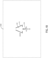
- the images 102A, 102B may include a runway 103 and/or features (e.g., at least one runway edge 104, at least one runway threshold 108, at least one runway centerline 106, or at least one runway and approach light (e.g., at least one approach light 110 and/or at least one runway light 112)) associated with the runway 103.
- at least one processor may be configured to obtain image sensor data output by at least one image sensor of an aircraft, the image sensor data including data associated with at least one image of a view from the aircraft, the view at least partially in front of the aircraft.
- FIG. 1A shows the image 102A captured in day-time.
- FIG. 1B shows the image 102B captured at night.
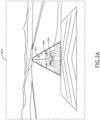
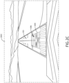
- At least one processor may be configured to: generate at least one display image based at least on image sensor data, a runway, a touch down zone, and/or an FPV and/or an FPP.
- each of the at least one display image 202A, 202B, 202C, 202D may include a given image of at least one image of the view from the aircraft, the runway 103, a touch down zone indicator 204 associated with the touch down zone, and/or an FPV and/or FPP indicator 206 associated with the FPP.
- the FPV and/or FPP indicator 206 may include graphical elements that graphical convey information about lateral offset errors and a center of the FPV and/or FPP indicator 206, wherein such graphical elements may be present in the exemplary cross-shaped FPV and/or FPP indicator 206.
- FIG. 2A shows the display image 202A corresponding to a day-time approach.
- FIG. 2B shows the display image 202B corresponding to a night-time approach.
- FIG. 2C shows the display image 202C corresponding to a day-time approach.
- FIG. 2D shows the display image 202D corresponding to a night-time approach.
- the system may include an aircraft 302 and/or at least one offboard platform 320, some or all of which may be communicatively coupled at any given time.
- the aircraft 302 may include at least one onboard pilot and may be a single-piloted or multiple-piloted aircraft; in some embodiments, the aircraft 302 may be an uncrewed aerial system (UAS) (e.g., a remote-piloted UAS and/or an autonomous UAS).
- UAS uncrewed aerial system
- the aircraft 302 may include at least one user (e.g., flight crew and/or pilot(s)), at least one display unit computing device 304, at least one computing device 306, at least one aircraft computing device 308, at least one user interface 310, at least one inertial system 312, at least one AHARS, at least one MEMS device, at least one image sensor 314, at least one instrument landing system (ILS) 316, and/or at least one GNSS device 318, some or all of which may be communicatively coupled at any given time.
- at least one user e.g., flight crew and/or pilot(s)
- at least one display unit computing device 304 e.g., at least one computing device 306, at least one aircraft computing device 308, at least one user interface 310, at least one inertial system 312, at least one AHARS, at least one MEMS device, at least one image sensor 314, at least one instrument landing system (ILS) 316, and/or at least one GNSS device 318, some or all of which
- the at least one display unit computing device 304, the at least one computing device 306, the at least one aircraft computing device 308, the at least one user interface 310, the at least one inertial system 312, the at least one image sensor 314, the at least one instrument landing system (ILS) 316, the at least one GNSS device 318, the at least one computing device 322, the at least one display unit computing device 324, and/or the at least one user interface 326 may be implemented as a single computing device or any number of computing devices configured to perform (e.g., collectively perform if more than one computing device) any or all of the operations disclosed throughout.
- ILS instrument landing system
- the at least one display unit computing device 304, the at least one computing device 306, the at least one aircraft computing device 308, the at least one user interface 310, the at least one computing device 322, the at least one display unit computing device 324, and/or the at least one user interface 326 may be installed in the aircraft 302, the offboard platform 320, or some combination thereof.
- the user may be a pilot or crew member, who may be located onboard the aircraft 302 or at the offboard platform 320.
- the user may interface with the system 300 via the at least one user interface 310.
- the at least one user interface 310 may be implemented as any suitable user interface, such as a touchscreen (e.g., of the display unit computing device 304 and/or another display unit), a multipurpose control panel, a control panel integrated into a flight deck, a cursor control panel (CCP) (sometimes referred to as a display control panel (DCP)), a keyboard, a mouse, a trackpad, at least one hardware button, a switch, an eye tracking system, and/or a voice recognition system.
- a touchscreen e.g., of the display unit computing device 304 and/or another display unit
- CCP cursor control panel
- DCP display control panel
- the user interface 310 may be configured to receive at least one user input and to output the at least one user input to a computing device (e.g., 304, 306, 308, 322, 324, and/or 326).
- a pilot of the aircraft 302 may be able to interface with the user interface 310 to: engage (or disengage) a mode to cause the display image 200A, 200B, 200C, and/or 200D to be displayed.
- such user inputs may be output to a computing device (e.g., 304, 306, 308, 322, 324, and/or 326).
- the display unit computing device 304 may be implemented as any suitable computing device, such as a primary flight display (PFD) computing device and/or a multi-function window (MFW) display computing device. As shown in FIG. 4 , the display unit computing device 304 may include at least one display 402, at least one processor 404, at least one memory 406, and/or at least one storage 410, some or all of which may be communicatively coupled at any given time.
- PFD primary flight display
- MMW multi-function window
- the at least one processor 404 may include at least one central processing unit (CPU), at least one graphics processing unit (GPU), at least one field-programmable gate array (FPGA), at least one application specific integrated circuit (ASIC), at least one digital signal processor, at least one virtual machine (VM) running on at least one processor, and/or the like configured to perform (e.g., collectively perform) any of the operations disclosed throughout.
- the at least one processor 404 may include a CPU and a GPU configured to perform (e.g., collectively perform) any of the operations disclosed throughout.
- the processor 404 may be configured to run various software applications or computer code stored (e.g., maintained) in a non-transitory computer-readable medium (e.g., memory 406 and/or storage 410) and configured to execute various instructions or operations.
- the processor 404 may be configured to perform any or all of the operations disclosed throughout.
- the at least one processor 404 may be configured to: obtain data of an aircraft 302, the aircraft 302 performing an approach procedure, the data including and/or associated with flight path information, the flight path information including at least one of a flight path vector (FPV) or a flight path predictor (FPP); obtain image sensor data output by at least one image sensor 314 of the aircraft 302, the image sensor data including data associated with at least one image 102A, 102B of a view from the aircraft 302, the view at least partially in front of the aircraft 302; identify features associated with a runway 103, the features within one or more of the at least one image 102A, 102B; determine that the identified features are indicative of the runway 103; determine a touch down zone 202 on the runway 103, wherein the touch down zone 202 is defined by toleranced boundary locations representing an acceptable touch down dispersion for the aircraft 302; compare the FPV and/or the FPP with the touch down zone 202 to determine whether the FPV and/or the FPP is in the touch down zone
- the at least one processor 404 may be configured to and/or further configured to: generate at least one display image 202A, 202B, 202C, and/or 202D based at least on the image sensor data, the runway 103, the touch down zone, and the FPV and/or the FPP; and/or output the at least one display image 202A, 202B, 202C, and/or 202D to the at least one display 402 for presentation to the user, each of the at least one display image 202A, 202B, 202C, and/or 202D including a given image of the at least one image 102A, 102B, 102C, and/or 102D of the view from the aircraft 302, the runway 103, a touch down zone indicator 204 associated with the touch down zone, and an FPV and/or FPP indicator 206 associated with the FPV and/or the FPP.
- the at least one display 402 may be configured to: display the at least one display image 202A, 202C,
- the data may include and/or may be associated with flight path information, which may be output to the at least one processor 404, 502 by the inertial system 312, the AHARS, a MEMS device, or the like.
- the at least one computing device 306 may be implemented as any suitable computing device.
- the at least one computing device 306 may include any or all of the elements shown in FIG. 5 .
- the computing device 306 may at least one processor 502, at least one memory 504, and/or at least one storage 506, some or all of which may be communicatively coupled at any given time.
- the at least one processor 502 may include at least one central processing unit (CPU), at least one graphics processing unit (GPU), at least one field-programmable gate array (FPGA), at least one application specific integrated circuit (ASIC), at least one digital signal processor, at least one virtual machine (VM) running on at least one processor, and/or the like configured to perform (e.g., collectively perform) any of the operations disclosed throughout.
- CPU central processing unit
- GPU graphics processing unit
- FPGA field-programmable gate array
- ASIC application specific integrated circuit
- VM virtual machine running on at least one processor, and/or the like configured to perform (e.g., collectively perform) any of the
- the at least one processor 502 may include a CPU and a GPU configured to perform (e.g., collectively perform) any of the operations disclosed throughout.
- the processor 502 may be configured to run various software applications (e.g., an ADS-B application and/or a radar application) or computer code stored (e.g., maintained) in a non-transitory computer-readable medium (e.g., memory 504 and/or storage 506) and configured to execute various instructions or operations.
- the processor 502 of the computing device 306 may be configured to perform any or all of the operations disclosed throughout.
- the at least one processor 502 may be configured to recognize, identify, and/or classify objects or features (e.g., runway edges 104, runway threshold 108, and/or runway and approach lights (e.g., 110 and/or 112)) in an image or video using image processing techniques, such as various approaches for feature extraction and/or pattern recognition.
- the at least one processor 502 may be configured to project the aircraft's flight path relative to the aircraft orientation.
- the at least one processor 502 may be configured to perform a comparison of the projected flight path to a touch down zone determined based on recognized images.
- the at least one processor 502 may be configured to output at least one notification (e.g., at least one alert) based on any various of conditions, such as the flight path is not projected to be within the identified touch down zone for an extended period of time, the flight path projection is within the identified touchdown zone but is not stable in lateral or vertical axis for an extended period of time, and/or the touch down zone is not identified in the image.
- at least one notification e.g., at least one alert
- the at least one processor 502 may be configured to: obtain data of an aircraft 302, the aircraft 302 performing an approach procedure, the data including and/or associated with flight path information, the flight path information including at least one of a flight path vector (FPV) or a flight path predictor (FPP); obtain image sensor data output by at least one image sensor 314 of the aircraft 302, the image sensor data including data associated with at least one image 102A, 102B of a view from the aircraft 302, the view at least partially in front of the aircraft 302; identify features associated with a runway 103, the features within one or more of the at least one image 102A, 102B; determine that the identified features are indicative of the runway 103; determine a touch down zone 202 on the runway 103, wherein the touch down zone 202 is defined by toleranced boundary locations representing an acceptable touch down dispersion for the aircraft 302; compare the FPV and/or the FPP with the touch down zone 202 to determine whether the FPV and/or the FPP is in the touch down zone
- the at least one computing device 308 may be implemented as any suitable computing device.
- the at least one computing device 308 may include any or all of the elements shown in FIG. 5 .
- the computing device 308 may at least one processor 502, at least one memory 504, and/or at least one storage 506, some or all of which may be communicatively coupled at any given time.
- the at least one processor 502 may include at least one central processing unit (CPU), at least one graphics processing unit (GPU), at least one field-programmable gate array (FPGA), at least one application specific integrated circuit (ASIC), at least one digital signal processor, at least one virtual machine (VM) running on at least one processor, and/or the like configured to perform (e.g., collectively perform) any of the operations disclosed throughout.
- CPU central processing unit
- GPU graphics processing unit
- FPGA field-programmable gate array
- ASIC application specific integrated circuit
- VM virtual machine running on at least one processor, and/or the like configured to perform (e.g., collectively perform) any of the
- the at least one processor 502 may include a CPU and a GPU configured to perform (e.g., collectively perform) any of the operations disclosed throughout.
- the processor 502 may be configured to run various software applications (e.g., an ADS-B application and/or a radar application) or computer code stored (e.g., maintained) in a non-transitory computer-readable medium (e.g., memory 504 and/or storage 506) and configured to execute various instructions or operations.
- the at least one processor 502 of the computing device 308 may be configured to perform any or all of the operations disclosed throughout.
- the at least one inertial system 312 may be any suitable inertial system or combination of inertial systems, such as at least one inertial reference unit (IRU) and/or at least one inertial measurement system (IMS).
- the at least one inertial system 312 may include at least one sensor (e.g., at least one gyroscope and/or at least one accelerometer) and electronics such that the at least one inertial system 312 may be configured to provide the data (e.g., including and/or associated with flight path information, the flight path information including at least one of a flight path vector (FPV) or a flight path predictor (FPP)), which may include information associated with attitude, velocity, and/or acceleration of the aircraft 302.
- FPV flight path vector
- FPP flight path predictor
- the at least one image sensor 314 may be any suitable image sensor or combination of image sensor, such as at least one forward-looking image sensor.
- the at least one image sensor 314 may be at least one electromagnetic (EM) image sensor, such as at least one radar system and/or at least one camera installed on the aircraft 302.
- the at least one image sensor 314 may be configured to sense electromagnetic energy (e.g., light and/or radio waves) and output corresponding image data associated with images.
- the at least one image sensor 314 may be able to receive incoming light and/or radio frequency signals into an electrical signal that can be viewed and analyzed.
- Some image sensors 314 may be configured to emit a signal and listen for reflections, and other image sensors may rely on the signals emitted or reflected from objects in the field of view.
- the at least one offboard platform 320 may be any suitable offboard site (e.g., a ground site, such as an air traffic control tower) and/or offboard mobile platform (e.g., another vehicle).
- the offboard platform 320 may include at least one user (e.g., flight crew and/or pilot(s)), at least one computing device 322, at least one display unit computing device 324, and/or at least one user interface 326, some or all of which may be communicatively coupled at any given time.
- the at least one computing device 322 may be configured similarly and function similarly to the at least one computing device 306 of the aircraft 302, except that the at least one computing device 322 is located offboard of the aircraft 302.
- the at least one display unit computing device 324 may be configured similarly and function similarly to the at least one display unit computing device 304 of the aircraft 302, except that the at least one display unit computing device 324 is located offboard of the aircraft 302.
- the at least one user interface 326 may be configured similarly and function similarly to the at least one user interface 310 of the aircraft 302, except that the at least one user interface 326 is located offboard of the aircraft 302.
- At least one processor may be configured to (e.g., collectively configured to, if more than one processor): obtain data of an aircraft 302, the aircraft 302 performing an approach procedure, the data including and/or associated with flight path information, the flight path information including at least one of a flight path vector (FPV) or a flight path predictor (FPP); obtain image sensor data output by at least one image sensor 314 of the aircraft 302, the image sensor data including data associated with at least one image 102A, 102B of a view from the aircraft 302, the view at least partially in front of the aircraft 302; identify features associated with a runway 103, the features within one or more of the at least one image 102A, 102B; determine that the identified features are indicative of the runway
- the features associated with the runway 103 may include at least one of: at least one runway edge 104, at least one runway surface marking (e.g., at least one runway threshold 108, at least one runway centerline 106, runway designation, at least one runway touchdown zone, at least one runway aiming point, and/or at least one runway side stripe) or at least one runway and approach light (e.g., 110 and/or 112; runway lights, centerline lights, threshold lights, and/or approach lights).
- the runway threshold is the beginning of the runway surface that is available for landing; the runway threshold does not need to correspond to the beginning of the paved surface; there are standardized markings to indicate the runway threshold.
- the aircraft 302 may be performing the approach procedure during day-time, and the features associated with the runway 103 may include at least one of: at least one runway edge 104, at least one runway threshold 108, or at least one runway centerline 106.
- the aircraft 302 may be performing the approach procedure at night, and the features associated with the runway 103 include at least one runway and approach light (e.g., 110 and/or 112).
- the at least one processor may be further configured to (e.g., collectively configured to, if more than one processor): compare the FPV and/or the FPP with the touch down zone 202 to determine whether a center of the FPV and/or the FPP is in the touch down zone 202 when the aircraft 302 is at a decision altitude and/or is predicted to be in the touch down zone 202 when the aircraft 302 will be at the decision altitude; and/or at least one of: (a) at least one of: (i) upon a determination that the center of the FPV and/or the FPP is in and/or is predicted to be in the touch down zone 202 at the decision altitude, output a notification for presentation to a user to proceed
- the at least one processor may be further configured to (e.g., collectively configured to, if more than one processor): upon the determination that the FPV and/or the FPP is in and/or is predicted to be in the touch down zone at the decision altitude, output the notification for presentation to the user to proceed with the landing procedure.
- the at least one processor may be further configured to (e.g., collectively configured to, if more than one processor): upon the determination that the FPV and/or the FPP is in and/or is predicted to be in the touch down zone at the decision altitude, perform the operation configured to cause the aircraft to proceed with the landing procedure.
- the at least one processor may be further configured to (e.g., collectively configured to, if more than one processor): upon the determination that the FPV and/or the FPP is not in and/or is not predicted to be in the touch down zone at the decision altitude, output the notification for presentation to the user to perform the go-around procedure.
- the at least one processor may be further configured to (e.g., collectively configured to, if more than one processor): upon the determination that the FPV and/or the FPP is not in and/or is not predicted to be in the touch down zone at the decision altitude, perform the operation configured to cause the aircraft to perform the go-around procedure.
- the at least one processor may be further configured to (e.g., collectively configured to, if more than one processor): generate at least one display image based at least on the image sensor data, the runway, the touch down zone, and the FPV and/or the FPP; and/or output the at least one display image to the at least one display for presentation to the user, each of the at least one display image including a given image of the at least one image of the view from the aircraft, the runway, a touch down zone indicator associated with the touch down zone, and an FPV and/or FPP indicator associated with the FPV and/or the FPP.
- the at least one display 402 may be configured to: display the at least one display image to the user.
- the system 300 may include the aircraft 302, and the aircraft 302 may include: the at least one processor, the at least one inertial system, the at least one image sensor, and/or the at least one display; the user may be the pilot; and the at least one processor may be configured to: upon the determination that the FPV and/or the FPP is in and/or is predicted to be in the touch down zone at the decision altitude, output the notification to the pilot to proceed with the landing procedure, or (b) upon the determination that the FPV and/or the FPP is not in and/or is not predicted to be in the touch down zone at the decision altitude, output the notification for presentation to the user to perform the go-around procedure.
- the aircraft 302 includes at least one global navigation satellite system (GNSS) device 318, and the at least one GNSS device 318 may be compromised (e.g., jammed) and/or determined to be inaccurate (e.g., due to spoofing) during the performance of the approach procedure.
- GNSS global navigation satellite system
- the aircraft 302 includes at least one of at least one instrument landing system (ILS) 316 or at least one global navigation satellite system (GNSS) device 318, and the at least one processor (e.g., the at least one processor 404 (e.g., of the at least one display unit computing device 304 and/or 324) and/or the at least one processor 502 (e.g., of the at least one computing device 306, 308, and/or 322)) may be further configured to (e.g., collectively configured to, if more than one processor), independent of landing guidance provided by the at least one of the at least one ILS 316 or the at least one GNSS device 318, at least one of: (a) at least one of: (i) upon the determination that the FPV and/or the FPP is in and/or is predicted to be in the touch down zone at the decision altitude, output the notification for presentation to the user to proceed with the landing procedure, or (ii) upon the determination that the FPV and/or the FPP is
- the aircraft 302 lacks a Category IIIB landing system.
- the at least one processor may be further configured to (e.g., collectively configured to, if more than one processor): monitor the FPV and/or the FPP relative to the touch down zone over a trailing time duration during the approach procedure to obtain a metric of stability; determine whether the metric of stability is acceptable as compared to a predetermined stability metric threshold; and/or at least one of: (a) at least one of: (i) upon a determination that the FPV and/or the FPP is in and/or is predicted to be in the touch down zone at the decision altitude and upon a determination that the metric of stability is acceptable, output a notification for presentation to a user to proceed with a landing procedure, or (ii) upon the determination that
- the at least one processor may be configured to (e.g., collectively configured to, if more than one processor) perform any or all of the operations disclosed throughout.
- an exemplary embodiment of a method 600 may include one or more of the following steps. Additionally, for example, some embodiments may include performing one or more instances of the method 600 iteratively, concurrently, and/or sequentially. Additionally, for example, at least some of the steps of the method 600 may be performed in parallel and/or concurrently. Additionally, in some embodiments, at least some of the steps of the method 600 may be performed non-sequentially.
- a step 602 may include obtaining, by at least one processor, data of an aircraft, the aircraft performing an approach procedure, the data including and/or associated with flight path information, the flight path information including at least one of a flight path vector (FPV) or a flight path predictor (FPP).
- FPV flight path vector
- FPP flight path predictor
- a step 604 may include obtaining, by the at least one processor, image sensor data output by at least one image sensor of the aircraft, the image sensor data including data associated with at least one image of a view from the aircraft, the view at least partially in front of the aircraft.
- a step 606 may include identifying, by the at least one processor, features associated with a runway, the features within one or more of the at least one image.
- a step 608 may include determining, by the at least one processor, that the identified features are indicative of the runway.
- a step 610 may include determining, by the at least one processor, a touch down zone on the runway, wherein the touch down zone is defined by toleranced boundary locations representing an acceptable touch down dispersion for the aircraft.
- a step 612 may include comparing, by the at least one processor, the FPV and/or the FPP with the touch down zone to determine whether the FPV and/or the FPP is in the touch down zone when the aircraft is at a decision altitude and/or is predicted to be in the touch down zone when the aircraft will be at the decision altitude.
- a step 614 may include by the at least one processor, at least one of: (a) at least one of: (i) upon a determination that the FPV and/or the FPP is in and/or is predicted to be in the touch down zone at the decision altitude, outputting a notification for presentation to a user to proceed with a landing procedure, or (ii) upon the determination that the FPV and/or the FPP is in and/or is predicted to be in the touch down zone at the decision altitude, performing an operation configured to cause the aircraft to proceed with the landing procedure; or (b) at least one of: (i) upon a determination that the FPV and/or the FPP is not in and/or is not predicted to be in the touch down zone at the decision altitude, outputting a notification for presentation to the user to perform a go-around procedure, or (ii) upon the determination that the FPV and/or the FPP is not in and/or is not predicted to be in the touch down zone at the decision altitude, performing an operation configured to cause the aircraft
- method 600 may include any of the operations disclosed throughout.
- embodiments of the inventive concepts disclosed herein may be directed to a system (e.g., an aircraft system or a system including an aircraft and an offboard device) and a method configured to compare an aircraft's flight path predictor (FPP) with a touch down zone to determine whether the FPP is in the touch down zone when the aircraft is at a decision altitude and/or is predicted to be in the touch down zone when the aircraft will be at the decision altitude, make a go/no go decision and/or recommendation, and/or at least one of output a notification to user or perform and aircraft operation based on the go/no go decision and/or recommendation.
- FPP flight path predictor
- At least one non-transitory computer-readable medium may refer to as at least one non-transitory computer-readable medium (e.g., at least one computer-readable medium implemented as hardware; e.g., at least one non-transitory processor-readable medium, at least one memory (e.g., at least one nonvolatile memory, at least one volatile memory, or a combination thereof; e.g., at least one random-access memory, at least one flash memory, at least one read-only memory (ROM) (e.g., at least one electrically erasable programmable read-only memory (EEPROM)), at least one on-processor memory (e.g., at least one on-processor cache, at least one on-processor buffer, at least one on-processor flash memory, at least one on-processor EEPROM, or a combination thereof), or a combination thereof), at least one storage device (e.g., at least one hard-disk drive, at
- At least one means one or a plurality of; for example, “at least one” may comprise one, two, three, ... , one hundred, or more.
- one or more means one or a plurality of; for example, “one or more” may comprise one, two, three, ... , one hundred, or more.
- zero or more means zero, one, or a plurality of; for example, “zero or more” may comprise zero, one, two, three, ... , one hundred, or more.
- the methods, operations, and/or functionality disclosed may be implemented as sets of instructions or software readable by a device. Further, it is understood that the specific order or hierarchy of steps in the methods, operations, and/or functionality disclosed are examples of exemplary approaches. Based upon design preferences, it is understood that the specific order or hierarchy of steps in the methods, operations, and/or functionality can be rearranged while remaining within the scope of the inventive concepts disclosed herein.
- the accompanying claims may present elements of the various steps in a sample order, and are not necessarily meant to be limited to the specific order or hierarchy presented.
- embodiments of the methods according to the inventive concepts disclosed herein may include one or more of the steps described herein. Further, such steps may be carried out in any desired order and two or more of the steps may be carried out simultaneously with one another. Two or more of the steps disclosed herein may be combined in a single step, and in some embodiments, one or more of the steps may be carried out as two or more sub-steps. Further, other steps or sub-steps may be carried in addition to, or as substitutes to one or more of the steps disclosed herein.
Landscapes
- Engineering & Computer Science (AREA)
- Physics & Mathematics (AREA)
- General Physics & Mathematics (AREA)
- Aviation & Aerospace Engineering (AREA)
- Remote Sensing (AREA)
- Theoretical Computer Science (AREA)
- Radar, Positioning & Navigation (AREA)
- Automation & Control Theory (AREA)
- Multimedia (AREA)
- Computer Vision & Pattern Recognition (AREA)
- Traffic Control Systems (AREA)
Applications Claiming Priority (1)
| Application Number | Priority Date | Filing Date | Title |
|---|---|---|---|
| US18/229,347 US20250044810A1 (en) | 2023-08-02 | 2023-08-02 | Runtime assurance system for manual and automated landings |
Publications (1)
| Publication Number | Publication Date |
|---|---|
| EP4502985A1 true EP4502985A1 (de) | 2025-02-05 |
Family
ID=92043261
Family Applications (1)
| Application Number | Title | Priority Date | Filing Date |
|---|---|---|---|
| EP24190986.0A Pending EP4502985A1 (de) | 2023-08-02 | 2024-07-25 | Laufzeitsicherungssystem für manuelle und automatisierte landungen |
Country Status (2)
| Country | Link |
|---|---|
| US (1) | US20250044810A1 (de) |
| EP (1) | EP4502985A1 (de) |
Families Citing this family (1)
| Publication number | Priority date | Publication date | Assignee | Title |
|---|---|---|---|---|
| AU2022380638B2 (en) * | 2021-08-19 | 2024-11-28 | Merlin Labs, Inc. | Advanced flight processing system and/or method |
Citations (4)
| Publication number | Priority date | Publication date | Assignee | Title |
|---|---|---|---|---|
| US20220258880A1 (en) * | 2021-02-17 | 2022-08-18 | Merlin Labs, Inc. | Method for aircraft localization and control |
| US20220315242A1 (en) * | 2021-03-30 | 2022-10-06 | Honeywell International Inc. | System and method for visual aided landing |
| US20230023069A1 (en) * | 2021-07-23 | 2023-01-26 | Xwing, Inc. | Vision-based landing system |
| EP4181104A1 (de) * | 2021-11-15 | 2023-05-17 | Honeywell International Inc. | Systeme und verfahren zur bereitstellung einer sicheren landehilfe für ein fahrzeug |
Family Cites Families (2)
| Publication number | Priority date | Publication date | Assignee | Title |
|---|---|---|---|---|
| US10793286B1 (en) * | 2018-08-23 | 2020-10-06 | Rockwell Collins, Inc. | Vision based autonomous landing using flight path vector |
| US11532237B2 (en) * | 2019-02-28 | 2022-12-20 | Rockwell Collins, Inc. | Autonomous aircraft sensor-based positioning and navigation system using markers |
-
2023
- 2023-08-02 US US18/229,347 patent/US20250044810A1/en active Pending
-
2024
- 2024-07-25 EP EP24190986.0A patent/EP4502985A1/de active Pending
Patent Citations (4)
| Publication number | Priority date | Publication date | Assignee | Title |
|---|---|---|---|---|
| US20220258880A1 (en) * | 2021-02-17 | 2022-08-18 | Merlin Labs, Inc. | Method for aircraft localization and control |
| US20220315242A1 (en) * | 2021-03-30 | 2022-10-06 | Honeywell International Inc. | System and method for visual aided landing |
| US20230023069A1 (en) * | 2021-07-23 | 2023-01-26 | Xwing, Inc. | Vision-based landing system |
| EP4181104A1 (de) * | 2021-11-15 | 2023-05-17 | Honeywell International Inc. | Systeme und verfahren zur bereitstellung einer sicheren landehilfe für ein fahrzeug |
Also Published As
| Publication number | Publication date |
|---|---|
| US20250044810A1 (en) | 2025-02-06 |
Similar Documents
| Publication | Publication Date | Title |
|---|---|---|
| US8742952B1 (en) | Traffic awareness systems and methods | |
| US8589071B2 (en) | Aircraft vision system including a runway position indicator | |
| EP2557552A1 (de) | Flugzeugsichtsystem mit Redundanz für Annäherungen in geringer Höhe | |
| US9558674B2 (en) | Aircraft systems and methods to display enhanced runway lighting | |
| US9575489B2 (en) | Method of error detection of an aircraft flight management and guidance system and high-integrity flight management and guidance system | |
| EP2618322B1 (de) | System und Verfahren zum Erkennen und Anzeigen von Flugzeugankunftslichtern | |
| EP4524931A1 (de) | System und verfahren zur anzeige der ansicht einer flughafenbewegungskarte mit darstellung von landebahnauflaufbewusstsein und warnsystembasierten indikatoren | |
| EP3029419B1 (de) | System und verfahren zur unterstützung eines piloten beim auffinden eines landeplatzes ausserhalb des sichtbereichs | |
| US20100026525A1 (en) | Aircraft synthetic vision system for approach and landing | |
| KR20200044420A (ko) | 위치 추정 방법 및 장치 | |
| EP3862784B1 (de) | Verfahren und systeme zur überwachung eines fehlerzustandes einer radarhöhenvorrichtung | |
| US12510657B2 (en) | Method for locating an aircraft in flight | |
| US10242582B1 (en) | Visualization of glide distance for increased situational awareness | |
| EP2753998B1 (de) | Landebahnerfassungsinstrument mit konsistenter leistung | |
| US11105921B2 (en) | Systems and methods for vehicle navigation | |
| US10302450B1 (en) | Methods and systems for high accuracy and integrity estimation of flight critical aircraft states | |
| EP4502985A1 (de) | Laufzeitsicherungssystem für manuelle und automatisierte landungen | |
| EP3971869A1 (de) | Geschätzte wirbelschleppenspur für flugzeugsysteme | |
| KR20170114348A (ko) | 무인항공기의 위치인식 방법 및 시스템 | |
| US20250371984A1 (en) | Vision system based landing system | |
| US11164469B2 (en) | Method and system for aiding in the piloting of an aircraft | |
| EP4239293A1 (de) | Systeme und verfahren zur konstruktion von geländeentwussten kundenspezifischen verfahren | |
| EP3985471B1 (de) | Systeme und verfahren zum betrieb eines fahrzeugs in einer degradierten visuellen umgebung | |
| US12175879B2 (en) | Systems and methods for constructing terrain deconflicted custom procedures | |
| EP4016005B1 (de) | System und verfahren zur anzeige der exozentrischen ansicht eines flugzeugs im svs-rollmodus |
Legal Events
| Date | Code | Title | Description |
|---|---|---|---|
| PUAI | Public reference made under article 153(3) epc to a published international application that has entered the european phase |
Free format text: ORIGINAL CODE: 0009012 |
|
| STAA | Information on the status of an ep patent application or granted ep patent |
Free format text: STATUS: THE APPLICATION HAS BEEN PUBLISHED |
|
| AK | Designated contracting states |
Kind code of ref document: A1 Designated state(s): AL AT BE BG CH CY CZ DE DK EE ES FI FR GB GR HR HU IE IS IT LI LT LU LV MC ME MK MT NL NO PL PT RO RS SE SI SK SM TR |
|
| STAA | Information on the status of an ep patent application or granted ep patent |
Free format text: STATUS: REQUEST FOR EXAMINATION WAS MADE |
|
| 17P | Request for examination filed |
Effective date: 20250805 |