EP4502995A1 - Folding assembly and foldable display device - Google Patents
Folding assembly and foldable display device Download PDFInfo
- Publication number
- EP4502995A1 EP4502995A1 EP23829667.7A EP23829667A EP4502995A1 EP 4502995 A1 EP4502995 A1 EP 4502995A1 EP 23829667 A EP23829667 A EP 23829667A EP 4502995 A1 EP4502995 A1 EP 4502995A1
- Authority
- EP
- European Patent Office
- Prior art keywords
- rotating shaft
- bump
- substrate
- shaft substrate
- stop surface
- Prior art date
- Legal status (The legal status is an assumption and is not a legal conclusion. Google has not performed a legal analysis and makes no representation as to the accuracy of the status listed.)
- Granted
Links
Images



Classifications
-
- H—ELECTRICITY
- H05—ELECTRIC TECHNIQUES NOT OTHERWISE PROVIDED FOR
- H05K—PRINTED CIRCUITS; CASINGS OR CONSTRUCTIONAL DETAILS OF ELECTRIC APPARATUS; MANUFACTURE OF ASSEMBLAGES OF ELECTRICAL COMPONENTS
- H05K5/00—Casings, cabinets or drawers for electric apparatus
- H05K5/02—Details
- H05K5/0217—Mechanical details of casings
-
- G—PHYSICS
- G09—EDUCATION; CRYPTOGRAPHY; DISPLAY; ADVERTISING; SEALS
- G09F—DISPLAYING; ADVERTISING; SIGNS; LABELS OR NAME-PLATES; SEALS
- G09F9/00—Indicating arrangements for variable information in which the information is built-up on a support by selection or combination of individual elements
- G09F9/30—Indicating arrangements for variable information in which the information is built-up on a support by selection or combination of individual elements in which the desired character or characters are formed by combining individual elements
- G09F9/301—Indicating arrangements for variable information in which the information is built-up on a support by selection or combination of individual elements in which the desired character or characters are formed by combining individual elements flexible foldable or roll-able electronic displays, e.g. thin LCD, OLED
-
- F—MECHANICAL ENGINEERING; LIGHTING; HEATING; WEAPONS; BLASTING
- F16—ENGINEERING ELEMENTS AND UNITS; GENERAL MEASURES FOR PRODUCING AND MAINTAINING EFFECTIVE FUNCTIONING OF MACHINES OR INSTALLATIONS; THERMAL INSULATION IN GENERAL
- F16C—SHAFTS; FLEXIBLE SHAFTS; ELEMENTS OR CRANKSHAFT MECHANISMS; ROTARY BODIES OTHER THAN GEARING ELEMENTS; BEARINGS
- F16C11/00—Pivots; Pivotal connections
- F16C11/04—Pivotal connections
-
- F—MECHANICAL ENGINEERING; LIGHTING; HEATING; WEAPONS; BLASTING
- F16—ENGINEERING ELEMENTS AND UNITS; GENERAL MEASURES FOR PRODUCING AND MAINTAINING EFFECTIVE FUNCTIONING OF MACHINES OR INSTALLATIONS; THERMAL INSULATION IN GENERAL
- F16C—SHAFTS; FLEXIBLE SHAFTS; ELEMENTS OR CRANKSHAFT MECHANISMS; ROTARY BODIES OTHER THAN GEARING ELEMENTS; BEARINGS
- F16C11/00—Pivots; Pivotal connections
- F16C11/04—Pivotal connections
- F16C11/10—Arrangements for locking
-
- F—MECHANICAL ENGINEERING; LIGHTING; HEATING; WEAPONS; BLASTING
- F16—ENGINEERING ELEMENTS AND UNITS; GENERAL MEASURES FOR PRODUCING AND MAINTAINING EFFECTIVE FUNCTIONING OF MACHINES OR INSTALLATIONS; THERMAL INSULATION IN GENERAL
- F16C—SHAFTS; FLEXIBLE SHAFTS; ELEMENTS OR CRANKSHAFT MECHANISMS; ROTARY BODIES OTHER THAN GEARING ELEMENTS; BEARINGS
- F16C11/00—Pivots; Pivotal connections
- F16C11/04—Pivotal connections
- F16C11/12—Pivotal connections incorporating flexible connections, e.g. leaf springs
-
- F—MECHANICAL ENGINEERING; LIGHTING; HEATING; WEAPONS; BLASTING
- F16—ENGINEERING ELEMENTS AND UNITS; GENERAL MEASURES FOR PRODUCING AND MAINTAINING EFFECTIVE FUNCTIONING OF MACHINES OR INSTALLATIONS; THERMAL INSULATION IN GENERAL
- F16F—SPRINGS; SHOCK-ABSORBERS; MEANS FOR DAMPING VIBRATION
- F16F15/00—Suppression of vibrations in systems; Means or arrangements for avoiding or reducing out-of-balance forces, e.g. due to motion
- F16F15/02—Suppression of vibrations of non-rotating, e.g. reciprocating systems; Suppression of vibrations of rotating systems by use of members not moving with the rotating systems
-
- F—MECHANICAL ENGINEERING; LIGHTING; HEATING; WEAPONS; BLASTING
- F16—ENGINEERING ELEMENTS AND UNITS; GENERAL MEASURES FOR PRODUCING AND MAINTAINING EFFECTIVE FUNCTIONING OF MACHINES OR INSTALLATIONS; THERMAL INSULATION IN GENERAL
- F16F—SPRINGS; SHOCK-ABSORBERS; MEANS FOR DAMPING VIBRATION
- F16F15/00—Suppression of vibrations in systems; Means or arrangements for avoiding or reducing out-of-balance forces, e.g. due to motion
- F16F15/02—Suppression of vibrations of non-rotating, e.g. reciprocating systems; Suppression of vibrations of rotating systems by use of members not moving with the rotating systems
- F16F15/04—Suppression of vibrations of non-rotating, e.g. reciprocating systems; Suppression of vibrations of rotating systems by use of members not moving with the rotating systems using elastic means
- F16F15/06—Suppression of vibrations of non-rotating, e.g. reciprocating systems; Suppression of vibrations of rotating systems by use of members not moving with the rotating systems using elastic means with metal springs
- F16F15/067—Suppression of vibrations of non-rotating, e.g. reciprocating systems; Suppression of vibrations of rotating systems by use of members not moving with the rotating systems using elastic means with metal springs using only wound springs
-
- F—MECHANICAL ENGINEERING; LIGHTING; HEATING; WEAPONS; BLASTING
- F16—ENGINEERING ELEMENTS AND UNITS; GENERAL MEASURES FOR PRODUCING AND MAINTAINING EFFECTIVE FUNCTIONING OF MACHINES OR INSTALLATIONS; THERMAL INSULATION IN GENERAL
- F16F—SPRINGS; SHOCK-ABSORBERS; MEANS FOR DAMPING VIBRATION
- F16F15/00—Suppression of vibrations in systems; Means or arrangements for avoiding or reducing out-of-balance forces, e.g. due to motion
- F16F15/02—Suppression of vibrations of non-rotating, e.g. reciprocating systems; Suppression of vibrations of rotating systems by use of members not moving with the rotating systems
- F16F15/04—Suppression of vibrations of non-rotating, e.g. reciprocating systems; Suppression of vibrations of rotating systems by use of members not moving with the rotating systems using elastic means
- F16F15/08—Suppression of vibrations of non-rotating, e.g. reciprocating systems; Suppression of vibrations of rotating systems by use of members not moving with the rotating systems using elastic means with rubber springs ; with springs made of rubber and metal
-
- G—PHYSICS
- G06—COMPUTING OR CALCULATING; COUNTING
- G06F—ELECTRIC DIGITAL DATA PROCESSING
- G06F1/00—Details not covered by groups G06F3/00 - G06F13/00 and G06F21/00
- G06F1/16—Constructional details or arrangements
- G06F1/1613—Constructional details or arrangements for portable computers
- G06F1/1615—Constructional details or arrangements for portable computers with several enclosures having relative motions, each enclosure supporting at least one I/O or computing function
- G06F1/1616—Constructional details or arrangements for portable computers with several enclosures having relative motions, each enclosure supporting at least one I/O or computing function with folding flat displays, e.g. laptop computers or notebooks having a clamshell configuration, with body parts pivoting to an open position around an axis parallel to the plane they define in closed position
-
- G—PHYSICS
- G06—COMPUTING OR CALCULATING; COUNTING
- G06F—ELECTRIC DIGITAL DATA PROCESSING
- G06F1/00—Details not covered by groups G06F3/00 - G06F13/00 and G06F21/00
- G06F1/16—Constructional details or arrangements
- G06F1/1613—Constructional details or arrangements for portable computers
- G06F1/1633—Constructional details or arrangements of portable computers not specific to the type of enclosures covered by groups G06F1/1615 - G06F1/1626
- G06F1/1637—Details related to the display arrangement, including those related to the mounting of the display in the housing
- G06F1/1652—Details related to the display arrangement, including those related to the mounting of the display in the housing the display being flexible, e.g. mimicking a sheet of paper, or rollable
-
- G—PHYSICS
- G06—COMPUTING OR CALCULATING; COUNTING
- G06F—ELECTRIC DIGITAL DATA PROCESSING
- G06F1/00—Details not covered by groups G06F3/00 - G06F13/00 and G06F21/00
- G06F1/16—Constructional details or arrangements
- G06F1/1613—Constructional details or arrangements for portable computers
- G06F1/1633—Constructional details or arrangements of portable computers not specific to the type of enclosures covered by groups G06F1/1615 - G06F1/1626
- G06F1/1656—Details related to functional adaptations of the enclosure, e.g. to provide protection against EMI, shock, water, or to host detachable peripherals like a mouse or removable expansions units like PCMCIA cards, or to provide access to internal components for maintenance or to removable storage supports like CDs or DVDs, or to mechanically mount accessories
-
- G—PHYSICS
- G06—COMPUTING OR CALCULATING; COUNTING
- G06F—ELECTRIC DIGITAL DATA PROCESSING
- G06F1/00—Details not covered by groups G06F3/00 - G06F13/00 and G06F21/00
- G06F1/16—Constructional details or arrangements
- G06F1/1613—Constructional details or arrangements for portable computers
- G06F1/1633—Constructional details or arrangements of portable computers not specific to the type of enclosures covered by groups G06F1/1615 - G06F1/1626
- G06F1/1675—Miscellaneous details related to the relative movement between the different enclosures or enclosure parts
- G06F1/1681—Details related solely to hinges
-
- G—PHYSICS
- G09—EDUCATION; CRYPTOGRAPHY; DISPLAY; ADVERTISING; SEALS
- G09F—DISPLAYING; ADVERTISING; SIGNS; LABELS OR NAME-PLATES; SEALS
- G09F9/00—Indicating arrangements for variable information in which the information is built-up on a support by selection or combination of individual elements
- G09F9/30—Indicating arrangements for variable information in which the information is built-up on a support by selection or combination of individual elements in which the desired character or characters are formed by combining individual elements
-
- H—ELECTRICITY
- H04—ELECTRIC COMMUNICATION TECHNIQUE
- H04M—TELEPHONIC COMMUNICATION
- H04M1/00—Substation equipment, e.g. for use by subscribers
- H04M1/02—Constructional features of telephone sets
- H04M1/0202—Portable telephone sets, e.g. cordless phones, mobile phones or bar type handsets
- H04M1/0206—Portable telephones comprising a plurality of mechanically joined movable body parts, e.g. hinged housings
- H04M1/0208—Portable telephones comprising a plurality of mechanically joined movable body parts, e.g. hinged housings characterized by the relative motions of the body parts
- H04M1/0214—Foldable telephones, i.e. with body parts pivoting to an open position around an axis parallel to the plane they define in closed position
- H04M1/0216—Foldable in one direction, i.e. using a one degree of freedom hinge
- H04M1/022—The hinge comprising two parallel pivoting axes
-
- H—ELECTRICITY
- H04—ELECTRIC COMMUNICATION TECHNIQUE
- H04M—TELEPHONIC COMMUNICATION
- H04M1/00—Substation equipment, e.g. for use by subscribers
- H04M1/02—Constructional features of telephone sets
- H04M1/0202—Portable telephone sets, e.g. cordless phones, mobile phones or bar type handsets
- H04M1/026—Details of the structure or mounting of specific components
- H04M1/0266—Details of the structure or mounting of specific components for a display module assembly
- H04M1/0268—Details of the structure or mounting of specific components for a display module assembly including a flexible display panel
-
- H—ELECTRICITY
- H04—ELECTRIC COMMUNICATION TECHNIQUE
- H04M—TELEPHONIC COMMUNICATION
- H04M1/00—Substation equipment, e.g. for use by subscribers
- H04M1/02—Constructional features of telephone sets
- H04M1/18—Telephone sets specially adapted for use in ships, mines, or other places exposed to adverse environment
- H04M1/185—Improving the shock resistance of the housing, e.g. by increasing the rigidity
-
- H—ELECTRICITY
- H05—ELECTRIC TECHNIQUES NOT OTHERWISE PROVIDED FOR
- H05K—PRINTED CIRCUITS; CASINGS OR CONSTRUCTIONAL DETAILS OF ELECTRIC APPARATUS; MANUFACTURE OF ASSEMBLAGES OF ELECTRICAL COMPONENTS
- H05K5/00—Casings, cabinets or drawers for electric apparatus
- H05K5/02—Details
- H05K5/0217—Mechanical details of casings
- H05K5/0226—Hinges
-
- H—ELECTRICITY
- H05—ELECTRIC TECHNIQUES NOT OTHERWISE PROVIDED FOR
- H05K—PRINTED CIRCUITS; CASINGS OR CONSTRUCTIONAL DETAILS OF ELECTRIC APPARATUS; MANUFACTURE OF ASSEMBLAGES OF ELECTRICAL COMPONENTS
- H05K5/00—Casings, cabinets or drawers for electric apparatus
- H05K5/02—Details
- H05K5/0217—Mechanical details of casings
- H05K5/0243—Mechanical details of casings for decorative purposes
Definitions
- This application relates to the field of foldable device technologies, and in particular, to a foldable assembly and a foldable display device.
- the foldable display device includes a flexible screen, a rotating shaft, and two housings.
- the two housings are rotatably connected by the rotating shaft, and the flexible screen is laid on the two housings.
- the two housings are swung in opposite directions, so that unfolding and folding operations of the foldable display device can be implemented.
- the two housings flip to the same side of the rotating shaft, that is, the rotating shaft is located on one side edge of the foldable display device.
- the foldable display device In the folded state, if the foldable display device falls off, the foldable display device is likely to be in an oblique downward falling state during falling. As a result, a corner of the foldable display device is first hit. Because the rotating shaft is located on one side edge of the foldable display device, one end of the rotating shaft is likely to be first hit, resulting in inward collapse of the rotating shaft, which squeezes the flexible screen and causes damage to the flexible screen.
- One solution is to arrange a thicker rotating shaft, so that the rotating shaft has stronger impact resistance.
- a weight of an entire machine is larger, and to match a size of the rotating shaft, a thickness of the entire machine is increased, leading to poor portability and a decrease in the use experience.
- Another solution is to arrange a rounded corner at one end of the rotating shaft, and the rounded corner on a side on which the housing is connected to the rotating shaft is enlarged, so that the housing is hit before the rotating shaft or the housing and the rotating shaft are hit simultaneously after the foldable display device falls off, to share an impact force on the rotating shaft through the housing.
- angles of the rounded corners on the two sides of the housing are different, resulting in an inconsistent ratio of two sides of the foldable display device in the folded state and reduced use experience.
- This application provides a foldable assembly and a foldable display device. Both the foldable assembly and the foldable display device can resolve a problem of damage to a flexible screen caused by inward collapse of a rotating shaft under impact to a certain extent.
- this application provides a foldable assembly, including: a rotating shaft mechanism and a connecting mechanism, where
- the foldable assembly provided in this application can be applied to a foldable display device.
- a to-be-supported object is a flexible screen in the foldable display device, that is, a support member is configured to support the flexible screen.
- the foldable assembly is configured to drive the flexible screen to switch between the folded state and the unfolded state.
- the bump arranged on the rotating shaft substrate is spaced apart and opposite to the stop surface on the support member. If the foldable display device falls off in the folded state, after the rotating shaft mechanism is hit, the rotating shaft substrate drives the bump to move in a direction close to the flexible screen, that is, move forward in the thickness direction of the rotating shaft substrate.
- the stop surface prevents the bump from continuing to move toward the flexible screen, thereby protecting the flexible screen.
- an impact force received by the rotating shaft mechanism is transmitted to the support member through contact between the bump and the stop surface, so that the impact force is further dispersed by the support member, thereby reducing the impact force transmitted to the flexible screen, to protect the flexible screen.
- the stop surface prevents the rotating shaft mechanism from continuing to move toward the flexible screen, and the impact force is dispersed and absorbed by the support member to reduce the impact force that may be transmitted to the flexible screen. Therefore, a problem of damage to the flexible screen caused by the rotating shaft mechanism can be resolved to a certain extent.
- the support member includes a support substrate and a support block, the support substrate is connected to one side of the rotating shaft substrate in the width direction, and the support substrate is rotatable relative to the rotating shaft substrate.
- the support block is arranged on the support substrate, the support block is arranged on one side of the support substrate close to the rotating shaft substrate, and one side surface of the support block is the stop surface.
- the rotating shaft substrate includes a support surface, the support surface is configured to support a to-be-supported object, and the bump is arranged on the support surface of the rotating shaft substrate.
- one bump is arranged at two ends of the rotating shaft substrate in the length direction respectively, the stop surface is arranged at two ends of each of the support members in the length direction, and in the folded state, each bump and the stop surfaces of the two support members are spaced apart and opposite to each other in the thickness direction of the rotating shaft substrate.
- two ends of the rotating shaft substrate in the length direction are respectively provided one of the bumps
- one of the two support members is provided with one of the stop surfaces at one end of the rotating shaft substrate in the length direction
- an other of the two support members is provided with one of the stop surfaces at an other end of the rotating shaft substrate in the length direction
- one of the bumps and the stop surface of one of the support members are spaced apart and opposite to each other in the thickness direction of the rotating shaft substrate
- the other of the bumps and the stop surface of the other of the support members are spaced apart and opposite to each other in the thickness direction of the rotating shaft substrate.
- two bumps are arranged at at least one end of the rotating shaft substrate in the length direction, the two bumps are spaced apart in the width direction of the rotating shaft substrate, and the stop surface is arranged at end portions of the two support members corresponding to the bumps in the length direction of the rotating shaft substrate; and in the folded state, one of the bumps and the stop surface of one of the support members are spaced apart and opposite to each other in the thickness direction of the rotating shaft substrate, and the other of the bumps and the stop surface of the other of the support members are spaced apart and opposite to each other in the thickness direction of the rotating shaft substrate.
- the bump is arranged on a side surface of the rotating shaft substrate in the width direction, the support member is provided with a groove, and an inner wall of one side of the groove forms the stop surface; and in the folded state, the bump is located in the groove and is spaced apart and opposite to the stop surface in the thickness direction of the rotating shaft substrate.
- the arrangement of the bump does not increase a thickness of the rotating shaft mechanism, so that the thickness of the rotating shaft mechanism is smaller.
- the rotating shaft mechanism further comprises a decorative member, and the decorative member is mounted on an outer side of the rotating shaft substrate.
- the decorative member is mounted on the outer side of the rotating shaft substrate, the decorative member can be used to improve aesthetics of the rotating shaft mechanism.
- the decorative member comprises an accommodating cavity, at least a part of a structure of the rotating shaft substrate is located in the accommodating cavity, and at least a part of a structure of the bump is located outside the accommodating cavity.
- the accommodating cavity is arranged inside the decorative member, so that a coverage range of the decorative member for the rotating shaft substrate is larger, and a thickness of an overall structure of the decorative member and the rotating shaft substrate is smaller.
- the rotating shaft substrate comprises a main body and a connecting body, an end portion of the main body in the length direction is provided with the connecting body, the bump is arranged on the connecting body, and a thickness of the connecting body is greater than a thickness of the main body.
- the bump is connected to the connecting body, and a relative thickness of the connecting body is thicker, the structural rigidity of the rotating shaft substrate is stronger at a position in which the bump is arranged, and the impact resistance is stronger.
- a bracket is provided at an end portion of the decorative member in the length direction of the rotating shaft substrate, the connecting body is limited in the bracket, and the bump protrudes from the bracket in the thickness direction of the rotating shaft substrate.
- the connecting body is limited by the bracket, and according to another aspect, the connecting body with a larger thickness is placed in the bracket, so that an overall structure of the decorative member and the rotating shaft substrate has a smaller thickness, which is convenient to be applied to a foldable display device with a smaller thickness.
- a buffer structure is arranged on the stop surface and/or the bump, and in the folded state, the buffer structure is located between the stop surface and the bump.
- the impact force transmitted by the bump to the stop surface may be buffered to a certain extent by using the buffer structure, thereby reducing the impact force received by the support member provided with the stop surface, and improving an anti-impact capability of the foldable assembly.
- the buffer structure includes a flexible buffer pad.
- the flexible buffer pad deforms under extrusion of the bump and the stop surface during movement of the bump toward the stop surface, thereby absorbing part of the impact force.
- the buffer structure is mounted on the bump
- the buffer structure includes a buffer plate and an elastomer
- the buffer plate and the bump are spaced apart and opposite to each other in the thickness direction of the rotating shaft substrate
- the elastomer is located between the buffer plate and the bump
- the elastomer is connected to the buffer plate and the bump respectively, and in the folded state, the buffer plate and the stop surface are spaced apart and opposite to each other in the thickness direction of the rotating shaft substrate.
- the buffer plate first comes into contact with the stop surface.
- the arrangement of the buffer plate can increase a contact area with the stop surface, and the elastomer can compress and deform to absorb part of the impact force.
- the elastomer may push the rotating shaft substrate to move away from the flexible screen through elasticity of the elastomer, so that the rotating shaft substrate can be reset.
- this application provides a foldable display device, including: a flexible screen and the foldable assembly provided in any one of the foregoing implementations, where the flexible screen is laid on two support members in the foldable assembly and covers the support surface of the rotating shaft substrate.
- the foldable display device provided in this application includes the foregoing foldable assembly. Therefore, when the foldable display device falls off in the folded state, if the rotating shaft mechanism is first hit, the stop surface in the foldable mechanism prevents the rotating shaft mechanism from continuing to move toward the flexible screen, and the impact force is dispersed and absorbed by the support member, to reduce the impact force that may be transmitted to the flexible screen. Therefore, the problem of damage to the flexible screen caused by the rotating shaft mechanism can be resolved to a certain extent.
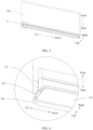
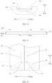
- FIG. 1 is a schematic diagram of a rotating shaft substrate 110, a bump 120, and one of support members 130 in a foldable assembly according to this embodiment. Because both two support members 130 are shown in the figure to shield most of a structure of the rotating shaft substrate 110, only one support member 130 is retained, and the two support members 130 are symmetrically distributed relative to the rotating shaft substrate 110.
- this embodiment provides the foldable assembly, including a rotating shaft mechanism and a connecting mechanism.
- the rotating shaft mechanism includes the bump 120 and the rotating shaft substrate 110.
- the bump 120 is arranged at least at an end portion of the rotating shaft substrate 110 in a length direction.
- the connecting mechanism includes two support members 130.
- the two support members 130 are respectively connected to two sides of the rotating shaft substrate 110 in a width direction, and the two support members 130 are respectively rotatable relative to the rotating shaft substrate 110, so that the foldable assembly is switched between an unfolded state and a folded state. In the unfolded state, the two support members 130 are respectively arranged on two sides of the rotating shaft substrate 110 in the width direction.
- the two support members 130 are rotated to one side of the rotating shaft substrate 110 in a thickness direction.
- a stop surface 131 is arranged on one side of the support member 130 close to the rotating shaft substrate.
- the bump 120 and the stop surface 131 are spaced apart and opposite to each other in the thickness direction of the rotating shaft substrate 110.
- bumps 120 There may be one or more bumps 120.
- the bump 120 is arranged at one end of the rotating shaft substrate 110 in the length direction.
- one bump 120 is arranged at each of two ends of the rotating shaft substrate 110 in the length direction.
- the two bumps 120 are both arranged at the same end of the rotating shaft substrate 110 in the length direction.
- the stop surface 131 may be arranged on only one support member 130, or the stop surface 131 may be arranged both on the two support members 130.
- a quantity of stop surfaces 131 is equal to a quantity of the bumps 120, and the stop surfaces are in a one-to-one correspondence to the bumps.
- one bump 120 is spaced apart and opposite to only one stop surface 131 in the thickness direction of the rotating shaft substrate 110.
- quantities of stop surfaces 131 arranged on the two support members 130 may be same or different.
- a sum of the quantities of stop surfaces 131 on the two support members 130 is greater than or equal to the quantity of the bumps 120.
- one stop surface 131 may be arranged both on the two support members 130, that is, the sum of the stop surfaces 131 is two.
- one bump 120 is respectively spaced apart and opposite to two stop surfaces 131 in the thickness direction of the rotating shaft substrate 110.
- the stop surface 131 on the support member 130 on the left side is spaced apart and opposite to a left partial region of the bump 120 in the thickness direction of the rotating shaft substrate 110
- the stop surface 131 on the support member 130 on the right side is spaced apart and opposite to a right partial region of the bump in the thickness direction of the rotating shaft substrate 110.
- the two support members 130 may both be provided with the stop surface 131, or one support member 130 is provided with the stop surface 131, and the other support member 130 is not provided with the stop surface 131.
- the bump 120 and the stop surface 131 are spaced apart and opposite to each other in the thickness direction of the rotating shaft substrate 110 to facilitate rotation of the support member 130 relative to the rotating shaft mechanism.
- a spacing between the bump 120 and a corresponding stop surface 131 ranges from 0.1 mm to 0.5 mm.
- the spacing may be 0.1 mm, 0.15 mm, 0.2 mm, 0.3 mm, 0.35 mm, 0.5 mm, or the like.
- the length direction, the width direction, and the thickness direction are all based on the length direction, the width direction, and the thickness direction of the rotating shaft substrate 110.
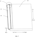
- the length direction of the rotating shaft substrate 110 is referred to as an up-down direction
- two ends of the rotating shaft substrate 110 in the length direction are respectively an upper end and a lower end.
- the two support members 130 are respectively located on left and right sides of the rotating shaft substrate 110 in the unfolded state, and a left-right direction is the width direction of the rotating shaft substrate 110.
- the thickness direction of the rotating shaft substrate 110 is referred to as a front-rear direction.
- the two support members 130 are both located on a front side of the rotating shaft substrate 110, and one side facing away from the front side is a rear side of the rotating shaft substrate 110.
- the stop surface 131 is located on a front side of the bump 120, so that the bump 120 comes into contact with the stop surface 131 after moving forward.
- the foldable assembly can be applied to a foldable display device.
- the support member 130 is configured to support a flexible screen.
- the flexible screen is laid on the two support members 130 and is supported by the two support members 130 on the front side of the rotating shaft substrate 110 in the thickness direction.
- a front side surface of the rotating shaft substrate is a support surface.
- the foldable assembly is configured to drive the flexible screen to switch between the folded state and the unfolded state.
- the bump 120 arranged on the rotating shaft substrate 110 is spaced apart and opposite to the stop surface 131 on the support member 130 in the thickness direction of the rotating shaft substrate 110.
- the rotating shaft substrate 110 drives the bump 120 to move toward the flexible screen, that is, move forward in the thickness direction of the rotating shaft substrate 110.
- the bump 120 comes into contact with the stop surface 131.
- the stop surface 131 prevents the bump 120 from continuing to move toward the flexible screen, thereby protecting the flexible screen to a certain extent.
- an impact force received by the rotating shaft mechanism is transmitted to the support member 130, so that the impact force is further dispersed through the support member 130, thereby reducing the impact force transmitted to the flexible screen, to protect the flexible screen.
- the stop surface 131 prevents the rotating shaft mechanism from continuing to move toward the flexible screen, and the impact force is dispersed and absorbed by the support member 130 to reduce the impact force that may be transmitted to the flexible screen. Therefore, a problem of damage to the flexible screen caused by the rotating shaft mechanism can be resolved to a certain extent.
- the foldable assembly provided in this embodiment may be further applied to a furniture appliance having a foldable structure, such as a refrigerator, a cabinet, or a door.
- a furniture appliance having a foldable structure, such as a refrigerator, a cabinet, or a door.
- the foldable assembly is applied to the refrigerator, one support member 130 is connected to a refrigerator body of the refrigerator, and the other support member 130 is connected to a refrigerator door.
- the foldable assembly can improve an anti-impact capability of a joint between the refrigerator door and the refrigerator body.
- the foldable assembly is applied to the cabinet, one support member 130 is connected to a cabinet body of the cabinet, and the other support member 130 is connected to a cabinet door of the cabinet.
- the foldable assembly can improve an anti-impact capability of a joint between the cabinet body and the cabinet door.
- the foldable assembly is applied to the door, one support member 130 is connected to a door frame, and the other support member 130 is connected to a door body.
- the foldable assembly can improve an anti-impact
- the support member 130 includes a support block 132, and one side surface of the support block 132 is the stop surface 131. Specifically, when the foldable assembly is in the folded state, a side surface of one side of the support block 132 facing the bump 120 is the stop surface 131.
- the support member 130 further includes a support substrate 134, and the support substrate 134 is connected to one side of the rotating shaft substrate 110 in the width direction.
- the support substrate 134 of one support member 130 is connected to a left side of the rotating shaft substrate 110
- the support substrate 134 of the other support member 130 is connected to a right side of the rotating shaft substrate 110.
- the support substrate 134 is rotatably connected to the rotating shaft substrate 110.
- the support block 132 is arranged on one side of the support substrate 134 close to the rotating shaft substrate 110.
- the support block 132 and the support substrate 134 may be an integrated structure prepared by an integrated molding and manufacturing process.
- the support block 132 and the support substrate 134 may be separate structures, and may be fixedly connected by bolting, bonding, or the like.
- the stop surface 131 is an arc-shaped surface. Still referring to FIG. 4 , the front side surface of the bump 120 may also be arranged as an arc-shaped surface. In this arrangement, a contact area between the bump 120 and the stop surface 131 can be increased. Optionally, the stop surface 131 extends toward the support substrate 134, and the stop surface 131 is finally connected to the support member 130. Through this arrangement, a transition surface between the support block 132 and the support substrate 134 is also an arc-shaped surface, that is, there is an arc transition between the support block 132 and the support substrate 134. When the bump 120 hits the support block 132, formation of a stress concentration region between the support block 132 and the support substrate 134 may be avoided.
- the front side surface of the rotating shaft substrate 110 is the support surface configured to support a to-be-supported object.
- the to-be-supported object is the flexible screen.
- the flexible screen and the support surface of the rotating shaft substrate 110 are arranged opposite to each other in the thickness direction of the rotating shaft substrate 110.
- the support surface of the rotating shaft substrate 110 may be in direct contact with the flexible screen, or another member is mounted on the support surface of the rotating shaft substrate 110 to enable the support surface to indirectly support the flexible screen.
- the rotating shaft mechanism further includes a hinge structure, and the support members 130 are rotatably connected to the rotating shaft substrate 110 through the hinge structure respectively.
- the hinge structure is mounted on the support surface of the rotating shaft substrate 110.
- the bump 120 is arranged on the support surface of the rotating shaft substrate 110, and the bump 120 protrudes forward.
- a distance between the bump 120 and an axis of the rotating shaft substrate 110 is smaller, or the bump 120 is located on a front side of a position of an axis of the rotating shaft substrate 110.
- the stop surface 131 is located on the front side of the bump 120, and the stop surface 131 and the bump 120 are spaced apart and opposite to each other in the thickness direction of the rotating shaft substrate 110.
- the stop surface 131 gradually moves away from the front side of the bump 120.
- the stop surface 131 is located on the left side or the right side of the bump 120. Specifically, if the stop surface 131 is arranged on the support member 130 on the left side, the stop surface 131 is located on the left side of the bump 120 in the unfolded state. If the stop surface 131 is arranged on the support member 130 on the right side, the stop surface 131 is located on the right side of the bump 120 in the unfolded state.
- the rotating shaft mechanism further includes a decorative member 140, and the decorative member 140 is mounted on an outer side of the rotating shaft substrate 110.
- the decorative member 140 can improve the aesthetics of a device to which the foldable assembly is applied.
- the decorative member 140 and the rotating shaft substrate 110 are made of different materials.
- the decorative member 140 covers at least the rear side of the rotating shaft substrate 110.
- the decorative member 140 may be located only on the rear side of the rotating shaft substrate 110.
- the decorative member 140 covers the left side, the rear side, and the right side of the rotating shaft substrate 110. Such an arrangement can reduce or even prevent the rotating shaft substrate 110 from exposure to an outer side of the device to which the foldable assembly is applied.
- the decorative member 140 may be used to improve the aesthetics of the rotating shaft mechanism, and the rotating shaft substrate 110 may be made of a material with stronger strength and higher rigidity without considering the aesthetics thereof.
- the rotating shaft substrate 110 is made of high-strength steel
- the decorative member 140 is made of an aluminum alloy material.
- the high-strength steel is relative to carbon structural steel, and is generally classified by using Q235 (carbon steel) as a boundary.
- Q235 carbon steel
- a low-alloy structural steel is generally referred to as the high-strength steel, that is, structural steel with the strength above Q295 is the high-strength steel.
- the rotating shaft substrate 110 is manufactured by using the high-strength steel, so that the rotating shaft substrate 110 has higher rigidity and better drop resistance.
- the bump 120 may be made of a same material as that of the rotating shaft substrate 110. Manufacturing the decorative member 140 by using the aluminum alloy material facilitates appearance shaping, and improves the aesthetics of the device to which the foldable assembly is applied.
- the decorative member 140 may be fixedly connected to the support member 130, or may be detachably connected to the support member 130.
- the decorative member 140 may be connected to the support member 130 by bolts.
- the decorative member 140 may be connected to the support member 130 by bonding, snapping, welding, or the like.
- the decorative member 140 includes an accommodating cavity 141, at least a part of a structure of the rotating shaft substrate 110 is located in the accommodating cavity 141, and at least a part of a structure of the bump 120 is located outside the accommodating cavity 141.
- the accommodating cavity 141 is provided inside the decorative member 140, so that a coverage range of the decorative member 140 for the rotating shaft substrate 110 is larger, and a thickness of an overall structure of the decorative member 140 and the rotating shaft substrate 110 is smaller.
- the decorative member 140 is provided with the accommodating cavity 141 on the front side surface, and an opening of the accommodating cavity 141 is located on a front side of the accommodating cavity 141.
- the rotating shaft substrate 110 is placed into the accommodating cavity 141 from front to back, so that the rotating shaft substrate 110 is completely located in the accommodating cavity 141, and the bump 120 extends out of the opening of the accommodating cavity 141.
- the rotating shaft substrate 110 may be a plate-shaped structure, and the bump 120 is mounted on a front side of the plate-shaped structure.
- the rotating shaft substrate 110 includes a main body 111 and a connecting body 112, the connecting body 112 is arranged at an end portion of the main body 111 in the length direction, and the bump 120 is arranged on the connecting body 112.
- the connecting body 112 there is one connecting body 112 and the connecting body is arranged at one end of the main body 111 in the length direction.
- Only one bump 120 may be arranged on the connecting body 112, or two bumps 120 may be spaced apart on the connecting body. The two bumps 120 are spaced apart in the width direction of the connecting body 112.
- each connecting body 112 is provided with one bump 120, that is, a total quantity of bumps 120 on the rotating shaft substrate 110 is two.
- each connecting body 112 is provided with two bumps 120, that is, a total quantity of bumps 120 on the rotating shaft substrate 110 is four.
- connecting bodies 112 are respectively arranged at two ends of the main body 111 in the length direction, one bump 120 is arranged on each of two connecting bodies 112, and a thickness of the connecting body 112 is greater than a thickness of the main body 111. Because the bump 120 is connected to the connecting body 112, and a relative thickness of the connecting body 112 is thicker, the rotating shaft substrate 110 has stronger structural rigidity and stronger impact resistance at a position in which the bump 120 is arranged.
- the main body 111 has a strip-shaped plate-like structure, the connecting bodies 112 are respectively arranged at an upper end and a lower end of the main body 111, and the bumps 120 are respectively arranged on the two connecting bodies 112.
- a length of the connecting body 112 in the width direction is less than a length of the main body 111 in the width direction, or a length of the connecting body 112 in the left-right direction is less than a length of the main body 111 in the left-right direction.
- a length of the bump 120 in the width direction is less than a length of the connecting body 112 in the width direction, or a length of the bump 120 in the left-right direction is less than a length of the connecting body 112 in the left-right direction.
- the upper end and the lower end of the main body 111 are respectively provided with the connecting body 112, and the bump 120 protrudes forward from the support surface of the connecting body 112.
- a horizontal plane on which the front side surface of the bump 120 is located is located above a horizontal plane on which the front side surface of the main body 111 is located, and a horizontal plane on which a rear side surface of the connecting body 112 is located is located below a horizontal plane on which the rear side surface of the main body 111 is located.
- an end portion of the decorative member 140 in the length direction of the rotating shaft substrate 110 is provided with a bracket 142.
- the connecting body 112 is limited in the bracket 142, and the bracket 142 plays a certain role in limiting the connecting body 112.
- the bump 120 protrudes to an outer side of the bracket 142 in the thickness direction of the rotating shaft substrate 110, that is, the front side surface of the bump 120 is located outside the bracket 142.
- the bump 120 protrudes to the outer side of the bracket 142 in the thickness direction of the rotating shaft substrate 110.
- the connecting body 112 having a larger thickness is placed in the bracket 142, so that a thickness of an overall structure of the decorative member 140 and the rotating shaft substrate 110 is smaller, which is convenient for being applied to the foldable display device having a smaller thickness, and a length of the overall structure of the decorative member 140 and the rotating shaft substrate 110 is also smaller.
- one bracket 142 is provided at each of a front end and a rear end of the decorative member 140, and the accommodating cavity 141 is located between two brackets 142.
- the decorative member 140 may be provided with only the accommodating cavity 141 and not with the bracket 142, or may be provided with only the bracket 142 and not with the accommodating cavity 141.
- the decorative member 140 is provided with both the accommodating cavity 141 and the bracket 142.
- the decorative member 140 is provided with a separating plate 143, and the separating plate 143 separates the bracket 142 from the accommodating cavity 141.
- the main body 111 is located between two separating plates 143, and the separating plates 143 support two ends of the main body 111 in the length direction.
- the decorative member with two brackets 142 shown in FIG. 13 is adapted to the rotating shaft substrate 110 with two connecting bodies 112 (the rotating shaft substrate 110 is shown in FIG. 11 ).
- FIG. 14 shows a relative positional relationship between a support member and a rotating shaft mechanism in the folded state.
- a direction perpendicular to a paper surface is a length direction of the rotating shaft substrate 110.
- Only a relative positional relationship between the bump 120 arranged at a lower end of the rotating shaft substrate 110 and the stop surface 131 of the support member 130 is shown in FIG. 14 .
- two stop surfaces 131 are arranged on each of the two support members 130, and one bump 120 is arranged on each of two ends of the rotating shaft substrate 110 in the length direction, that is, a total of two bumps 120 are arranged on the rotating shaft substrate 110.
- FIG. 14 shows the bump 120 arranged at the lower end of the rotating shaft substrate 110.
- a left region of the front side surface of the bump 120 located at the lower end of the rotating shaft substrate 110 and the stop surface 131 of the support member 130 on a left side are spaced apart and opposite to each other in the thickness direction of the rotating shaft substrate 110
- a right region of the front side surface of the bump 120 and the stop surface 131 of the support member 130 on a right side are spaced apart and opposite to each other in the thickness direction of the rotating shaft substrate 110.
- a left region of the front side surface of the bump 120 located on an upper end of the rotating shaft substrate 110 and the stop surface 131 of the support member 130 on the left side are spaced apart and opposite to each other in the thickness direction of the rotating shaft substrate 110, and a right region of the front side surface of the bump 120 and the stop surface 131 of the support member 130 on the right side are spaced apart and opposite to each other in the thickness direction of the rotating shaft substrate 110.
- the two support members 130 have the same structure and are symmetrically arranged relative to the rotating shaft substrate 110.
- One stop surface 131 is arranged at the upper end and the lower end of each of the two support members 130, that is, two stop surfaces 131 are arranged on each support member 130, and a quantity of stop surfaces 131 on the two support members 130 is four.
- One bump 120 is arranged at both the upper end and the lower end of the rotating shaft substrate 110. That is, the stop surfaces 131 at the upper ends of the two support members 130 are spaced apart and opposite to the same bump 120 at the upper end of the rotating shaft substrate 110, and the stop surfaces 131 at the lower ends of the two support members 130 are spaced apart and opposite to the same bump 120 at the lower end of the rotating shaft substrate 110 in the thickness direction of the rotating shaft substrate 110.
- one bump 120 needs to be opposite to two stop surfaces 131, a width of the bump 120 is longer. After the rotating shaft mechanism is hit, one bump 120 can come into contact with two stop surfaces 131 to transmit the impact force to the two support members 130 through the two stop surfaces 131 respectively.
- the support blocks 132 are arranged at the upper end and the lower end of the two support members 130, and the stop surfaces 131 are formed on the support blocks 132.
- FIG. 15 shows another relative positional relationship between a support member and a rotating shaft mechanism in the folded state.
- a direction perpendicular to a paper surface is a length direction of the rotating shaft substrate 110.
- Only a relative positional relationship between the bump 120 arranged at the lower end of the rotating shaft substrate 110 and the stop surface 131 of the support member 130 is shown in FIG. 15 .
- one stop surface 131 is arranged on each of the two support members 130, and one bump 120 is arranged on each of two ends of the rotating shaft substrate 110. That is, two bumps 120 are arranged on the rotating shaft substrate 110, and a total of two stop surfaces 131 are arranged on the two support members 130.
- one stop surface 131 is arranged at one end of one support member 130 in the length direction of the rotating shaft substrate 110, and one stop surface 131 is arranged at an other end of the other support member 130 in the length direction of the rotating shaft substrate 110.
- one bump 120 is spaced apart and opposite to the stop surface 131 of one support member 130, and the other bump 120 is spaced apart and opposite to the stop surface 131 of the other support member 130.
- one end shown in FIG. 15 is used as the lower end, the lower end of the support member 130 on the left is not provided with the stop surface 131, and the lower end of the support member 130 on the right is provided with the stop surface 131.
- one support member 130 is provided with only one stop surface 131, the upper end of the support member 130 on the left is provided with the stop surface 131, and the upper end of the support member 130 on the right is not provided with the stop surface 131.
- the bump 120 is arranged on a left side of the upper end of the rotating shaft substrate 110, and the bump 120 is arranged on a right side of the lower end of the rotating shaft substrate 110.
- the rotating shaft mechanism When a lower end of the rotating shaft mechanism is hit, the rotating shaft mechanism implements a stop operation through the support member 130 on the right side, and disperses the impact force through the support member 130 on the right side.
- the bump 120 on the upper end and the lower end of the rotating shaft substrate 110 is only configured to be opposite to the stop surface 131 on one of the support members 130, a width of the bump 120 is smaller, that is, an overall weight of the rotating shaft mechanism is smaller.
- FIG. 16 shows a relative positional relationship between a support member and a rotating shaft mechanism in the folded state.
- a direction perpendicular to a paper surface is a length direction of the rotating shaft substrate 110.
- Only a relative positional relationship between the bump 120 arranged at a lower end of the rotating shaft substrate 110 and the stop surface 131 of the support member 130 is shown in FIG. 16 .
- at least one end of the rotating shaft substrate 110 in the length direction is provided with two bumps 120, and the two bumps 120 are spaced apart in the width direction of the rotating shaft substrate 110.
- one bump 120 and one stop surface 131 of one support member 130 are spaced apart and opposite to each other in the thickness direction of the rotating shaft substrate 110, and the other bump 120 and the stop surface 131 of the other support member 130 are spaced apart and opposite to each other in the thickness direction of the rotating shaft substrate 110.
- an arrangement position of the stop surface 131 may be selected based on a structural arrangement requirement of the support member 130, and a position of the bump 120 matching the stop surface 131 on the rotating shaft substrate 110 is arranged based on the arrangement position of the stop surface 131.
- FIG. 17 shows a relative positional relationship between a support member and a rotating shaft mechanism in the folded state.
- a direction perpendicular to a paper surface is a length direction of the rotating shaft substrate 110.
- the bump 120 is arranged on the side surface of the rotating shaft substrate 110 in the width direction and extends in the width direction.
- the bump 120 may be arranged on a left side surface and/or a right side surface of the rotating shaft substrate 110.
- an end portion of a left side surface and an end portion of a right side surface of the rotating shaft substrate 110 are both provided with the bump 120, the bump 120 on the left side surface extends to the left, and the bump 120 on the right side surface extends to the right.
- the support member 130 on the left side is provided with a groove 133 with a rightward opening, and the support member 130 on the right side is provided with a slot with a leftward opening.
- the state shown in FIG. 17 is the folded state. In the folded state, the bump 120 on the left side is located in the groove 133 of the support member 130 on the left side, and the bump 120 on the right side is located in the groove 133 of the support member 130 on the right side.
- a buffer structure is arranged on the stop surface 131 and/or the bump 120. In the folded state, the buffer structure is located between the stop surface 131 and the bump 120.
- the impact force transmitted by the bump 120 to the stop surface 131 may be buffered to a certain extent by using the buffer structure, thereby reducing the impact force received by the support member 130 provided with the stop surface 131, and improving the anti-impact capability of the foldable assembly.
- the buffer structure may further absorb the impact force through characteristics such as elastic deformation and collapse deformation of the buffer structure, to reduce the impact force transmitted from the rotating shaft mechanism to the support member 130.
- the buffer structure includes a flexible buffer pad 151.
- the flexible buffer pad 151 deforms under extrusion of the bump 120 and the stop surface 131 during movement of the bump 120 toward the stop surface 131, thereby absorbing part of the impact force.
- the flexible buffer pad 151 is arranged on the front side surface of the bump 120.
- the flexible buffer pad 151 may be arranged on the stop surface 131.
- a connection manner between the flexible buffer pad 151 and the bump 120 or the stop surface 131 may be bonding.
- the flexible buffer pad 151 may be a sheet-shaped structure made of a material such as sponge, silicone, or rubber.
- the buffer structure is mounted on the bump 120.
- the buffer structure includes a buffer plate 152 and an elastomer 153.
- the buffer plate 152 and the bump 120 are spaced apart and opposite to each other in the thickness direction of the rotating shaft substrate 110.
- the elastomer 153 is located between the buffer plate 152 and the bump 120, and the elastomer 153 is connected to the buffer plate 152 and the bump 120 respectively.
- the buffer plate 152 and the stop surface 131 are spaced apart and opposite to each other in the thickness direction of the rotating shaft substrate 110.
- the arrangement of the buffer plate 152 can increase a contact area with the stop surface 131, and the elastomer 153 can compress and deform to absorb part of the impact force.
- the elastomer 153 may push the rotating shaft substrate 110 to move away from the flexible screen through elasticity of the elastomer 153, so that the rotating shaft substrate 110 can be reset.
- the elastomer 153 is specifically a spring, and a plurality of springs are arranged between the buffer plate 152 and the bump 120.
- the elastomer 153 may alternatively be another elastic structure such as a rubber column or an elastic sheet.
- This embodiment further provides a foldable display device, including: a flexible screen and the foldable assembly provided in any one of the foregoing embodiments.
- the flexible screen is laid on two support members 130 in the foldable assembly and covers the support surface of the rotating shaft substrate 110.
- the bump 120 may be located on two sides of the flexible screen in the length direction of the rotating shaft substrate 110.
- at least one bump 120 is located on one side of the flexible screen in the length direction of the rotating shaft substrate 110, and at least one bump 120 is located on the other side of the flexible screen in the length direction of the rotating shaft substrate 110.
- the bumps 120 and the flexible screen are not opposite to each other in the front-rear direction, or are alternately distributed. When the rotating shaft mechanism is hit, the bump 120 does not squeeze the flexible screen after moving forward.
- the foldable display device provided in this embodiment includes the foregoing foldable assembly
- the stop surface 131 in the foldable mechanism prevents the rotating shaft mechanism from continuing to move toward the flexible screen, and the impact force is dispersed and absorbed by the support member 130, to reduce the impact force that may be transmitted to the flexible screen. Therefore, the problem of damage to the flexible screen caused by the rotating shaft mechanism can be resolved to a certain extent.
- the foldable display device includes, but is not limited to, a foldable electronic device having a flexible display screen such as a mobile phone, a tablet computer, an electric paper book, and a smartwatch.
- the two support members 130 may be respectively two side housings of the mobile phone, the housing includes a middle frame, and the support member may be specifically the middle frame in the housing.
- the support member 130 is independent of the housing, and two support members 130 may be respectively connected to two middle frames in the mobile phone in a one-to-one correspondence.
Landscapes
- Engineering & Computer Science (AREA)
- General Engineering & Computer Science (AREA)
- Theoretical Computer Science (AREA)
- Physics & Mathematics (AREA)
- Computer Hardware Design (AREA)
- General Physics & Mathematics (AREA)
- Human Computer Interaction (AREA)
- Mechanical Engineering (AREA)
- Microelectronics & Electronic Packaging (AREA)
- Signal Processing (AREA)
- Acoustics & Sound (AREA)
- Aviation & Aerospace Engineering (AREA)
- Mathematical Physics (AREA)
- Chemical & Material Sciences (AREA)
- Combustion & Propulsion (AREA)
- Devices For Indicating Variable Information By Combining Individual Elements (AREA)
- Pivots And Pivotal Connections (AREA)
Abstract
Description
- This application claims priority to
Chinese Patent Application No. 202210768377.6, filed with the China National Intellectual Property Administration on July 1, 2022 - This application relates to the field of foldable device technologies, and in particular, to a foldable assembly and a foldable display device.
- With the development of display technologies, a foldable display device is increasingly favored by users because the foldable display device can obtain a larger display area in an unfolded state and better portability in a folded state. The foldable display device includes a flexible screen, a rotating shaft, and two housings. The two housings are rotatably connected by the rotating shaft, and the flexible screen is laid on the two housings. The two housings are swung in opposite directions, so that unfolding and folding operations of the foldable display device can be implemented. When the foldable display device is in the folded state, the two housings flip to the same side of the rotating shaft, that is, the rotating shaft is located on one side edge of the foldable display device. In the folded state, if the foldable display device falls off, the foldable display device is likely to be in an oblique downward falling state during falling. As a result, a corner of the foldable display device is first hit. Because the rotating shaft is located on one side edge of the foldable display device, one end of the rotating shaft is likely to be first hit, resulting in inward collapse of the rotating shaft, which squeezes the flexible screen and causes damage to the flexible screen.
- To resolve the foregoing problems, at present, there are generally two solutions. One solution is to arrange a thicker rotating shaft, so that the rotating shaft has stronger impact resistance. However, in this solution, a weight of an entire machine is larger, and to match a size of the rotating shaft, a thickness of the entire machine is increased, leading to poor portability and a decrease in the use experience. Another solution is to arrange a rounded corner at one end of the rotating shaft, and the rounded corner on a side on which the housing is connected to the rotating shaft is enlarged, so that the housing is hit before the rotating shaft or the housing and the rotating shaft are hit simultaneously after the foldable display device falls off, to share an impact force on the rotating shaft through the housing. However, in this arrangement, angles of the rounded corners on the two sides of the housing are different, resulting in an inconsistent ratio of two sides of the foldable display device in the folded state and reduced use experience.
- It can be learned from the above that, at present, a problem of damage to the flexible screen caused by the inward collapse of the rotating shaft after being hit cannot be resolved without changing the appearance of the foldable display device.
- This application provides a foldable assembly and a foldable display device. Both the foldable assembly and the foldable display device can resolve a problem of damage to a flexible screen caused by inward collapse of a rotating shaft under impact to a certain extent.
- The technical solutions are as follows:
- According to a first aspect, this application provides a foldable assembly, including: a rotating shaft mechanism and a connecting mechanism, where
- the rotating shaft mechanism comprises a bump and a rotating shaft substrate, and the bump is arranged at an end portion of the rotating shaft substrate in a length direction;
- the connecting mechanism comprises two support members, the two support members are respectively connected to two sides of the rotating shaft substrate in a width direction, and the two support members are respectively rotatable relative to the rotating shaft substrate, so that the foldable assembly is switched between an unfolded state and a folded state; and
- a stop surface is arranged on one side of the support member close to the rotating shaft substrate, and in the folded state, the bump and the stop surface are spaced apart and opposite to each other in a thickness direction of the rotating shaft substrate.
- The foldable assembly provided in this application can be applied to a foldable display device. When the foldable assembly is applied to the foldable display device, a to-be-supported object is a flexible screen in the foldable display device, that is, a support member is configured to support the flexible screen. The foldable assembly is configured to drive the flexible screen to switch between the folded state and the unfolded state. In the folded state, the bump arranged on the rotating shaft substrate is spaced apart and opposite to the stop surface on the support member. If the foldable display device falls off in the folded state, after the rotating shaft mechanism is hit, the rotating shaft substrate drives the bump to move in a direction close to the flexible screen, that is, move forward in the thickness direction of the rotating shaft substrate. After the bump moves by a certain distance, the bump comes into contact with the stop surface. According to an aspect, the stop surface prevents the bump from continuing to move toward the flexible screen, thereby protecting the flexible screen. According to another aspect, an impact force received by the rotating shaft mechanism is transmitted to the support member through contact between the bump and the stop surface, so that the impact force is further dispersed by the support member, thereby reducing the impact force transmitted to the flexible screen, to protect the flexible screen.
- When the foldable display device falls off and the rotating shaft mechanism is first hit, the stop surface prevents the rotating shaft mechanism from continuing to move toward the flexible screen, and the impact force is dispersed and absorbed by the support member to reduce the impact force that may be transmitted to the flexible screen. Therefore, a problem of damage to the flexible screen caused by the rotating shaft mechanism can be resolved to a certain extent.
- In some implementations, the support member includes a support substrate and a support block, the support substrate is connected to one side of the rotating shaft substrate in the width direction, and the support substrate is rotatable relative to the rotating shaft substrate. The support block is arranged on the support substrate, the support block is arranged on one side of the support substrate close to the rotating shaft substrate, and one side surface of the support block is the stop surface.
- In some implementations, the rotating shaft substrate includes a support surface, the support surface is configured to support a to-be-supported object, and the bump is arranged on the support surface of the rotating shaft substrate.
- In some implementations, one bump is arranged at two ends of the rotating shaft substrate in the length direction respectively, the stop surface is arranged at two ends of each of the support members in the length direction, and in the folded state, each bump and the stop surfaces of the two support members are spaced apart and opposite to each other in the thickness direction of the rotating shaft substrate.
- In some implementations, two ends of the rotating shaft substrate in the length direction are respectively provided one of the bumps, one of the two support members is provided with one of the stop surfaces at one end of the rotating shaft substrate in the length direction, and an other of the two support members is provided with one of the stop surfaces at an other end of the rotating shaft substrate in the length direction; and in the folded state, one of the bumps and the stop surface of one of the support members are spaced apart and opposite to each other in the thickness direction of the rotating shaft substrate, and the other of the bumps and the stop surface of the other of the support members are spaced apart and opposite to each other in the thickness direction of the rotating shaft substrate.
- In some implementations, two bumps are arranged at at least one end of the rotating shaft substrate in the length direction, the two bumps are spaced apart in the width direction of the rotating shaft substrate, and the stop surface is arranged at end portions of the two support members corresponding to the bumps in the length direction of the rotating shaft substrate; and in the folded state, one of the bumps and the stop surface of one of the support members are spaced apart and opposite to each other in the thickness direction of the rotating shaft substrate, and the other of the bumps and the stop surface of the other of the support members are spaced apart and opposite to each other in the thickness direction of the rotating shaft substrate.
- In some implementations, the bump is arranged on a side surface of the rotating shaft substrate in the width direction, the support member is provided with a groove, and an inner wall of one side of the groove forms the stop surface; and in the folded state, the bump is located in the groove and is spaced apart and opposite to the stop surface in the thickness direction of the rotating shaft substrate.
- In this arrangement, because the bump is arranged on the side surface of the rotating shaft substrate in the width direction, the arrangement of the bump does not increase a thickness of the rotating shaft mechanism, so that the thickness of the rotating shaft mechanism is smaller.
- In some implementations, the rotating shaft mechanism further comprises a decorative member, and the decorative member is mounted on an outer side of the rotating shaft substrate.
- In this arrangement, because the decorative member is mounted on the outer side of the rotating shaft substrate, the decorative member can be used to improve aesthetics of the rotating shaft mechanism.
- In some implementations, the decorative member comprises an accommodating cavity, at least a part of a structure of the rotating shaft substrate is located in the accommodating cavity, and at least a part of a structure of the bump is located outside the accommodating cavity.
- In this arrangement, the accommodating cavity is arranged inside the decorative member, so that a coverage range of the decorative member for the rotating shaft substrate is larger, and a thickness of an overall structure of the decorative member and the rotating shaft substrate is smaller.
- In some implementations, the rotating shaft substrate comprises a main body and a connecting body, an end portion of the main body in the length direction is provided with the connecting body, the bump is arranged on the connecting body, and a thickness of the connecting body is greater than a thickness of the main body.
- Because the bump is connected to the connecting body, and a relative thickness of the connecting body is thicker, the structural rigidity of the rotating shaft substrate is stronger at a position in which the bump is arranged, and the impact resistance is stronger.
- In some implementations, a bracket is provided at an end portion of the decorative member in the length direction of the rotating shaft substrate, the connecting body is limited in the bracket, and the bump protrudes from the bracket in the thickness direction of the rotating shaft substrate.
- In this arrangement, according to an aspect, the connecting body is limited by the bracket, and according to another aspect, the connecting body with a larger thickness is placed in the bracket, so that an overall structure of the decorative member and the rotating shaft substrate has a smaller thickness, which is convenient to be applied to a foldable display device with a smaller thickness.
- In some implementations, a buffer structure is arranged on the stop surface and/or the bump, and in the folded state, the buffer structure is located between the stop surface and the bump.
- Through the foregoing arrangement, the impact force transmitted by the bump to the stop surface may be buffered to a certain extent by using the buffer structure, thereby reducing the impact force received by the support member provided with the stop surface, and improving an anti-impact capability of the foldable assembly.
- In some implementations, the buffer structure includes a flexible buffer pad.
- Through its own flexible characteristic, the flexible buffer pad deforms under extrusion of the bump and the stop surface during movement of the bump toward the stop surface, thereby absorbing part of the impact force.
- In some implementations, the buffer structure is mounted on the bump, the buffer structure includes a buffer plate and an elastomer, the buffer plate and the bump are spaced apart and opposite to each other in the thickness direction of the rotating shaft substrate, the elastomer is located between the buffer plate and the bump, and the elastomer is connected to the buffer plate and the bump respectively, and in the folded state, the buffer plate and the stop surface are spaced apart and opposite to each other in the thickness direction of the rotating shaft substrate.
- Through the foregoing arrangement, during the movement of the bump toward the stop surface, the buffer plate first comes into contact with the stop surface. The arrangement of the buffer plate can increase a contact area with the stop surface, and the elastomer can compress and deform to absorb part of the impact force. In addition, after the impact ends, the elastomer may push the rotating shaft substrate to move away from the flexible screen through elasticity of the elastomer, so that the rotating shaft substrate can be reset.
- According to a second aspect, this application provides a foldable display device, including: a flexible screen and the foldable assembly provided in any one of the foregoing implementations, where the flexible screen is laid on two support members in the foldable assembly and covers the support surface of the rotating shaft substrate.
- The foldable display device provided in this application includes the foregoing foldable assembly. Therefore, when the foldable display device falls off in the folded state, if the rotating shaft mechanism is first hit, the stop surface in the foldable mechanism prevents the rotating shaft mechanism from continuing to move toward the flexible screen, and the impact force is dispersed and absorbed by the support member, to reduce the impact force that may be transmitted to the flexible screen. Therefore, the problem of damage to the flexible screen caused by the rotating shaft mechanism can be resolved to a certain extent.
-
-
FIG. 1 is a schematic exploded view of a rotating shaft mechanism and a support member in a foldable assembly according to an embodiment of this application; -
FIG. 2 is an enlarged view at A inFIG. 1 ; -
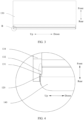
FIG. 3 is a schematic structural diagram of a support member and a rotating shaft mechanism in a folded state in a foldable assembly from one perspective according to an embodiment of this application; -
FIG. 4 is an enlarged view at B inFIG. 3 ; -
FIG. 5 is a schematic structural diagram of a support member and a rotating shaft mechanism in a folded state in a foldable assembly from another perspective according to an embodiment of this application; -
FIG. 6 is an enlarged view at C inFIG. 5 ; -
FIG. 7 is a schematic structural diagram of a support member and a rotating shaft mechanism in an unfolded state in a foldable assembly according to an embodiment of this application; -
FIG. 8 is an enlarged view at D inFIG. 7 ; -
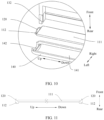
FIG. 9 is a schematic exploded view of another rotating shaft mechanism and a support member in a foldable assembly according to an embodiment of this application; -
FIG. 10 is an enlarged view at E inFIG. 9 ; -
FIG. 11 is a schematic structural diagram of a rotating shaft substrate and a bump in a foldable assembly according to an embodiment of this application; -
FIG. 12 is a schematic structural diagram of a decorative member in a foldable assembly from one perspective according to an embodiment of this application; -
FIG. 13 is a schematic structural diagram of a decorative member in a foldable assembly from another perspective according to an embodiment of this application; -
FIG. 14 is a schematic structural diagram of two support members and a rotating shaft mechanism in a folded state in a first foldable assembly according to an embodiment of this application; -
FIG. 15 is a schematic structural diagram of two support members and a rotating shaft mechanism in a folded state in a second foldable assembly according to an embodiment of this application; -
FIG. 16 is a schematic structural diagram of two support members and a rotating shaft mechanism in a folded state in a third foldable assembly according to an embodiment of this application; -
FIG. 17 is a schematic structural diagram of two support members and a rotating shaft mechanism in a folded state in a fourth foldable assembly according to an embodiment of this application; -
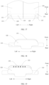
FIG. 18 is a schematic diagram of assembly of a buffer structure and a bump in a foldable assembly according to an embodiment of this application; and -
FIG. 19 is a schematic diagram of assembly of another buffer structure and a bump in a foldable assembly according to an embodiment of this application. - The meanings represented by reference numerals are as follows:
110. Rotating shaft substrate; 111. Main body; 112. Connecting body; 120. Bump; 130. Support member; 131. Stop surface; 132. Support block; 133. Groove; 134. Support substrate; 140. Decorative member; 141. Accommodating cavity; 142. Bracket; 143. Separating plate; 151. Flexible buffer pad; 152. Buffer plate; 153. Elastomer. - To make objectives, technical solutions, and advantages of this application clearer, implementations of this application are further described below in detail with reference to the accompanying drawings.
- It is to be understood that "plurality of' mentioned in this application refers to two or more. In the descriptions of this application, "/" represents "or" unless otherwise specified. For example, A/B may represent A or B. In this specification, "and/or" describes only an association relationship for describing associated objects and represents that three relationships may exist. For example, A and/or B may represent the following three cases: Only A exists, both A and B exist, and only B exists. In addition, for ease of describing the technical solutions in this application clearly, terms such as "first" and "second" are used to distinguish same or similar items having basically same functions and roles. A person skilled in the art may understand that the terms, such as "first" and "second", do not limit a quantity or an execution sequence, and the terms, such as "first" and "second", do not indicate a definite difference.
- A foldable assembly and a foldable display device provided in embodiments of this application are described in detail below. In the accompanying drawings of this application, all leads with arrows point to a surface of a device, and all leads with dots point to a device or a region.
-
FIG. 1 is a schematic diagram of arotating shaft substrate 110, abump 120, and one ofsupport members 130 in a foldable assembly according to this embodiment. Because both twosupport members 130 are shown in the figure to shield most of a structure of therotating shaft substrate 110, only onesupport member 130 is retained, and the twosupport members 130 are symmetrically distributed relative to therotating shaft substrate 110. - As shown in
FIG. 1 and FIG. 2 , this embodiment provides the foldable assembly, including a rotating shaft mechanism and a connecting mechanism. The rotating shaft mechanism includes thebump 120 and therotating shaft substrate 110. Thebump 120 is arranged at least at an end portion of therotating shaft substrate 110 in a length direction. The connecting mechanism includes twosupport members 130. The twosupport members 130 are respectively connected to two sides of therotating shaft substrate 110 in a width direction, and the twosupport members 130 are respectively rotatable relative to therotating shaft substrate 110, so that the foldable assembly is switched between an unfolded state and a folded state. In the unfolded state, the twosupport members 130 are respectively arranged on two sides of therotating shaft substrate 110 in the width direction. In the folded state, the twosupport members 130 are rotated to one side of therotating shaft substrate 110 in a thickness direction. Astop surface 131 is arranged on one side of thesupport member 130 close to the rotating shaft substrate. In the folded state, thebump 120 and thestop surface 131 are spaced apart and opposite to each other in the thickness direction of therotating shaft substrate 110. - There may be one or
more bumps 120. When there is onebump 120, thebump 120 is arranged at one end of therotating shaft substrate 110 in the length direction. When there are twobumps 120, onebump 120 is arranged at each of two ends of therotating shaft substrate 110 in the length direction. Alternatively, the twobumps 120 are both arranged at the same end of therotating shaft substrate 110 in the length direction. - In the two
support members 130, thestop surface 131 may be arranged on only onesupport member 130, or thestop surface 131 may be arranged both on the twosupport members 130. When thestop surface 131 is arranged on only onesupport member 130, a quantity of stop surfaces 131 is equal to a quantity of thebumps 120, and the stop surfaces are in a one-to-one correspondence to the bumps. In other words, in the folded state, onebump 120 is spaced apart and opposite to only onestop surface 131 in the thickness direction of therotating shaft substrate 110. When thestop surface 131 is arranged both on the twosupport members 130, quantities of stop surfaces 131 arranged on the twosupport members 130 may be same or different. A sum of the quantities of stop surfaces 131 on the twosupport members 130 is greater than or equal to the quantity of thebumps 120. For example, when there is onebump 120, onestop surface 131 may be arranged both on the twosupport members 130, that is, the sum of the stop surfaces 131 is two. In the folded state, onebump 120 is respectively spaced apart and opposite to two stopsurfaces 131 in the thickness direction of therotating shaft substrate 110. If the twosupport members 130 are respectively mounted on left and right sides of therotating shaft substrate 110, in the folded state, thestop surface 131 on thesupport member 130 on the left side is spaced apart and opposite to a left partial region of thebump 120 in the thickness direction of therotating shaft substrate 110, and thestop surface 131 on thesupport member 130 on the right side is spaced apart and opposite to a right partial region of the bump in the thickness direction of therotating shaft substrate 110. - In other words, the two
support members 130 may both be provided with thestop surface 131, or onesupport member 130 is provided with thestop surface 131, and theother support member 130 is not provided with thestop surface 131. Thebump 120 and thestop surface 131 are spaced apart and opposite to each other in the thickness direction of therotating shaft substrate 110 to facilitate rotation of thesupport member 130 relative to the rotating shaft mechanism. In the folded state, a spacing between thebump 120 and acorresponding stop surface 131 ranges from 0.1 mm to 0.5 mm. For example, the spacing may be 0.1 mm, 0.15 mm, 0.2 mm, 0.3 mm, 0.35 mm, 0.5 mm, or the like. - For each structure described in this embodiment, the length direction, the width direction, and the thickness direction are all based on the length direction, the width direction, and the thickness direction of the
rotating shaft substrate 110. As shown inFIG. 2 , the length direction of therotating shaft substrate 110 is referred to as an up-down direction, and two ends of therotating shaft substrate 110 in the length direction are respectively an upper end and a lower end. The twosupport members 130 are respectively located on left and right sides of therotating shaft substrate 110 in the unfolded state, and a left-right direction is the width direction of therotating shaft substrate 110. The thickness direction of therotating shaft substrate 110 is referred to as a front-rear direction. In the folded state, the twosupport members 130 are both located on a front side of therotating shaft substrate 110, and one side facing away from the front side is a rear side of therotating shaft substrate 110. In the folded state, thestop surface 131 is located on a front side of thebump 120, so that thebump 120 comes into contact with thestop surface 131 after moving forward. - The foldable assembly can be applied to a foldable display device. When the foldable assembly is applied to the foldable display device, the
support member 130 is configured to support a flexible screen. The flexible screen is laid on the twosupport members 130 and is supported by the twosupport members 130 on the front side of therotating shaft substrate 110 in the thickness direction. A front side surface of the rotating shaft substrate is a support surface. The foldable assembly is configured to drive the flexible screen to switch between the folded state and the unfolded state. In the folded state, thebump 120 arranged on therotating shaft substrate 110 is spaced apart and opposite to thestop surface 131 on thesupport member 130 in the thickness direction of therotating shaft substrate 110. If the foldable display device falls off in the folded state, after the rotating shaft mechanism is hit, therotating shaft substrate 110 drives thebump 120 to move toward the flexible screen, that is, move forward in the thickness direction of therotating shaft substrate 110. After thebump 120 moves by a certain distance, thebump 120 comes into contact with thestop surface 131. On one hand, thestop surface 131 prevents thebump 120 from continuing to move toward the flexible screen, thereby protecting the flexible screen to a certain extent. On the other hand, through contact between thebump 120 and thestop surface 131, an impact force received by the rotating shaft mechanism is transmitted to thesupport member 130, so that the impact force is further dispersed through thesupport member 130, thereby reducing the impact force transmitted to the flexible screen, to protect the flexible screen. - When the foldable display device falls off and the rotating shaft mechanism is first hit, the
stop surface 131 prevents the rotating shaft mechanism from continuing to move toward the flexible screen, and the impact force is dispersed and absorbed by thesupport member 130 to reduce the impact force that may be transmitted to the flexible screen. Therefore, a problem of damage to the flexible screen caused by the rotating shaft mechanism can be resolved to a certain extent. - In addition, in addition to being applied to the foldable display device, the foldable assembly provided in this embodiment may be further applied to a furniture appliance having a foldable structure, such as a refrigerator, a cabinet, or a door. When the foldable assembly is applied to the refrigerator, one
support member 130 is connected to a refrigerator body of the refrigerator, and theother support member 130 is connected to a refrigerator door. The foldable assembly can improve an anti-impact capability of a joint between the refrigerator door and the refrigerator body. When the foldable assembly is applied to the cabinet, onesupport member 130 is connected to a cabinet body of the cabinet, and theother support member 130 is connected to a cabinet door of the cabinet. The foldable assembly can improve an anti-impact capability of a joint between the cabinet body and the cabinet door. When the foldable assembly is applied to the door, onesupport member 130 is connected to a door frame, and theother support member 130 is connected to a door body. The foldable assembly can improve an anti-impact capability of a joint between the door body and the door frame. - Further descriptions are provided below by using an example in which the foldable assembly is applied to the foldable display device.
- As shown in
FIG. 2 to FIG. 4 , in a specific implementation, thesupport member 130 includes asupport block 132, and one side surface of thesupport block 132 is thestop surface 131. Specifically, when the foldable assembly is in the folded state, a side surface of one side of thesupport block 132 facing thebump 120 is thestop surface 131. - As shown in
FIG. 4 , thesupport member 130 further includes asupport substrate 134, and thesupport substrate 134 is connected to one side of therotating shaft substrate 110 in the width direction. For example, in the twosupport members 130, thesupport substrate 134 of onesupport member 130 is connected to a left side of therotating shaft substrate 110, and thesupport substrate 134 of theother support member 130 is connected to a right side of therotating shaft substrate 110. Thesupport substrate 134 is rotatably connected to therotating shaft substrate 110. Thesupport block 132 is arranged on one side of thesupport substrate 134 close to therotating shaft substrate 110. In a feasible arrangement, thesupport block 132 and thesupport substrate 134 may be an integrated structure prepared by an integrated molding and manufacturing process. Certainly, in another arrangement, thesupport block 132 and thesupport substrate 134 may be separate structures, and may be fixedly connected by bolting, bonding, or the like. - As shown in
FIG. 4 , in a feasible arrangement, thestop surface 131 is an arc-shaped surface. Still referring toFIG. 4 , the front side surface of thebump 120 may also be arranged as an arc-shaped surface. In this arrangement, a contact area between thebump 120 and thestop surface 131 can be increased. Optionally, thestop surface 131 extends toward thesupport substrate 134, and thestop surface 131 is finally connected to thesupport member 130. Through this arrangement, a transition surface between thesupport block 132 and thesupport substrate 134 is also an arc-shaped surface, that is, there is an arc transition between thesupport block 132 and thesupport substrate 134. When thebump 120 hits thesupport block 132, formation of a stress concentration region between thesupport block 132 and thesupport substrate 134 may be avoided. - The front side surface of the
rotating shaft substrate 110 is the support surface configured to support a to-be-supported object. When the foldable assembly is applied to the foldable display device, the to-be-supported object is the flexible screen. In other words, in the foldable display device, the flexible screen and the support surface of therotating shaft substrate 110 are arranged opposite to each other in the thickness direction of therotating shaft substrate 110. The support surface of therotating shaft substrate 110 may be in direct contact with the flexible screen, or another member is mounted on the support surface of therotating shaft substrate 110 to enable the support surface to indirectly support the flexible screen. For example, the rotating shaft mechanism further includes a hinge structure, and thesupport members 130 are rotatably connected to therotating shaft substrate 110 through the hinge structure respectively. The hinge structure is mounted on the support surface of therotating shaft substrate 110. - As shown in
FIG. 4 , in some implementations, thebump 120 is arranged on the support surface of therotating shaft substrate 110, and thebump 120 protrudes forward. In this arrangement, a distance between thebump 120 and an axis of therotating shaft substrate 110 is smaller, or thebump 120 is located on a front side of a position of an axis of therotating shaft substrate 110. When therotating shaft substrate 110 is hit, a position close to the axis is more likely to be subjected to a larger impact force. When the rotating shaft is hit at the position close to the axis, because thebump 120 is located at a position close to the axis of therotating shaft substrate 110 or on the front side of the axis, a speed at which the impact force is transmitted to thebump 120 is faster, and a larger impact force is received by thestop surface 131. Therefore, stopping thebump 120 by thestop surface 131 can more effectively prevent the rotating shaft mechanism from moving toward the front side. - As shown in
FIG. 5 and FIG. 6 , in the folded state, thestop surface 131 is located on the front side of thebump 120, and thestop surface 131 and thebump 120 are spaced apart and opposite to each other in the thickness direction of therotating shaft substrate 110. When a support assembly is switched from the folded state to the unfolded state, as thesupport member 130 rotates, thestop surface 131 gradually moves away from the front side of thebump 120. As shown inFIG. 7 andFIG. 8 , in the unfolded state, thestop surface 131 is located on the left side or the right side of thebump 120. Specifically, if thestop surface 131 is arranged on thesupport member 130 on the left side, thestop surface 131 is located on the left side of thebump 120 in the unfolded state. If thestop surface 131 is arranged on thesupport member 130 on the right side, thestop surface 131 is located on the right side of thebump 120 in the unfolded state. - As shown in
FIG. 9 andFIG. 10 , in some implementations, the rotating shaft mechanism further includes adecorative member 140, and thedecorative member 140 is mounted on an outer side of therotating shaft substrate 110. Thedecorative member 140 can improve the aesthetics of a device to which the foldable assembly is applied. Optionally, thedecorative member 140 and therotating shaft substrate 110 are made of different materials. Specifically, thedecorative member 140 covers at least the rear side of therotating shaft substrate 110. For example, thedecorative member 140 may be located only on the rear side of therotating shaft substrate 110. Alternatively, as shown inFIG. 6 , thedecorative member 140 covers the left side, the rear side, and the right side of therotating shaft substrate 110. Such an arrangement can reduce or even prevent therotating shaft substrate 110 from exposure to an outer side of the device to which the foldable assembly is applied. - In this arrangement, because the
decorative member 140 is mounted on the outer side of therotating shaft substrate 110, thedecorative member 140 may be used to improve the aesthetics of the rotating shaft mechanism, and therotating shaft substrate 110 may be made of a material with stronger strength and higher rigidity without considering the aesthetics thereof. For example, therotating shaft substrate 110 is made of high-strength steel, and thedecorative member 140 is made of an aluminum alloy material. It should be noted that the high-strength steel is relative to carbon structural steel, and is generally classified by using Q235 (carbon steel) as a boundary. A low-alloy structural steel is generally referred to as the high-strength steel, that is, structural steel with the strength above Q295 is the high-strength steel. Therotating shaft substrate 110 is manufactured by using the high-strength steel, so that therotating shaft substrate 110 has higher rigidity and better drop resistance. Thebump 120 may be made of a same material as that of therotating shaft substrate 110. Manufacturing thedecorative member 140 by using the aluminum alloy material facilitates appearance shaping, and improves the aesthetics of the device to which the foldable assembly is applied. - The
decorative member 140 may be fixedly connected to thesupport member 130, or may be detachably connected to thesupport member 130. For example, thedecorative member 140 may be connected to thesupport member 130 by bolts. Alternatively, thedecorative member 140 may be connected to thesupport member 130 by bonding, snapping, welding, or the like. - As shown in
FIG. 10 , in some implementations, thedecorative member 140 includes anaccommodating cavity 141, at least a part of a structure of therotating shaft substrate 110 is located in theaccommodating cavity 141, and at least a part of a structure of thebump 120 is located outside theaccommodating cavity 141. In this arrangement, theaccommodating cavity 141 is provided inside thedecorative member 140, so that a coverage range of thedecorative member 140 for therotating shaft substrate 110 is larger, and a thickness of an overall structure of thedecorative member 140 and therotating shaft substrate 110 is smaller. - For example, the
decorative member 140 is provided with theaccommodating cavity 141 on the front side surface, and an opening of theaccommodating cavity 141 is located on a front side of theaccommodating cavity 141. During mounting, therotating shaft substrate 110 is placed into theaccommodating cavity 141 from front to back, so that therotating shaft substrate 110 is completely located in theaccommodating cavity 141, and thebump 120 extends out of the opening of theaccommodating cavity 141. - In an optional implementation, the
rotating shaft substrate 110 may be a plate-shaped structure, and thebump 120 is mounted on a front side of the plate-shaped structure. Alternatively, as shown inFIG. 10 and FIG. 11 , in another optional implementation, therotating shaft substrate 110 includes amain body 111 and a connectingbody 112, the connectingbody 112 is arranged at an end portion of themain body 111 in the length direction, and thebump 120 is arranged on the connectingbody 112. For example, there is one connectingbody 112 and the connecting body is arranged at one end of themain body 111 in the length direction. Only onebump 120 may be arranged on the connectingbody 112, or twobumps 120 may be spaced apart on the connecting body. The twobumps 120 are spaced apart in the width direction of the connectingbody 112. In another example, there are two connectingbodies 112, the two connectingbodies 112 are respectively arranged at two ends of themain body 111, and the two connectingbodies 112 are both provided with thebump 120. Quantities ofbumps 120 arranged on the two connectingbodies 112 may be the same or different. For example, onebump 120 is arranged on one connectingbody 112, and twobumps 120 are arranged on the other connectingbody 112. Alternatively, each connectingbody 112 is provided with onebump 120, that is, a total quantity ofbumps 120 on therotating shaft substrate 110 is two. Alternatively, each connectingbody 112 is provided with twobumps 120, that is, a total quantity ofbumps 120 on therotating shaft substrate 110 is four. - In
FIG. 10 and FIG. 11 , connectingbodies 112 are respectively arranged at two ends of themain body 111 in the length direction, onebump 120 is arranged on each of two connectingbodies 112, and a thickness of the connectingbody 112 is greater than a thickness of themain body 111. Because thebump 120 is connected to the connectingbody 112, and a relative thickness of the connectingbody 112 is thicker, therotating shaft substrate 110 has stronger structural rigidity and stronger impact resistance at a position in which thebump 120 is arranged. - In
FIG. 10 , themain body 111 has a strip-shaped plate-like structure, the connectingbodies 112 are respectively arranged at an upper end and a lower end of themain body 111, and thebumps 120 are respectively arranged on the two connectingbodies 112. A length of the connectingbody 112 in the width direction is less than a length of themain body 111 in the width direction, or a length of the connectingbody 112 in the left-right direction is less than a length of themain body 111 in the left-right direction. A length of thebump 120 in the width direction is less than a length of the connectingbody 112 in the width direction, or a length of thebump 120 in the left-right direction is less than a length of the connectingbody 112 in the left-right direction. InFIG. 11 , the upper end and the lower end of themain body 111 are respectively provided with the connectingbody 112, and thebump 120 protrudes forward from the support surface of the connectingbody 112. A horizontal plane on which the front side surface of thebump 120 is located is located above a horizontal plane on which the front side surface of themain body 111 is located, and a horizontal plane on which a rear side surface of the connectingbody 112 is located is located below a horizontal plane on which the rear side surface of themain body 111 is located. - As shown in
FIG. 12 and FIG. 13 , in some implementations, an end portion of thedecorative member 140 in the length direction of therotating shaft substrate 110 is provided with abracket 142. The connectingbody 112 is limited in thebracket 142, and thebracket 142 plays a certain role in limiting the connectingbody 112. Thebump 120 protrudes to an outer side of thebracket 142 in the thickness direction of therotating shaft substrate 110, that is, the front side surface of thebump 120 is located outside thebracket 142. For example, thebump 120 protrudes to the outer side of thebracket 142 in the thickness direction of therotating shaft substrate 110. In this arrangement, the connectingbody 112 having a larger thickness is placed in thebracket 142, so that a thickness of an overall structure of thedecorative member 140 and therotating shaft substrate 110 is smaller, which is convenient for being applied to the foldable display device having a smaller thickness, and a length of the overall structure of thedecorative member 140 and therotating shaft substrate 110 is also smaller. For example, inFIG. 13 , onebracket 142 is provided at each of a front end and a rear end of thedecorative member 140, and theaccommodating cavity 141 is located between twobrackets 142. - In a specific implementation, the
decorative member 140 may be provided with only theaccommodating cavity 141 and not with thebracket 142, or may be provided with only thebracket 142 and not with theaccommodating cavity 141. Optionally, as shown inFIG. 13 , thedecorative member 140 is provided with both theaccommodating cavity 141 and thebracket 142. Thedecorative member 140 is provided with a separatingplate 143, and the separatingplate 143 separates thebracket 142 from theaccommodating cavity 141. As shown inFIG. 13 , when there are twobrackets 142, there are two separatingplates 143. During assembly of therotating shaft substrate 110 and thedecorative member 140, themain body 111 is located between two separatingplates 143, and the separatingplates 143 support two ends of themain body 111 in the length direction. After the connectingbody 112 extends into thebracket 142, the two connectingbodies 112 are respectively located on outer sides of the two separatingplates 143, and the separatingplates 143 limit the connectingbody 112 in the length direction. The decorative member with twobrackets 142 shown inFIG. 13 is adapted to therotating shaft substrate 110 with two connecting bodies 112 (therotating shaft substrate 110 is shown inFIG. 11 ). -
FIG. 14 shows a relative positional relationship between a support member and a rotating shaft mechanism in the folded state. A direction perpendicular to a paper surface is a length direction of therotating shaft substrate 110. Only a relative positional relationship between thebump 120 arranged at a lower end of therotating shaft substrate 110 and thestop surface 131 of thesupport member 130 is shown inFIG. 14 . As shown inFIG. 14 , in an embodiment of this application, twostop surfaces 131 are arranged on each of the twosupport members 130, and onebump 120 is arranged on each of two ends of therotating shaft substrate 110 in the length direction, that is, a total of twobumps 120 are arranged on therotating shaft substrate 110.FIG. 14 shows thebump 120 arranged at the lower end of therotating shaft substrate 110. In the folded state, a left region of the front side surface of thebump 120 located at the lower end of therotating shaft substrate 110 and thestop surface 131 of thesupport member 130 on a left side are spaced apart and opposite to each other in the thickness direction of therotating shaft substrate 110, and a right region of the front side surface of thebump 120 and thestop surface 131 of thesupport member 130 on a right side are spaced apart and opposite to each other in the thickness direction of therotating shaft substrate 110. A left region of the front side surface of thebump 120 located on an upper end of therotating shaft substrate 110 and thestop surface 131 of thesupport member 130 on the left side are spaced apart and opposite to each other in the thickness direction of therotating shaft substrate 110, and a right region of the front side surface of thebump 120 and thestop surface 131 of thesupport member 130 on the right side are spaced apart and opposite to each other in the thickness direction of therotating shaft substrate 110. For example, the twosupport members 130 have the same structure and are symmetrically arranged relative to therotating shaft substrate 110. Onestop surface 131 is arranged at the upper end and the lower end of each of the twosupport members 130, that is, twostop surfaces 131 are arranged on eachsupport member 130, and a quantity of stop surfaces 131 on the twosupport members 130 is four. Onebump 120 is arranged at both the upper end and the lower end of therotating shaft substrate 110. That is, the stop surfaces 131 at the upper ends of the twosupport members 130 are spaced apart and opposite to thesame bump 120 at the upper end of therotating shaft substrate 110, and the stop surfaces 131 at the lower ends of the twosupport members 130 are spaced apart and opposite to thesame bump 120 at the lower end of therotating shaft substrate 110 in the thickness direction of therotating shaft substrate 110. Because onebump 120 needs to be opposite to two stopsurfaces 131, a width of thebump 120 is longer. After the rotating shaft mechanism is hit, onebump 120 can come into contact with twostop surfaces 131 to transmit the impact force to the twosupport members 130 through the twostop surfaces 131 respectively. In an implementation, the support blocks 132 are arranged at the upper end and the lower end of the twosupport members 130, and the stop surfaces 131 are formed on the support blocks 132. -
FIG. 15 shows another relative positional relationship between a support member and a rotating shaft mechanism in the folded state. A direction perpendicular to a paper surface is a length direction of therotating shaft substrate 110. Only a relative positional relationship between thebump 120 arranged at the lower end of therotating shaft substrate 110 and thestop surface 131 of thesupport member 130 is shown inFIG. 15 . As shown inFIG. 15 , in another embodiment, onestop surface 131 is arranged on each of the twosupport members 130, and onebump 120 is arranged on each of two ends of therotating shaft substrate 110. That is, twobumps 120 are arranged on therotating shaft substrate 110, and a total of twostop surfaces 131 are arranged on the twosupport members 130. Specifically, onestop surface 131 is arranged at one end of onesupport member 130 in the length direction of therotating shaft substrate 110, and onestop surface 131 is arranged at an other end of theother support member 130 in the length direction of therotating shaft substrate 110. In the folded state, onebump 120 is spaced apart and opposite to thestop surface 131 of onesupport member 130, and theother bump 120 is spaced apart and opposite to thestop surface 131 of theother support member 130. For example, one end shown inFIG. 15 is used as the lower end, the lower end of thesupport member 130 on the left is not provided with thestop surface 131, and the lower end of thesupport member 130 on the right is provided with thestop surface 131. Because onesupport member 130 is provided with only onestop surface 131, the upper end of thesupport member 130 on the left is provided with thestop surface 131, and the upper end of thesupport member 130 on the right is not provided with thestop surface 131. Thebump 120 is arranged on a left side of the upper end of therotating shaft substrate 110, and thebump 120 is arranged on a right side of the lower end of therotating shaft substrate 110. Through this arrangement, when an upper end of the rotating shaft mechanism is hit, the rotating shaft mechanism implements a stop operation through thesupport member 130 on the left side, and disperses the impact force through thesupport member 130 on the left side. When a lower end of the rotating shaft mechanism is hit, the rotating shaft mechanism implements a stop operation through thesupport member 130 on the right side, and disperses the impact force through thesupport member 130 on the right side. In this arrangement, because thebump 120 on the upper end and the lower end of therotating shaft substrate 110 is only configured to be opposite to thestop surface 131 on one of thesupport members 130, a width of thebump 120 is smaller, that is, an overall weight of the rotating shaft mechanism is smaller. -
FIG. 16 shows a relative positional relationship between a support member and a rotating shaft mechanism in the folded state. A direction perpendicular to a paper surface is a length direction of therotating shaft substrate 110. Only a relative positional relationship between thebump 120 arranged at a lower end of therotating shaft substrate 110 and thestop surface 131 of thesupport member 130 is shown inFIG. 16 . As shown inFIG. 16 , in still another embodiment, at least one end of therotating shaft substrate 110 in the length direction is provided with twobumps 120, and the twobumps 120 are spaced apart in the width direction of therotating shaft substrate 110. That is, only twobumps 120 may be arranged at one end of therotating shaft substrate 110 in the length direction, and only onebump 120 may be arranged at the other end of therotating shaft substrate 110 in the length direction, or twobumps 120 spaced apart in the width direction of therotating shaft substrate 110 may be arranged, or nobump 120 may be arranged. InFIG. 16 , twobumps 120 are spaced apart at two ends of therotating shaft substrate 110 in the width direction, and the stop surfaces 131 are arranged at end portions of the twosupport members 130 corresponding to thebumps 120 in the length direction of therotating shaft substrate 110. In the folded state, in the twobumps 120 located at the same end of therotating shaft substrate 110, onebump 120 and onestop surface 131 of onesupport member 130 are spaced apart and opposite to each other in the thickness direction of therotating shaft substrate 110, and theother bump 120 and thestop surface 131 of theother support member 130 are spaced apart and opposite to each other in the thickness direction of therotating shaft substrate 110. In this arrangement, an arrangement position of thestop surface 131 may be selected based on a structural arrangement requirement of thesupport member 130, and a position of thebump 120 matching thestop surface 131 on therotating shaft substrate 110 is arranged based on the arrangement position of thestop surface 131. -
FIG. 17 shows a relative positional relationship between a support member and a rotating shaft mechanism in the folded state. A direction perpendicular to a paper surface is a length direction of therotating shaft substrate 110. Only a relative positional relationship between thebump 120 arranged at a lower end of therotating shaft substrate 110 and thestop surface 131 of thesupport member 130 is shown inFIG. 17 . As shown inFIG. 17 , in other embodiments, thebump 120 is arranged on the side surface of therotating shaft substrate 110 in the width direction and extends in the width direction. For example, thebump 120 may be arranged on a left side surface and/or a right side surface of therotating shaft substrate 110. Thesupport member 130 is provided with thegroove 133 corresponding to thebump 120, and an inner wall of a side of thegroove 133 forms thestop surface 131. In the folded state, thebump 120 is located in thegroove 133 and is spaced apart and opposite to thestop surface 131 in the thickness direction of therotating shaft substrate 110. In this arrangement, because thebump 120 is arranged on the side surface of therotating shaft substrate 110 in the width direction, the arrangement of thebump 120 does not increase the thickness of the rotating shaft mechanism, so that the thickness of the rotating shaft mechanism is smaller. For example, inFIG. 17 , an end portion of a left side surface and an end portion of a right side surface of therotating shaft substrate 110 are both provided with thebump 120, thebump 120 on the left side surface extends to the left, and thebump 120 on the right side surface extends to the right. Thesupport member 130 on the left side is provided with agroove 133 with a rightward opening, and thesupport member 130 on the right side is provided with a slot with a leftward opening. The state shown inFIG. 17 is the folded state. In the folded state, thebump 120 on the left side is located in thegroove 133 of thesupport member 130 on the left side, and thebump 120 on the right side is located in thegroove 133 of thesupport member 130 on the right side. - In some implementations, a buffer structure is arranged on the
stop surface 131 and/or thebump 120. In the folded state, the buffer structure is located between thestop surface 131 and thebump 120. Through the foregoing arrangement, the impact force transmitted by thebump 120 to thestop surface 131 may be buffered to a certain extent by using the buffer structure, thereby reducing the impact force received by thesupport member 130 provided with thestop surface 131, and improving the anti-impact capability of the foldable assembly. The buffer structure may further absorb the impact force through characteristics such as elastic deformation and collapse deformation of the buffer structure, to reduce the impact force transmitted from the rotating shaft mechanism to thesupport member 130. - As shown in
FIG. 18 , in a specific implementation, the buffer structure includes aflexible buffer pad 151. Through its own flexible characteristic, theflexible buffer pad 151 deforms under extrusion of thebump 120 and thestop surface 131 during movement of thebump 120 toward thestop surface 131, thereby absorbing part of the impact force. InFIG. 18 , theflexible buffer pad 151 is arranged on the front side surface of thebump 120. In other feasible implementations, theflexible buffer pad 151 may be arranged on thestop surface 131. A connection manner between theflexible buffer pad 151 and thebump 120 or thestop surface 131 may be bonding. Theflexible buffer pad 151 may be a sheet-shaped structure made of a material such as sponge, silicone, or rubber. - In another feasible implementation, as shown in
FIG. 19 , the buffer structure is mounted on thebump 120. The buffer structure includes abuffer plate 152 and anelastomer 153. Thebuffer plate 152 and thebump 120 are spaced apart and opposite to each other in the thickness direction of therotating shaft substrate 110. Theelastomer 153 is located between thebuffer plate 152 and thebump 120, and theelastomer 153 is connected to thebuffer plate 152 and thebump 120 respectively. In the folded state, thebuffer plate 152 and thestop surface 131 are spaced apart and opposite to each other in the thickness direction of therotating shaft substrate 110. Through the foregoing arrangement, during the movement of thebump 120 toward thestop surface 131, thebuffer plate 152 first comes into contact with thestop surface 131. The arrangement of thebuffer plate 152 can increase a contact area with thestop surface 131, and theelastomer 153 can compress and deform to absorb part of the impact force. In addition, after the impact ends, theelastomer 153 may push therotating shaft substrate 110 to move away from the flexible screen through elasticity of theelastomer 153, so that therotating shaft substrate 110 can be reset. InFIG. 19 , theelastomer 153 is specifically a spring, and a plurality of springs are arranged between thebuffer plate 152 and thebump 120. Theelastomer 153 may alternatively be another elastic structure such as a rubber column or an elastic sheet. - This embodiment further provides a foldable display device, including: a flexible screen and the foldable assembly provided in any one of the foregoing embodiments. The flexible screen is laid on two
support members 130 in the foldable assembly and covers the support surface of therotating shaft substrate 110. Optionally, thebump 120 may be located on two sides of the flexible screen in the length direction of therotating shaft substrate 110. Alternatively, at least onebump 120 is located on one side of the flexible screen in the length direction of therotating shaft substrate 110, and at least onebump 120 is located on the other side of the flexible screen in the length direction of therotating shaft substrate 110. Through this arrangement, thebumps 120 and the flexible screen are not opposite to each other in the front-rear direction, or are alternately distributed. When the rotating shaft mechanism is hit, thebump 120 does not squeeze the flexible screen after moving forward. - Because the foldable display device provided in this embodiment includes the foregoing foldable assembly, when the foldable display device falls off in the folded state, if the rotating shaft mechanism is first hit, the
stop surface 131 in the foldable mechanism prevents the rotating shaft mechanism from continuing to move toward the flexible screen, and the impact force is dispersed and absorbed by thesupport member 130, to reduce the impact force that may be transmitted to the flexible screen. Therefore, the problem of damage to the flexible screen caused by the rotating shaft mechanism can be resolved to a certain extent. - The foldable display device provided in this embodiment includes, but is not limited to, a foldable electronic device having a flexible display screen such as a mobile phone, a tablet computer, an electric paper book, and a smartwatch.
- When the foldable display device is the mobile phone, the two
support members 130 may be respectively two side housings of the mobile phone, the housing includes a middle frame, and the support member may be specifically the middle frame in the housing. Alternatively, in another arrangement, thesupport member 130 is independent of the housing, and twosupport members 130 may be respectively connected to two middle frames in the mobile phone in a one-to-one correspondence. - Finally, it should be noted that: The foregoing descriptions are merely specific implementations of this application. However, the protection scope of this application is not limited thereto. Any variation or replacement within the technical scope disclosed in this application shall fall within the protection scope of this application. Therefore, the protection scope of this application shall be subject to the protection scope of the claims.
Claims (15)
- A foldable assembly, comprising: a rotating shaft mechanism and a connecting mechanism, whereinthe rotating shaft mechanism comprises a bump and a rotating shaft substrate, and the bump is arranged at an end portion of the rotating shaft substrate in a length direction;the connecting mechanism comprises two support members, the two support members are respectively connected to two sides of the rotating shaft substrate in a width direction, and the two support members are respectively rotatable relative to the rotating shaft substrate, so that the foldable assembly is switched between an unfolded state and a folded state; anda stop surface is arranged on one side of the support member close to the rotating shaft substrate, and in the folded state, the bump and the stop surface are spaced apart and opposite to each other in a thickness direction of the rotating shaft substrate.
- The foldable assembly according to claim 1, wherein the support member comprises a support substrate and a support block, the support substrate is connected to one side of the rotating shaft substrate in the width direction, and the support substrate is rotatable relative to the rotating shaft substrate; and the support block is arranged on one side of the support substrate close to the rotating shaft substrate, and one side surface of the support block is the stop surface.
- The foldable assembly according to claim 1, wherein the rotating shaft substrate comprises a support surface, the support surface is configured to support a to-be-supported object, and the bump is arranged on the support surface of the rotating shaft substrate.
- The foldable assembly according to claim 3, wherein one bump is arranged at two ends of the rotating shaft substrate in the length direction respectively, the stop surface is arranged at two ends of each of the support members in the length direction, and in the folded state, each bump and the stop surfaces of the two support members are spaced apart and opposite to each other in the thickness direction of the rotating shaft substrate.
- The foldable assembly according to claim 3, wherein one bump is arranged at two ends of the rotating shaft substrate in the length direction respectively, one stop surface is arranged at an end of one of the two support members in the length direction of the rotating shaft substrate, and one stop surface is arranged at another end of the other of the two support members in the length direction of the rotating shaft substrate; and in the folded state, one of the bumps and the stop surface of one of the support members are spaced apart and opposite to each other in the thickness direction of the rotating shaft substrate, and the other of the bumps and the stop surface of the other of the support members are spaced apart and opposite to each other in the thickness direction of the rotating shaft substrate.
- The foldable assembly according to claim 3, wherein two bumps are arranged at at least one end of the rotating shaft substrate in the length direction, the two bumps are spaced apart in the width direction of the rotating shaft substrate, and the stop surface is arranged at end portions of the two support members corresponding to the bumps in the length direction of the rotating shaft substrate; and in the folded state, one of the bumps and the stop surface of one of the support members are spaced apart and opposite to each other in the thickness direction of the rotating shaft substrate, and the other of the bumps and the stop surface of the other of the support members are spaced apart and opposite to each other in the thickness direction of the rotating shaft substrate.
- The foldable assembly according to claim 1, wherein the bump is arranged on a side surface of the rotating shaft substrate in the width direction, the support member is provided with a groove, and an inner wall of one side of the groove forms the stop surface; and in the folded state, the bump is located in the groove and is spaced apart and opposite to the stop surface in the thickness direction of the rotating shaft substrate.
- The foldable assembly according to any one of claims 1 to 7, wherein the rotating shaft mechanism further comprises a decorative member, and the decorative member is mounted on an outer side of the rotating shaft substrate.
- The foldable assembly according to claim 8, wherein the decorative member comprises an accommodating cavity, at least a part of a structure of the rotating shaft substrate is located in the accommodating cavity, and at least a part of a structure of the bump is located outside the accommodating cavity.
- The foldable assembly according to claim 8, wherein the rotating shaft substrate comprises a main body and a connecting body, an end portion of the main body in the length direction is provided with the connecting body, the bump is arranged on the connecting body, and a thickness of the connecting body is greater than a thickness of the main body.
- The foldable assembly according to claim 10, wherein a bracket is provided at an end portion of the decorative member in the length direction of the rotating shaft substrate, the connecting body is limited in the bracket, and the bump protrudes from the bracket in the thickness direction of the rotating shaft substrate.
- The foldable assembly according to any one of claims 1 to 7, wherein a buffer structure is arranged on the stop surface and/or the bump, and in the folded state, the buffer structure is located between the stop surface and the bump.
- The foldable assembly according to claim 12, wherein the buffer structure comprises a flexible buffer pad.
- The foldable assembly according to claim 12, wherein the buffer structure is mounted on the bump, the buffer structure comprises a buffer plate and an elastomer, the buffer plate and the bump are spaced apart and opposite to each other in the thickness direction of the rotating shaft substrate, the elastomer is located between the buffer plate and the bump, the elastomer is connected to the buffer plate and the bump respectively, and in the folded state, the buffer plate and the stop surface are spaced apart and opposite to each other in the thickness direction of the rotating shaft substrate.
- A foldable display device, comprising a flexible screen and the foldable assembly according to any one of claims 1 to 14, wherein the flexible screen is laid on the two support members in the foldable assembly and covers the support surface of the rotating shaft substrate.
Applications Claiming Priority (2)
| Application Number | Priority Date | Filing Date | Title |
|---|---|---|---|
| CN202210768377.6A CN117373341B (en) | 2022-07-01 | 2022-07-01 | Folding component and foldable display device |
| PCT/CN2023/090902 WO2024001480A1 (en) | 2022-07-01 | 2023-04-26 | Folding assembly and foldable display device |
Publications (3)
| Publication Number | Publication Date |
|---|---|
| EP4502995A1 true EP4502995A1 (en) | 2025-02-05 |
| EP4502995A4 EP4502995A4 (en) | 2025-08-06 |
| EP4502995B1 EP4502995B1 (en) | 2026-04-08 |
Family
ID=89383163
Family Applications (1)
| Application Number | Title | Priority Date | Filing Date |
|---|---|---|---|
| EP23829667.7A Active EP4502995B1 (en) | 2022-07-01 | 2023-04-26 | Folding assembly and foldable display device |
Country Status (4)
| Country | Link |
|---|---|
| US (1) | US20250324524A1 (en) |
| EP (1) | EP4502995B1 (en) |
| CN (2) | CN117373341B (en) |
| WO (1) | WO2024001480A1 (en) |
Families Citing this family (3)
| Publication number | Priority date | Publication date | Assignee | Title |
|---|---|---|---|---|
| CN119254870B (en) * | 2024-02-27 | 2025-10-10 | 荣耀终端股份有限公司 | Hinge assembly and foldable electronic device |
| CN122346232A (en) * | 2025-01-07 | 2026-07-07 | 荣耀终端股份有限公司 | Folding assembly and foldable electronic device |
| CN121814878A (en) * | 2025-06-09 | 2026-04-07 | 华为技术有限公司 | electronic devices |
Family Cites Families (30)
| Publication number | Priority date | Publication date | Assignee | Title |
|---|---|---|---|---|
| US7957769B2 (en) * | 2006-10-24 | 2011-06-07 | Panasonic Corporation | Electronic device having a supporting frame for a display |
| KR101636077B1 (en) * | 2009-09-14 | 2016-07-05 | 삼성전자주식회사 | Portable terminal |
| US10365691B2 (en) * | 2015-04-09 | 2019-07-30 | Samsung Electronics Co., Ltd. | Foldable device |
| CN108133664B (en) * | 2016-12-01 | 2020-08-14 | 元太科技工业股份有限公司 | Foldable display device and its supporting structure |
| KR101988965B1 (en) * | 2017-10-25 | 2019-06-13 | 알티전자 주식회사 | Link Type folderble hinge Structure |
| KR102497666B1 (en) * | 2017-12-28 | 2023-02-07 | 엘지디스플레이 주식회사 | Fordable display device |
| TWI673545B (en) * | 2018-06-21 | 2019-10-01 | 兆利科技工業股份有限公司 | A Hinge Module For The Foldable Type Device |
| CN209545627U (en) * | 2018-11-06 | 2019-10-25 | Oppo广东移动通信有限公司 | Electronic equipment |
| US10880416B2 (en) * | 2019-02-19 | 2020-12-29 | Htc Corporation | Foldable display device |
| KR102797731B1 (en) * | 2019-05-03 | 2025-04-22 | 삼성전자주식회사 | Electronic device including display |
| PH12021552722A1 (en) * | 2019-05-31 | 2022-07-11 | Samsung Electronics Co Ltd | Foldable electronic device including display protection structure |
| WO2020242025A1 (en) * | 2019-05-31 | 2020-12-03 | Samsung Electronics Co., Ltd. | Portable communication device including sealing member |
| KR102723754B1 (en) * | 2019-05-31 | 2024-10-31 | 삼성전자주식회사 | Portable communication device including sealing member |
| KR20200114958A (en) * | 2019-07-16 | 2020-10-07 | 주식회사 가난한동지들 | Protection Case for an In and Out Foldable Display Device |
| US11219135B2 (en) * | 2019-10-01 | 2022-01-04 | Microsoft Technology Licensing, Llc | Impact resistant hinge |
| CN110784567B (en) * | 2019-10-22 | 2021-11-19 | 华为技术有限公司 | Folding assembly and folding display terminal |
| CN111147630B (en) * | 2019-12-20 | 2021-04-09 | 华为技术有限公司 | Folding screen device |
| CN210518451U (en) * | 2019-12-27 | 2020-05-12 | Oppo广东移动通信有限公司 | foldable electronic device |
| CN212850572U (en) * | 2020-03-30 | 2021-03-30 | 华为技术有限公司 | Mobile terminal |
| CN113470515A (en) * | 2020-03-31 | 2021-10-01 | 华为技术有限公司 | Folding assembly and folding display terminal |
| CN211981915U (en) * | 2020-04-16 | 2020-11-20 | Oppo广东移动通信有限公司 | Flexible Electronic Devices |
| CN114263674A (en) * | 2020-09-16 | 2022-04-01 | 深圳市柔宇科技股份有限公司 | Rotating shaft assembly, hinge synchronizing mechanism and foldable electronic equipment |
| CN115938229B (en) * | 2020-11-28 | 2023-09-29 | 华为技术有限公司 | Edge protection structure and folding display terminal |
| US11909899B2 (en) * | 2021-02-03 | 2024-02-20 | Motorola Mobility Llc | Hinged electronic device with displacement altering hinge and corresponding systems |
| CN113450646B (en) * | 2021-03-04 | 2022-11-22 | 京东方科技集团股份有限公司 | Folding display device and electronic equipment |
| CN113888960B (en) * | 2021-03-29 | 2022-10-14 | 荣耀终端有限公司 | Rotating assembly, folding mechanism and folding terminal |
| CN113364902B (en) * | 2021-05-31 | 2023-03-28 | 武汉华星光电半导体显示技术有限公司 | Dustproof assembly and folding electronic device |
| CN114051064B (en) * | 2021-11-30 | 2024-02-06 | 维沃移动通信有限公司 | Folding screen structure and electronic equipment |
| CN114141145B (en) * | 2021-12-01 | 2022-11-04 | 武汉华星光电半导体显示技术有限公司 | Display panel and mobile terminal |
| CN118629316A (en) * | 2023-03-09 | 2024-09-10 | 华为技术有限公司 | Foldable display terminal, middle frame |
-
2022
- 2022-07-01 CN CN202210768377.6A patent/CN117373341B/en active Active
- 2022-07-01 CN CN202411150101.7A patent/CN119042276A/en active Pending
-
2023
- 2023-04-26 WO PCT/CN2023/090902 patent/WO2024001480A1/en not_active Ceased
- 2023-04-26 EP EP23829667.7A patent/EP4502995B1/en active Active
- 2023-04-26 US US18/869,093 patent/US20250324524A1/en active Pending
Also Published As
| Publication number | Publication date |
|---|---|
| CN119042276A (en) | 2024-11-29 |
| EP4502995B1 (en) | 2026-04-08 |
| US20250324524A1 (en) | 2025-10-16 |
| CN117373341A (en) | 2024-01-09 |
| EP4502995A4 (en) | 2025-08-06 |
| WO2024001480A1 (en) | 2024-01-04 |
| CN117373341B (en) | 2024-09-13 |
Similar Documents
| Publication | Publication Date | Title |
|---|---|---|
| US20250324524A1 (en) | Foldable Assembly and Foldable Display Device | |
| EP4510115B1 (en) | Flexible display and foldable device | |
| CN110471565A (en) | Touch device | |
| AU2021292086A1 (en) | Folding apparatus and electronic device | |
| US8982543B2 (en) | Slider for keyboard | |
| KR20110080529A (en) | Electronics | |
| US20100319163A1 (en) | Hinge assembly | |
| CN102595810B (en) | Hand-held electronic device | |
| US20130122727A1 (en) | Electronic device | |
| CN116576188B (en) | Hinge assemblies and electronic devices | |
| WO2024248799A1 (en) | Folding portable display device | |
| CN118827841A (en) | Electronic devices | |
| CN222186296U (en) | A dual-purpose switchable laptop computer stand | |
| CN118555322A (en) | Hinge mechanism and electronic device | |
| TWI830136B (en) | Touchpad device | |
| CN114141145B (en) | Display panel and mobile terminal | |
| CN223416716U (en) | Handheld game consoles | |
| CN118998192A (en) | Hinge and folding display device | |
| CN215264564U (en) | A flat-panel embedded touch screen | |
| CN217814746U (en) | Vibration/noise reduction's keyboard | |
| CN222391756U (en) | Auxiliary support hinge | |
| JP3307369B2 (en) | Furniture with seismic isolation device | |
| CN216087175U (en) | KVM switch of HDMI2 mouth with buffer structure | |
| CN220872931U (en) | Dull and stereotyped protective housing that falls is prevented in shock attenuation | |
| CN209752165U (en) | Game handle |
Legal Events
| Date | Code | Title | Description |
|---|---|---|---|
| STAA | Information on the status of an ep patent application or granted ep patent |
Free format text: STATUS: THE INTERNATIONAL PUBLICATION HAS BEEN MADE |
|
| PUAI | Public reference made under article 153(3) epc to a published international application that has entered the european phase |
Free format text: ORIGINAL CODE: 0009012 |
|
| STAA | Information on the status of an ep patent application or granted ep patent |
Free format text: STATUS: REQUEST FOR EXAMINATION WAS MADE |
|
| 17P | Request for examination filed |
Effective date: 20241031 |
|
| AK | Designated contracting states |
Kind code of ref document: A1 Designated state(s): AL AT BE BG CH CY CZ DE DK EE ES FI FR GB GR HR HU IE IS IT LI LT LU LV MC ME MK MT NL NO PL PT RO RS SE SI SK SM TR |
|
| A4 | Supplementary search report drawn up and despatched |
Effective date: 20250703 |
|
| RIC1 | Information provided on ipc code assigned before grant |
Ipc: G09F 9/30 20060101AFI20250627BHEP Ipc: G06F 1/16 20060101ALI20250627BHEP Ipc: G06F 1/18 20060101ALI20250627BHEP Ipc: H04M 1/18 20060101ALI20250627BHEP Ipc: F16C 11/04 20060101ALI20250627BHEP Ipc: F16C 11/10 20060101ALI20250627BHEP Ipc: H04M 1/02 20060101ALI20250627BHEP |
|
| DAV | Request for validation of the european patent (deleted) | ||
| DAX | Request for extension of the european patent (deleted) | ||
| GRAP | Despatch of communication of intention to grant a patent |
Free format text: ORIGINAL CODE: EPIDOSNIGR1 |
|
| STAA | Information on the status of an ep patent application or granted ep patent |
Free format text: STATUS: GRANT OF PATENT IS INTENDED |
|
| INTG | Intention to grant announced |
Effective date: 20251103 |
|
| GRAS | Grant fee paid |
Free format text: ORIGINAL CODE: EPIDOSNIGR3 |
|
| GRAA | (expected) grant |
Free format text: ORIGINAL CODE: 0009210 |
|
| STAA | Information on the status of an ep patent application or granted ep patent |
Free format text: STATUS: THE PATENT HAS BEEN GRANTED |
|
| AK | Designated contracting states |
Kind code of ref document: B1 Designated state(s): AL AT BE BG CH CY CZ DE DK EE ES FI FR GB GR HR HU IE IS IT LI LT LU LV MC ME MK MT NL NO PL PT RO RS SE SI SK SM TR |
|
| REG | Reference to a national code |
Ref country code: CH Ref legal event code: F10 Free format text: ST27 STATUS EVENT CODE: U-0-0-F10-F00 (AS PROVIDED BY THE NATIONAL OFFICE) Effective date: 20260408 Ref country code: GB Ref legal event code: FG4D |
|
| REG | Reference to a national code |
Ref country code: DE Ref legal event code: R096 Ref document number: 602023015088 Country of ref document: DE |
|
| REG | Reference to a national code |
Ref country code: IE Ref legal event code: FG4D |
|
| PGFP | Annual fee paid to national office [announced via postgrant information from national office to epo] |
Ref country code: DE Payment date: 20260414 Year of fee payment: 4 |
|
| PGFP | Annual fee paid to national office [announced via postgrant information from national office to epo] |
Ref country code: AT Payment date: 20260714 Year of fee payment: 4 |