EP4503083A1 - Elektrische schutzvorrichtung, die zur automatischen bestimmung einer ursache einer öffnung einer elektrischen schaltung konfiguriert ist, und verfahren dafür - Google Patents
Elektrische schutzvorrichtung, die zur automatischen bestimmung einer ursache einer öffnung einer elektrischen schaltung konfiguriert ist, und verfahren dafür Download PDFInfo
- Publication number
- EP4503083A1 EP4503083A1 EP24192429.9A EP24192429A EP4503083A1 EP 4503083 A1 EP4503083 A1 EP 4503083A1 EP 24192429 A EP24192429 A EP 24192429A EP 4503083 A1 EP4503083 A1 EP 4503083A1
- Authority
- EP
- European Patent Office
- Prior art keywords
- voltage
- opening
- movable contact
- electrical
- duration
- Prior art date
- Legal status (The legal status is an assumption and is not a legal conclusion. Google has not performed a legal analysis and makes no representation as to the accuracy of the status listed.)
- Pending
Links
Images



Classifications
-
- H—ELECTRICITY
- H01—ELECTRIC ELEMENTS
- H01H—ELECTRIC SWITCHES; RELAYS; SELECTORS; EMERGENCY PROTECTIVE DEVICES
- H01H83/00—Protective switches, e.g. circuit-breaking switches, or protective relays operated by abnormal electrical conditions otherwise than solely by excess current
- H01H83/20—Protective switches, e.g. circuit-breaking switches, or protective relays operated by abnormal electrical conditions otherwise than solely by excess current operated by excess current as well as by some other abnormal electrical condition
- H01H83/22—Protective switches, e.g. circuit-breaking switches, or protective relays operated by abnormal electrical conditions otherwise than solely by excess current operated by excess current as well as by some other abnormal electrical condition the other condition being imbalance of two or more currents or voltages
- H01H83/226—Protective switches, e.g. circuit-breaking switches, or protective relays operated by abnormal electrical conditions otherwise than solely by excess current operated by excess current as well as by some other abnormal electrical condition the other condition being imbalance of two or more currents or voltages with differential transformer
-
- H—ELECTRICITY
- H01—ELECTRIC ELEMENTS
- H01H—ELECTRIC SWITCHES; RELAYS; SELECTORS; EMERGENCY PROTECTIVE DEVICES
- H01H71/00—Details of the protective switches or relays covered by groups H01H73/00 - H01H83/00
- H01H71/10—Operating or release mechanisms
-
- H—ELECTRICITY
- H01—ELECTRIC ELEMENTS
- H01H—ELECTRIC SWITCHES; RELAYS; SELECTORS; EMERGENCY PROTECTIVE DEVICES
- H01H71/00—Details of the protective switches or relays covered by groups H01H73/00 - H01H83/00
- H01H71/02—Housings; Casings; Bases; Mountings
- H01H71/0207—Mounting or assembling the different parts of the circuit breaker
- H01H71/0228—Mounting or assembling the different parts of the circuit breaker having provisions for interchangeable or replaceable parts
-
- H—ELECTRICITY
- H01—ELECTRIC ELEMENTS
- H01H—ELECTRIC SWITCHES; RELAYS; SELECTORS; EMERGENCY PROTECTIVE DEVICES
- H01H71/00—Details of the protective switches or relays covered by groups H01H73/00 - H01H83/00
- H01H71/04—Means for indicating condition of the switching device
-
- H—ELECTRICITY
- H01—ELECTRIC ELEMENTS
- H01H—ELECTRIC SWITCHES; RELAYS; SELECTORS; EMERGENCY PROTECTIVE DEVICES
- H01H71/00—Details of the protective switches or relays covered by groups H01H73/00 - H01H83/00
- H01H71/08—Terminals; Connections
-
- H—ELECTRICITY
- H01—ELECTRIC ELEMENTS
- H01H—ELECTRIC SWITCHES; RELAYS; SELECTORS; EMERGENCY PROTECTIVE DEVICES
- H01H71/00—Details of the protective switches or relays covered by groups H01H73/00 - H01H83/00
- H01H71/10—Operating or release mechanisms
- H01H71/12—Automatic release mechanisms with or without manual release
-
- H—ELECTRICITY
- H01—ELECTRIC ELEMENTS
- H01H—ELECTRIC SWITCHES; RELAYS; SELECTORS; EMERGENCY PROTECTIVE DEVICES
- H01H71/00—Details of the protective switches or relays covered by groups H01H73/00 - H01H83/00
- H01H71/10—Operating or release mechanisms
- H01H71/12—Automatic release mechanisms with or without manual release
- H01H71/14—Electrothermal mechanisms
-
- H—ELECTRICITY
- H01—ELECTRIC ELEMENTS
- H01H—ELECTRIC SWITCHES; RELAYS; SELECTORS; EMERGENCY PROTECTIVE DEVICES
- H01H71/00—Details of the protective switches or relays covered by groups H01H73/00 - H01H83/00
- H01H71/10—Operating or release mechanisms
- H01H71/12—Automatic release mechanisms with or without manual release
- H01H71/24—Electromagnetic mechanisms
-
- H—ELECTRICITY
- H01—ELECTRIC ELEMENTS
- H01H—ELECTRIC SWITCHES; RELAYS; SELECTORS; EMERGENCY PROTECTIVE DEVICES
- H01H71/00—Details of the protective switches or relays covered by groups H01H73/00 - H01H83/00
- H01H71/10—Operating or release mechanisms
- H01H71/50—Manual reset mechanisms which may be also used for manual release
- H01H71/52—Manual reset mechanisms which may be also used for manual release actuated by lever
- H01H71/526—Manual reset mechanisms which may be also used for manual release actuated by lever the lever forming a toggle linkage with a second lever, the free end of which is directly and releasably engageable with a contact structure
-
- H—ELECTRICITY
- H01—ELECTRIC ELEMENTS
- H01H—ELECTRIC SWITCHES; RELAYS; SELECTORS; EMERGENCY PROTECTIVE DEVICES
- H01H73/00—Protective overload circuit-breaking switches in which excess current opens the contacts by automatic release of mechanical energy stored by previous operation of a hand reset mechanism
- H01H73/02—Details
- H01H73/06—Housings; Casings; Bases; Mountings
-
- H—ELECTRICITY
- H01—ELECTRIC ELEMENTS
- H01H—ELECTRIC SWITCHES; RELAYS; SELECTORS; EMERGENCY PROTECTIVE DEVICES
- H01H73/00—Protective overload circuit-breaking switches in which excess current opens the contacts by automatic release of mechanical energy stored by previous operation of a hand reset mechanism
- H01H73/48—Protective overload circuit-breaking switches in which excess current opens the contacts by automatic release of mechanical energy stored by previous operation of a hand reset mechanism having both electrothermal and electromagnetic automatic release
-
- H—ELECTRICITY
- H01—ELECTRIC ELEMENTS
- H01H—ELECTRIC SWITCHES; RELAYS; SELECTORS; EMERGENCY PROTECTIVE DEVICES
- H01H71/00—Details of the protective switches or relays covered by groups H01H73/00 - H01H83/00
- H01H71/04—Means for indicating condition of the switching device
- H01H2071/042—Means for indicating condition of the switching device with different indications for different conditions, e.g. contact position, overload, short circuit or earth leakage
Definitions
- the present invention relates to an electrical protection device configured to automatically determine a cause of an opening of an electrical circuit and an associated method.
- the invention is particularly applicable to the field of miniature circuit breakers (MCB), used to protect low voltage electrical installations.
- MB miniature circuit breakers
- Many electrical protection devices can, in addition to being opened when an electrical fault is detected, which causes the opening of an electrical circuit in which they are connected, be opened manually by a user, for example by operating a lever. It may be advantageous to distinguish opening by a user from opening caused by an electrical fault. For this purpose, it is known to add an additional accessory, for example an additional module, to already existing protection devices, allowing this distinction of opening cause.
- the aim of the invention is therefore to resolve these drawbacks and to propose an electrical protection device making it possible to distinguish the cause of an opening, which is compact and easy to install.
- the electrical protection device integrates the ability to determine the cause of the opening of a circuit, and to distinguish a manual opening from an opening caused by an electrical fault, without adding an additional module, this function being directly integrated into the housing of the device.
- the invention therefore makes it possible to reduce the size of devices integrating this ability to distinguish the cause of opening. Thanks to the invention, it is also not necessary to mount an additional module, or to connect it to the electrical protection device, which facilitates installation.
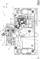
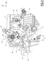
- the electrical protection device is described below with reference to the Figures 1 to 4 .
- FIG 1 shows a view from a first angle of an electrical protection device 1, also called device 1 according to the invention.
- this electrical protection device 1 is a circuit breaker, here a miniature circuit breaker called MCB, from the English “Miniature Circuit Breaker", but the invention can also be applied to other types of circuit breakers, or to other electrical devices intended for the protection of electrical installations and/or people.
- the device 1 protects the electrical installations against abnormal conditions, in particular short circuits ("short-circuit" in English) and current overloads ("overload” in English).
- the device 1 is more particularly intended to be used to protect electrical installations with low electrical voltage, for example electrical voltages less than or equal to 1000 V AC.
- the device 1 when the device 1 is in operation, it is connected to an electrical circuit, more precisely between an input conductor and an output conductor of the electrical circuit, not shown in the figures.
- the input conductor is for example a busbar and the output conductor is for example an electric cable.
- width direction X is horizontal and normal to the plane of the Figures 1 to 4 .
- the device 1 comprises a housing 2, essentially closed and containing the majority of the other elements of the device 1.
- the housing 2 is formed of an electrically insulating material.
- the directions X, Y and Z are fixed relative to the housing 2.
- the housing 2 comprises another half-shell 3 visible at the figure 2 and generally symmetrical to that which is represented, in relation to a plane P2 which delimits the half-shell 2 on its side.
- the device 1 comprises a movable contact 11 and a fixed contact 12.
- the movable contact 11 is generally called the phase movable contact 11, and the fixed contact 12 is generally called the phase fixed contact 12.
- the fixed contact 12 is fixed relative to the housing 2 and is connected to the input conductor of the electrical circuit.
- the movable contact 11 is connected to the output conductor of the electrical circuit, and is located opposite the fixed contact 12 in the height direction Z.
- the movable contact 11 preferably comprises a conductive end 13, providing the electrical contact function.
- the movable contact 11 preferably comprises a contact carrier 15, which carries the conductive end 13.
- the movable contact 11 is pivotable, relative to the housing 2, by means of the contact carrier 15, around a movable contact axis X11, parallel to the width direction X.
- This pivoting is carried out between a conduction position, shown in the figure 1 , and an isolation position, shown figure 4 .
- the conduction position of the movable contact 11 the conductive end 13 is in electrical contact with, and resting against, the fixed contact 12, allowing the passage of current between the input conductor and the output conductor of the electrical circuit.
- the movable phase contact 11 closes the electrical circuit.
- the isolation position the conductive end 13 of the movable contact 11 is spaced from the fixed contact 12, so as to be electrically isolated therefrom.
- the movable phase contact 11 opens the electrical circuit.
- the electrical protection device 1 advantageously comprises a second movable contact 21 and a second fixed contact 22, visible in the figure 2 .
- the second movable contact 21 is generally called the movable neutral contact 21 and the second fixed contact 22 is generally called the fixed neutral contact 22.
- the fixed neutral contact 22 is connected to the input conductor of the electrical circuit.
- the movable neutral contact 21 is connected to the output conductor of the electrical circuit.
- the movable neutral contact 21 preferably comprises a conductive end 23 and a contact holder 25, in a manner similar to that described for the movable phase contact 11.
- the movable neutral contact 21 is pivotable, relative to the housing 2, around the axis X11, that is to say around the same axis as that of the movable contact 11.
- the pivoting of the movable phase 11 and neutral 21 contacts is carried out around two distinct axes, preferably parallel to each other.
- the pivoting of the movable neutral contact 21 is carried out between a conduction position and an isolation position.
- the conductive end 23 is in electrical contact with, and resting against, the fixed neutral contact 22.
- the neutral movable contact 21 closes the electrical circuit.
- the isolation position the conductive end 23 of the neutral movable contact 21 is spaced from the fixed neutral contact 22, so as to be electrically isolated therefrom.
- the neutral movable contact 21 opens the electrical circuit.
- the moving phase 11 and neutral 21 contacts are advantageously pivotable relative to the housing 2 independently. When they move from their respective isolation positions to their respective conduction positions, the moving phase 11 and neutral 21 contacts advantageously rotate in the same direction. In particular, the conductive ends 13 and 23 are then moved essentially in a direction opposite to the direction Z. When the movable phase 11 and neutral 21 contacts are in the conduction position, the electrical circuit is closed, and electric current flows in the fixed phase contact 12 to the movable phase contact 11, and in the fixed neutral contact 22 to the movable neutral contact 21.
- the electrical protection device 1 further comprises at least one trigger.
- two triggers are shown, each configured to be excited by an electrical fault of a respective distinct predetermined type.
- Each trigger is designed to individually trigger a switching into the isolation position of the moving phase 11 and neutral 21 contacts, when one of the triggers is excited.
- one of the triggers is a thermal trigger 30 and is designed to be excited by a predetermined electrical fault, of the current overload type.
- the other trigger is a magnetic trigger 35 and is designed to be excited by a short circuit.
- Such triggers 30 and 35 are known per se and are not described in further detail.
- the device 1 comprises an additional trigger, configured to be excited by another electrical fault of a predetermined type, namely a differential type electrical fault.
- the device 1 is then a circuit breaker called RCBO, from the English “Residual Current Breaker with Overcurrent Protection”.
- the electrical protection device 1 also comprises a switching mechanism 40.
- the switching mechanism 40 is housed in the housing 2.
- the switching mechanism 40 is configured to switch between an armed configuration, shown in figure 1 , in which the switching mechanism 40 places the movable phase 11 and neutral 21 contacts in the conduction position, and a triggered configuration, partially shown in the figure 4 , in which the switching mechanism 40 places the movable phase 11 and neutral 21 contacts in the isolated position.
- a first contact spring 45 bears against the first movable contact 11, in particular against the contact carrier 15, and against the switching mechanism 40.
- a second contact spring 46 bears against the second movable contact 21, in particular against the contact carrier 25 and against the switching mechanism 40.
- the contact springs 45 and 46 are helical torsion springs. It is expected that the first and second contact springs 45 and 46 apply, respectively to the movable phase 11 and neutral 21 contacts, a torque about the axis X11 which tends to place the moving phase 11 and neutral 21 contacts against the fixed phase and neutral 12 and 22 contacts.
- the electrical protection device 1 also comprises a switching handle 50.
- the switching handle 50 is designed to be actuated by a user, between an open position and a closed position and vice versa.
- the switching handle 50 is pivotable relative to the housing 2, about a handle axis X50, parallel to the direction X, between a closed position, shown in the Figures 1 to 3 , and an opening position, shown on the figure 4 .
- the switching lever 50 here comprises a base 51, via which the switching lever 50 is pivotally mounted on the housing 2.
- the switching lever 50 comprises a crank pin 52, carried by the base 51, and via which the user can actuate the switching lever 50 in rotation, by exerting a torque about the lever axis X50.
- the crank pin 52 is arranged at least partly outside the housing 2.
- the switching mechanism 40 advantageously comprises a spring, called a "control spring”, not shown.
- the control spring applies, on the switching lever 50 and by bearing on the housing 2, a torque around the lever axis X50 which tends to return the switching lever 50 from its closed position to its open position.
- the control spring is a helical torsion spring, housed inside the base 51 around the lever axis X50, and one branch of which bears on the switching lever 50 and another branch bears on the inside of the housing 2.
- the position of the switching handle 50 visually indicates to the user the current configuration controlled for the electrical protection device 1, namely a positioning of the phase 11 and neutral 21 moving contacts in the isolation position when the switching handle 50 is in the open position, and a positioning of the phase 11 and neutral 21 moving contacts in the conduction position, when the switching handle 50 is in the closed position.
- the switching mechanism 40 advantageously comprises a connecting rod 42, visible in the figure 2 .
- the connecting rod 42 connects the switching handle 50 to the rest of the switching mechanism 40.
- This duration threshold T s is advantageously of the order of a few milliseconds, for example between 4 and 8 ms, for example equal to 6 ms.
- This delay T is due in particular to the time required to move the moving contacts 11 and 21, the switching mechanism 40 and the switching handle 50 following detection of the fault by the trigger 30 or 35, and to the torque of the springs, in particular of the control spring.
- a user by actuating the handle 52, can then switch the switching lever 50 from the open position to the closed position, thereby causing the moving phase 11 and neutral 21 contacts to be placed in the conduction position from the isolation position, in order to reset the device 1 and close the electrical circuit.
- a user by actuating the toggle 52, can switch the switching handle 50 from the closed position to the open position, thereby causing the moving phase 11 and neutral 21 contacts to be placed in the isolation position from the conduction position, for example to perform operations on the electrical circuit, or to check the proper operation of the device 1.
- the switching handle 50 moves from the closed position to the open position almost simultaneously with the moving phase 11 and neutral 21 contacts to the isolation position.
- almost simultaneous it is meant that the duration T between the switching handle 50 moving from the closed position to the open position and the moving phase 11 and neutral 21 contacts to the isolation position is less than the duration threshold T s .
- the device 1 further comprises an electrical connection element 60, a switch 70, a mechanical connection element 80, a current sensor 85 and an electronic control unit 90, which cooperate advantageously, as described in more detail below, to determine the position of the movable contacts 11 and 21 and of the switching handle 50, and to determine the cause of an opening of the electrical circuit by the device 1.
- the electrical connection element 60 is for example a spring and comprises an end 61 and an end 63 opposite the end 61.
- the end 61 of the electrical connection element 60 is connected to the electronic control unit 90.
- a first voltage V 1 can be measured at the electrical connection element 60. If this first voltage V 1 is non-zero, this indicates that the phase movable contact 11 is in a closed state. On the contrary, the first voltage V 1 is zero when the phase movable contact 11 is in an open state. In other words, when the phase movable contact 11 is in the conduction position, the first voltage V 1 is non-zero and a current flows from the phase movable contact 11 into the electrical connection element 60. When the phase movable contact 11 is in the isolation position, the first voltage V 1 is zero, no current flows into the electrical connection element 60. Thus, the first voltage V 1 is representative of the position of the phase movable contact 11 in the conduction or isolation position.
- the end of the electrical connection element 60 is in contact with the moving neutral contact 21 when the moving neutral contact 21 is in the conduction position and not the moving phase contact.
- the switch 70 is connected to the electronic control unit 90, for example by a wired connection.
- a second voltage V 2 can be measured at the switch 70.
- the switch 70 is movable between a depressed position, visible at the figure 3 , and a free position, visible at the figure 4 .
- the second voltage V 2 varies depending on the free or pressed position of the switch 70.
- the second voltage V 2 is non-zero, i.e. of a value greater than a single predetermined value, the threshold being equal for example to a few millivolts, and in the free position, the second voltage V 2 is zero, i.e. of a value lower than said predetermined threshold.
- the second voltage V 2 is zero when the switch 70 is in the depressed position, and non-zero when it is in the free position.
- this alternative embodiment makes it possible to reduce energy consumption.
- the second voltage V 2 is representative of the position of the switch 70, between the depressed position and the free position.
- the switch 70 is by default in the free position, so that when no stress is exerted on the switch 70, it remains in the free position.
- the mechanical connecting element 80 is visible on the figures 1 , 3 And 4 .
- the mechanical connecting element 80 is connected to the switching lever 50, more precisely to the base 51, so as to be movable at the same time as the switching lever 50.
- the mechanical connecting element 80 is a connecting rod.
- the mechanical connecting element 80 could be made in another form, for example a rotating plate, a translating drawer, or even a belt.
- One end 81 of the mechanical connecting element 80 is opposite the switch 70 along the Y axis, and is movable between a support position and a release position. In the support position, visible on the figure 3 , the end 81 presses the switch 70 in a direction opposite to the direction Y and keeps it in the pressed position. In the released position, visible on the figure 4 , the end 81 no longer presses the switch 70, which is then in the free position.
- the mechanical connecting element 80 is therefore in the support position when the switching handle 50 is closed and in the release position when the switching handle 50 is open.
- the mechanical connecting element is in the support position when the switching handle is open and in the release position when the switching handle is closed.
- the second voltage V 2 is representative of the position of the switching handle 50, between the closed position and the open position.
- the current sensor 85 is housed inside the housing 2.
- the current sensor 85 is configured to measure an intensity I of the current flowing through the device 1.
- the electronic control unit 90 is housed inside the housing 2, a portion of the electronic control unit being visible on the figure 1 and the other part being visible on the figure 2 .
- the electronic control unit 90 is an electronic card.
- the electronic control unit 90 may be produced in a form other than an electronic card, for example in the form of a dry contact connected to a wired data concentrator.
- the electronic control unit 90 is configured to determine a cause of opening of the electrical circuit, between a manual opening, i.e. caused by a user who switches the switching lever 50 from the closed position to the open position, and an opening on fault, caused by one of the triggers 30 or 35.
- the electronic control unit 90 comprises a memory, configured to continuously record a value of the intensity I of the current, and in particular to record the value of the intensity I of the current before a possible opening of the electrical circuit.
- the electronic control unit 90 makes it possible to store a value of the current I just before a possible opening of the device.
- the electronic control unit 90 measures the first voltage V 1 and the second voltage V 2 , and compares the first voltage V 1 to a first voltage threshold V s1 and the second voltage V 2 to a second voltage threshold V s2 , in order to determine, when the electrical circuit opens, whether this opening is caused by a manual opening or an opening on a fault.
- the control unit electronics 90 is also configured to send a first signal, if the cause of opening is a manual opening, and a second and/or a third signal if the cause of opening is an opening on fault.
- the electronic control unit 90 is configured to send the second signal when the trigger 30 causes the electrical circuit to open, and to send the third signal when the trigger 35 causes the electrical circuit to open.
- the signals are for example signals sent wirelessly to a human-machine interface, not shown, which displays to the user the cause of the opening of the electrical circuit by the device 1.
- additional information on the cause of the opening is also displayed. For example, if the first signal is sent, the human-machine interface simply displays a manual opening, but if the second or third signal is sent, the human-machine interface displays for example the type of electrical fault and/or steps to follow to verify that the electrical fault does not persist in the electrical circuit.
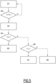
- the method comprises a step 201 of measuring the first and second voltages V 1 and V 2 .
- the measurement is carried out by the electronic card 90.
- the measurement step 201 is for example carried out with a frequency equal to or greater than the frequency of the input current of the device 1 (for example 50Hz in France).
- the method also comprises a comparison 202 of the first voltage V 1 to the first voltage threshold V s1 . If the first voltage V 1 is of a value greater than or equal to the first voltage threshold V s1 , the method returns to step 201. This corresponds to a situation where the electrical circuit is closed.
- a step 203 is then carried out, and consists of a measurement of the duration T between a moment when the first voltage V 1 becomes lower than the first voltage threshold V s1 , corresponding to the moment when the phase movable contact 11 switches to the isolation position, and a moment when the second voltage V 2 becomes lower than the second voltage threshold V s2 , corresponding to the moment when the switching handle 50 switches to the opening position.
- the method further comprises a comparison 204 of the duration T measured in step 203 with the duration threshold T s . If the duration T is less than the duration threshold T s , then the Switch lever 50 and phase contact 11 were moved almost simultaneously, which corresponds to manual opening.
- a step 205 is performed, in which the electronic control unit 90 sends the first signal.
- This first signal is advantageously received by the human-machine interface in order to generate a display indicating to the user that the cause of opening is a manual opening.
- the switching lever 50 has been moved after the phase moving contact 11 has moved to the isolation position, which corresponds to an opening on fault.
- a step 206 is performed, in which the intensity I of the current measured by the current sensor 85 before the opening of the device 1 and recorded by the memory of the electronic card 90, is compared with a current threshold I s .
- the current threshold I s is advantageously calculated according to a nominal intensity of the electrical circuit, and is equal to the nominal intensity flowing in the electrical circuit multiplied by a predetermined value, this value being for example equal to three. If the nominal intensity of the electrical circuit is 32A, then the current threshold I s is for example 96A.
- step 207 is carried out, step 207 consisting of the sending of the second signal by the electronic control unit 90.
- This second signal is advantageously received by the human-machine interface in order to generate a display indicating to the user that the cause of opening is an opening on fault following a current overload in the electrical circuit.
- a step 208 is carried out, consisting of the sending of the third signal by the electronic control unit 90.
- This third signal is advantageously received by the human-machine interface in order to generate a display indicating to the user that the cause of opening is an opening on fault following a short circuit in the electrical circuit.
- Recording the current intensity I by the memory of the electronic card 90 thus makes it possible, in the event of device 1 opening due to a fault, to determine the cause of the fault between a current overload or a short circuit.
- steps 206 and 207 are not performed, and a step corresponding to the sending of the second signal is performed instead.
- the second signal corresponds in this case to an opening on fault, without specifying the nature of the fault.
- FIG. 6 represents a variation of the first and second voltages V 1 and V 2 in the case of manual opening and in the case of opening on fault.
- the voltages V 1 and V 2 decrease at the same time.
- the duration T between the moment when the first voltage V 1 became lower than the first voltage threshold V s1 and the moment when the second voltage V 2 becomes lower than the second voltage threshold V s2 is lower than the duration threshold T s .
- the duration T between the moment when the first voltage V 1 became lower than the first voltage threshold V s1 and the moment when the second voltage V 2 became lower than the second voltage threshold V s2 is greater than the duration threshold T s .
- the first voltage V 1 is represented as being greater than the second voltage V 2 . According to other variants not shown, the first voltage V 1 is less than the second voltage V 2 , or equal to the second voltage V 2 .
- the electronic control unit 90 measures a first and a second current and compares them to a first current threshold and a second current threshold.
- a fourth signal, corresponding to an absence of current upstream of the device 1 is emitted when the first voltage is lower than the first voltage threshold and the second voltage remains higher than the second voltage threshold, for a duration greater than a network fault duration threshold, greater than the duration threshold T s .
- the first voltage becomes zero, but this is not caused by the moving phase contact being placed in the isolation position.
- the lever does not switch to the open position. This makes it possible to distinguish an absence of current due to a cut-off upstream of the device from an electrical fault in the electrical circuit.
- the second and/or third signals are sent only once the network fault duration threshold has been reached, to avoid sending the second and/or third signal once the duration threshold has been reached, and sending the fourth signal once the network fault duration threshold has been reached, which could lead to confusion about the nature of the fault detected by the device.
- the electrical connection element 60, the switch 70, the mechanical connection element 80, the current sensor 85 and the electronic control unit 90 together perform a functionality called OFSD, or “Open Closed Signal Fault”, allowing the user to identify the cause of the opening of the electrical circuit between a manual cause and a cause on fault, and advantageously, in the event of an electrical fault, to also know what type of electrical fault generated the opening of the circuit. This facilitates the remote control of the device 1, in particular to determine whether it is necessary to intervene following an electrical fault, or not.
- OFSD Open Closed Signal Fault
- the elements used to automatically determine the cause of opening and their arrangement make it possible to maintain the compactness of the protection device 1, in particular in the width direction X.
- the housing 2 may have a width measured in the width direction X of less than 20 mm, preferably equal to 18 mm.
Landscapes
- Physics & Mathematics (AREA)
- Electromagnetism (AREA)
- Engineering & Computer Science (AREA)
- Power Engineering (AREA)
- Breakers (AREA)
- Emergency Protection Circuit Devices (AREA)
- Protection Of Static Devices (AREA)
- Keying Circuit Devices (AREA)
Applications Claiming Priority (1)
| Application Number | Priority Date | Filing Date | Title |
|---|---|---|---|
| FR2308369A FR3151912A1 (fr) | 2023-08-02 | 2023-08-02 | Dispositif de protection électrique configuré pour déterminer automatiquement une cause d’une ouverture d’un circuit électrique et procédé associé |
Publications (1)
| Publication Number | Publication Date |
|---|---|
| EP4503083A1 true EP4503083A1 (de) | 2025-02-05 |
Family
ID=88584994
Family Applications (1)
| Application Number | Title | Priority Date | Filing Date |
|---|---|---|---|
| EP24192429.9A Pending EP4503083A1 (de) | 2023-08-02 | 2024-08-01 | Elektrische schutzvorrichtung, die zur automatischen bestimmung einer ursache einer öffnung einer elektrischen schaltung konfiguriert ist, und verfahren dafür |
Country Status (5)
| Country | Link |
|---|---|
| US (1) | US20250046557A1 (de) |
| EP (1) | EP4503083A1 (de) |
| CN (1) | CN119446860A (de) |
| AU (1) | AU2024205169A1 (de) |
| FR (1) | FR3151912A1 (de) |
Citations (1)
| Publication number | Priority date | Publication date | Assignee | Title |
|---|---|---|---|---|
| EP3790034A1 (de) * | 2019-09-05 | 2021-03-10 | Schneider Electric Industries SAS | Elektronisches hilfsschutzmodul und entsprechende schutzschaltervorrichtung |
-
2023
- 2023-08-02 FR FR2308369A patent/FR3151912A1/fr not_active Ceased
-
2024
- 2024-07-26 US US18/785,128 patent/US20250046557A1/en active Pending
- 2024-07-29 AU AU2024205169A patent/AU2024205169A1/en active Pending
- 2024-08-01 CN CN202411047255.3A patent/CN119446860A/zh active Pending
- 2024-08-01 EP EP24192429.9A patent/EP4503083A1/de active Pending
Patent Citations (1)
| Publication number | Priority date | Publication date | Assignee | Title |
|---|---|---|---|---|
| EP3790034A1 (de) * | 2019-09-05 | 2021-03-10 | Schneider Electric Industries SAS | Elektronisches hilfsschutzmodul und entsprechende schutzschaltervorrichtung |
Also Published As
| Publication number | Publication date |
|---|---|
| CN119446860A (zh) | 2025-02-14 |
| FR3151912A1 (fr) | 2025-02-07 |
| AU2024205169A1 (en) | 2025-02-20 |
| US20250046557A1 (en) | 2025-02-06 |
Similar Documents
| Publication | Publication Date | Title |
|---|---|---|
| EP0537084B1 (de) | Schutzschalter mit selektiver Verriegelung | |
| EP2254136B1 (de) | Apparat zur Bestimmung der Integrität von Kontakten, die durch die Variation der Wellendrehung der Pole gedrückt sind und sein Herstellungsverfahren | |
| WO2003054895A1 (fr) | Procede pour determiner l'usure des contacts d'un appareil interrupteur | |
| FR2604294A1 (fr) | Disjoncteur differentiel multipolaire a assemblage modulaire | |
| FR2912547A1 (fr) | Disjoncteur de defaut d'arc serie | |
| EP0007867A1 (de) | Verbesserungen an Vorrichtungen zum Feststellen des Bruchs eines Elements einer elektrischen Schaltung | |
| EP4167261A1 (de) | Elektrische schaltvorrichtung, entsprechendes schaltsystem und verfahren | |
| FR2863403A1 (fr) | Dispositif de signalisation du declenchement d'un appareil de protection electrique et appareil de protection electrique le comportant | |
| EP2849195A1 (de) | Zusatzvorrichung für elektrischen Schutzschalter, elektrisches System mit einem Schutzschalter und dieser Zusatzvorrichtung und Verfahren zur Bestimmung des Grunds der Öffnung des Schutzshalters dank dieser Zusatzvorrichtung | |
| EP2824677A1 (de) | Vorrichtung zur Erkennung der Entsperrung eines Trennschalters, Stellglied eines Kontakttrennungsmechanismus des Trennschalters, elektrischer Trennschalter und Verwendung eines induzierten Stroms zur Erzeugung eines Anzeigesignals der Entsperrung | |
| EP1557922B1 (de) | Differentialschutzvorrichtung mit vereinfachten Einstellmitteln für die Schutzparameter | |
| FR2672744A1 (fr) | Dispositif selectif et automatique de securite electrique. | |
| FR3151912A1 (fr) | Dispositif de protection électrique configuré pour déterminer automatiquement une cause d’une ouverture d’un circuit électrique et procédé associé | |
| EP3790034A1 (de) | Elektronisches hilfsschutzmodul und entsprechende schutzschaltervorrichtung | |
| EP2743958B1 (de) | Elektrisches Stromschaltgerät, insbesondere Abzweigschalter | |
| EP0665623A1 (de) | Prüfeinrichtung für Differentialschutzschalter und diese Vorrichtung enthaltende Differentialschutzschalter | |
| EP2693585B1 (de) | Schutzsystem für eine Vielzahl von elektrischen Ableitungen gegen Kurzschlüsse, und Elektroanlage, die ein solches Schutzsystem umfasst | |
| EP3977577B1 (de) | Schutzvorrichtung für stromleitung (l) zum erkennen eines leckfehlers, kurzschlusses, fehlers, überstromfehlers und lichtbogenfehlers | |
| FR2817972A1 (fr) | Systeme de detection de defaillance d'un cable dans un reseau arborescent | |
| EP3718126B1 (de) | Modulares elektrisches schaltgerät | |
| FR2526519A1 (fr) | Dispositif de securite de mise en route d'un appareil electrique | |
| EP1544884A1 (de) | Beweglicher Schutzschalter mit Rückstellberechtigungsmechanismus. | |
| EP2463885A2 (de) | Elektrischer Schutzschalter mit Strombegrenzer | |
| FR2999794A1 (fr) | Dispositif de declenchement thermique et appareil de coupure du courant comportant un tel dispositif, en particulier un disjoncteur de branchement. | |
| EP1647041B1 (de) | Mit einer testschaltung ausgestatteter differenz-schalter |
Legal Events
| Date | Code | Title | Description |
|---|---|---|---|
| PUAI | Public reference made under article 153(3) epc to a published international application that has entered the european phase |
Free format text: ORIGINAL CODE: 0009012 |
|
| STAA | Information on the status of an ep patent application or granted ep patent |
Free format text: STATUS: THE APPLICATION HAS BEEN PUBLISHED |
|
| AK | Designated contracting states |
Kind code of ref document: A1 Designated state(s): AL AT BE BG CH CY CZ DE DK EE ES FI FR GB GR HR HU IE IS IT LI LT LU LV MC ME MK MT NL NO PL PT RO RS SE SI SK SM TR |
|
| STAA | Information on the status of an ep patent application or granted ep patent |
Free format text: STATUS: REQUEST FOR EXAMINATION WAS MADE |
|
| 17P | Request for examination filed |
Effective date: 20250708 |