EP4503177A1 - Folie für elektrode, elektrode damit, sekundärbatterie und verfahren zur herstellung davon - Google Patents
Folie für elektrode, elektrode damit, sekundärbatterie und verfahren zur herstellung davon Download PDFInfo
- Publication number
- EP4503177A1 EP4503177A1 EP23792222.4A EP23792222A EP4503177A1 EP 4503177 A1 EP4503177 A1 EP 4503177A1 EP 23792222 A EP23792222 A EP 23792222A EP 4503177 A1 EP4503177 A1 EP 4503177A1
- Authority
- EP
- European Patent Office
- Prior art keywords
- electrode
- electrode film
- fluorine
- containing binder
- active material
- Prior art date
- Legal status (The legal status is an assumption and is not a legal conclusion. Google has not performed a legal analysis and makes no representation as to the accuracy of the status listed.)
- Pending
Links
Images
Classifications
-
- H—ELECTRICITY
- H01—ELECTRIC ELEMENTS
- H01M—PROCESSES OR MEANS, e.g. BATTERIES, FOR THE DIRECT CONVERSION OF CHEMICAL ENERGY INTO ELECTRICAL ENERGY
- H01M4/00—Electrodes
- H01M4/02—Electrodes composed of, or comprising, active material
- H01M4/04—Processes of manufacture in general
- H01M4/043—Processes of manufacture in general involving compressing or compaction
- H01M4/0435—Rolling or calendering
-
- H—ELECTRICITY
- H01—ELECTRIC ELEMENTS
- H01M—PROCESSES OR MEANS, e.g. BATTERIES, FOR THE DIRECT CONVERSION OF CHEMICAL ENERGY INTO ELECTRICAL ENERGY
- H01M4/00—Electrodes
- H01M4/02—Electrodes composed of, or comprising, active material
- H01M4/36—Selection of substances as active materials, active masses, active liquids
- H01M4/48—Selection of substances as active materials, active masses, active liquids of inorganic oxides or hydroxides
- H01M4/52—Selection of substances as active materials, active masses, active liquids of inorganic oxides or hydroxides of nickel, cobalt or iron
- H01M4/525—Selection of substances as active materials, active masses, active liquids of inorganic oxides or hydroxides of nickel, cobalt or iron of mixed oxides or hydroxides containing iron, cobalt or nickel for inserting or intercalating light metals, e.g. LiNiO2, LiCoO2 or LiCoOxFy
-
- H—ELECTRICITY
- H01—ELECTRIC ELEMENTS
- H01M—PROCESSES OR MEANS, e.g. BATTERIES, FOR THE DIRECT CONVERSION OF CHEMICAL ENERGY INTO ELECTRICAL ENERGY
- H01M4/00—Electrodes
- H01M4/02—Electrodes composed of, or comprising, active material
- H01M4/62—Selection of inactive substances as ingredients for active masses, e.g. binders, fillers
- H01M4/621—Binders
- H01M4/622—Binders being polymers
- H01M4/623—Binders being polymers fluorinated polymers
-
- H—ELECTRICITY
- H01—ELECTRIC ELEMENTS
- H01M—PROCESSES OR MEANS, e.g. BATTERIES, FOR THE DIRECT CONVERSION OF CHEMICAL ENERGY INTO ELECTRICAL ENERGY
- H01M10/00—Secondary cells; Manufacture thereof
- H01M10/05—Accumulators with non-aqueous electrolyte
- H01M10/052—Li-accumulators
- H01M10/0525—Rocking-chair batteries, i.e. batteries with lithium insertion or intercalation in both electrodes; Lithium-ion batteries
-
- H—ELECTRICITY
- H01—ELECTRIC ELEMENTS
- H01M—PROCESSES OR MEANS, e.g. BATTERIES, FOR THE DIRECT CONVERSION OF CHEMICAL ENERGY INTO ELECTRICAL ENERGY
- H01M4/00—Electrodes
- H01M4/02—Electrodes composed of, or comprising, active material
- H01M4/04—Processes of manufacture in general
- H01M4/0402—Methods of deposition of the material
- H01M4/0404—Methods of deposition of the material by coating on electrode collectors
-
- H—ELECTRICITY
- H01—ELECTRIC ELEMENTS
- H01M—PROCESSES OR MEANS, e.g. BATTERIES, FOR THE DIRECT CONVERSION OF CHEMICAL ENERGY INTO ELECTRICAL ENERGY
- H01M4/00—Electrodes
- H01M4/02—Electrodes composed of, or comprising, active material
- H01M4/04—Processes of manufacture in general
- H01M4/0471—Processes of manufacture in general involving thermal treatment, e.g. firing, sintering, backing particulate active material, thermal decomposition, pyrolysis
-
- H—ELECTRICITY
- H01—ELECTRIC ELEMENTS
- H01M—PROCESSES OR MEANS, e.g. BATTERIES, FOR THE DIRECT CONVERSION OF CHEMICAL ENERGY INTO ELECTRICAL ENERGY
- H01M4/00—Electrodes
- H01M4/02—Electrodes composed of, or comprising, active material
- H01M4/13—Electrodes for accumulators with non-aqueous electrolyte, e.g. for lithium-accumulators; Processes of manufacture thereof
- H01M4/136—Electrodes based on inorganic compounds other than oxides or hydroxides, e.g. sulfides, selenides, tellurides, halogenides or LiCoFy
-
- H—ELECTRICITY
- H01—ELECTRIC ELEMENTS
- H01M—PROCESSES OR MEANS, e.g. BATTERIES, FOR THE DIRECT CONVERSION OF CHEMICAL ENERGY INTO ELECTRICAL ENERGY
- H01M4/00—Electrodes
- H01M4/02—Electrodes composed of, or comprising, active material
- H01M4/13—Electrodes for accumulators with non-aqueous electrolyte, e.g. for lithium-accumulators; Processes of manufacture thereof
- H01M4/139—Processes of manufacture
- H01M4/1391—Processes of manufacture of electrodes based on mixed oxides or hydroxides, or on mixtures of oxides or hydroxides, e.g. LiCoOx
-
- H—ELECTRICITY
- H01—ELECTRIC ELEMENTS
- H01M—PROCESSES OR MEANS, e.g. BATTERIES, FOR THE DIRECT CONVERSION OF CHEMICAL ENERGY INTO ELECTRICAL ENERGY
- H01M4/00—Electrodes
- H01M4/02—Electrodes composed of, or comprising, active material
- H01M4/13—Electrodes for accumulators with non-aqueous electrolyte, e.g. for lithium-accumulators; Processes of manufacture thereof
- H01M4/139—Processes of manufacture
- H01M4/1397—Processes of manufacture of electrodes based on inorganic compounds other than oxides or hydroxides, e.g. sulfides, selenides, tellurides, halogenides or LiCoFy
-
- H—ELECTRICITY
- H01—ELECTRIC ELEMENTS
- H01M—PROCESSES OR MEANS, e.g. BATTERIES, FOR THE DIRECT CONVERSION OF CHEMICAL ENERGY INTO ELECTRICAL ENERGY
- H01M4/00—Electrodes
- H01M4/02—Electrodes composed of, or comprising, active material
- H01M4/36—Selection of substances as active materials, active masses, active liquids
- H01M4/58—Selection of substances as active materials, active masses, active liquids of inorganic compounds other than oxides or hydroxides, e.g. sulfides, selenides, tellurides, halogenides or LiCoFy; of polyanionic structures, e.g. phosphates, silicates or borates
- H01M4/5825—Oxygenated metallic salts or polyanionic structures, e.g. borates, phosphates, silicates, olivines
-
- H—ELECTRICITY
- H01—ELECTRIC ELEMENTS
- H01M—PROCESSES OR MEANS, e.g. BATTERIES, FOR THE DIRECT CONVERSION OF CHEMICAL ENERGY INTO ELECTRICAL ENERGY
- H01M4/00—Electrodes
- H01M4/02—Electrodes composed of, or comprising, active material
- H01M4/64—Carriers or collectors
- H01M4/66—Selection of materials
- H01M4/665—Composites
- H01M4/667—Composites in the form of layers, e.g. coatings
-
- H—ELECTRICITY
- H01—ELECTRIC ELEMENTS
- H01M—PROCESSES OR MEANS, e.g. BATTERIES, FOR THE DIRECT CONVERSION OF CHEMICAL ENERGY INTO ELECTRICAL ENERGY
- H01M4/00—Electrodes
- H01M4/02—Electrodes composed of, or comprising, active material
- H01M2004/021—Physical characteristics, e.g. porosity, surface area
-
- H—ELECTRICITY
- H01—ELECTRIC ELEMENTS
- H01M—PROCESSES OR MEANS, e.g. BATTERIES, FOR THE DIRECT CONVERSION OF CHEMICAL ENERGY INTO ELECTRICAL ENERGY
- H01M4/00—Electrodes
- H01M4/02—Electrodes composed of, or comprising, active material
- H01M2004/026—Electrodes composed of, or comprising, active material characterised by the polarity
- H01M2004/028—Positive electrodes
-
- H—ELECTRICITY
- H01—ELECTRIC ELEMENTS
- H01M—PROCESSES OR MEANS, e.g. BATTERIES, FOR THE DIRECT CONVERSION OF CHEMICAL ENERGY INTO ELECTRICAL ENERGY
- H01M4/00—Electrodes
- H01M4/02—Electrodes composed of, or comprising, active material
-
- H—ELECTRICITY
- H01—ELECTRIC ELEMENTS
- H01M—PROCESSES OR MEANS, e.g. BATTERIES, FOR THE DIRECT CONVERSION OF CHEMICAL ENERGY INTO ELECTRICAL ENERGY
- H01M4/00—Electrodes
- H01M4/02—Electrodes composed of, or comprising, active material
- H01M4/62—Selection of inactive substances as ingredients for active masses, e.g. binders, fillers
- H01M4/624—Electric conductive fillers
- H01M4/625—Carbon or graphite
-
- Y—GENERAL TAGGING OF NEW TECHNOLOGICAL DEVELOPMENTS; GENERAL TAGGING OF CROSS-SECTIONAL TECHNOLOGIES SPANNING OVER SEVERAL SECTIONS OF THE IPC; TECHNICAL SUBJECTS COVERED BY FORMER USPC CROSS-REFERENCE ART COLLECTIONS [XRACs] AND DIGESTS
- Y02—TECHNOLOGIES OR APPLICATIONS FOR MITIGATION OR ADAPTATION AGAINST CLIMATE CHANGE
- Y02E—REDUCTION OF GREENHOUSE GAS [GHG] EMISSIONS, RELATED TO ENERGY GENERATION, TRANSMISSION OR DISTRIBUTION
- Y02E60/00—Enabling technologies; Technologies with a potential or indirect contribution to GHG emissions mitigation
- Y02E60/10—Energy storage using batteries
Definitions
- the present disclosure relates to an electrode film, an electrode including the same, a secondary battery, and a method for manufacturing the same. Particularly, the present disclosure relates to an electrode film having improved mechanical properties, an electrode including the same, a secondary battery, and a method for manufacturing the same.
- a lithium secondary battery as a representative of such secondary batteries has been used not only as an energy source of mobile instruments but also as a power source of electric vehicles and hybrid electric vehicles capable of substituting for vehicles, such as gasoline vehicles and diesel vehicles, using fossil fuel and regarded as one of the main causes of air pollution, recently.
- application of such a lithium secondary battery has been extended even to a supplementary power source of electric power through the formation into a grid.
- a process of manufacturing such a lithium secondary battery is broadly divided into the three steps of an electrode-forming step, an electrode assembly-forming step and an aging step.
- the electrode-forming step is further divided into an electrode mixture-mixing step, an electrode coating step, a drying step, a pressing step, a slitting step, a winding step, or the like.
- the electrode mixture-mixing step is a step of mixing the ingredients for forming an electrode active layer configured to carry out electrochemical reactions actually in the electrode.
- an electrode active material as an essential element of the electrode is mixed with other additives, including a conductive material and a filler, a binder used for the binding of powder particles among themselves and the adhesion to a current collector, a solvent for imparting viscosity and dispersing powder, or the like, to prepare a slurry having flowability.
- an electrode-coating step of applying the slurry onto a current collector having electrical conductivity and a drying step of removing the solvent contained in the electrode mixture are carried out, and then the resultant electrode is pressed to a predetermined thickness.
- the electrode active layer is not dried uniformly at the internal part and external part thereof, and thus a powder floating phenomenon may occur due to a difference in solvent evaporation rate. In other words, a powder present in a portion dried earlier may float, while forming a gap from a portion dried relatively later, resulting in degradation of electrode quality.
- drying apparatus which allows uniform drying of the internal and external parts of an electrode active layer and can control the evaporation rate of a solvent.
- drying apparatuses are expensive and require a lot of costs and times for their operation, and thus are disadvantageous in terms of manufacture processability.
- a method for manufacturing a dry electrode includes a step of subjecting a mixture of a binder (such as polytetrafluoroethylene (PTFE)) capable of fibrilization, an active material and a conductive material to a roll calendering process to obtain a free-standing electrode film.
- a binder such as polytetrafluoroethylene (PTFE)
- PTFE polytetrafluoroethylene
- the present disclosure is designed to solve the problems of the related art, and therefore the present disclosure is directed to providing an electrode film having improved mechanical properties, an electrode and secondary battery including the same, and a method for manufacturing the same.
- an electrode according to any one of the following embodiments.
- an electrode film including an active material and a fluorine-containing binder, wherein the fluorine-containing binder includes a polytetrafluoroethylene (PTFE) binder, the active material includes a lithium metal phosphate and the content of the fluorine-containing binder is 0.5-10 parts by weight based on 100 parts by weight of the total weight of the electrode film, and which shows an elongation at break of 3.5% or more.
- PTFE polytetrafluoroethylene
- the electrode film as defined in the first embodiment wherein the lithium metal phosphate is represented by the following Chemical Formula 1, and may include LiMPO 4 (wherein M is Fe, Co, Ni or Mn): [Chemical Formula 1] LiFe 1-a M a P x M' 1-x O 4 wherein M represents Cu, Mn, Cr, Zn, Pb, Ca, Co, Ni, Sr, Nb, Ti, or two or more of them, 0 ⁇ a ⁇ 0.01, M' represents Si, B, N, or two or more of them, and 0 ⁇ x ⁇ 0.9.
- LiMPO 4 wherein M is Fe, Co, Ni or Mn
- the electrode film as defined in the first or the second embodiment wherein the lithium metal phosphate includes LiFePO 4 .
- the electrode film as defined in any one of the first to the third embodiments, which shows an elongation at break of 3.5-6.5%, when the active material is a lithium metal phosphate.
- the electrode film as defined in any one of the first to the fourth embodiments, which includes an active material, a fluorine-containing binder and a conductive material.
- the electrode film as defined in the fifth embodiment wherein the conductive material includes activated carbon, graphite, carbon black, ketjen black, carbon nanotubes, or two or more of them.
- the electrode film as defined in the fifth or the sixth embodiment, wherein the content of the active material is 85-98 parts by weight, the content of the conductive material is 0.5-5 parts by weight, and the content of the fluorine-containing binder is 0.5-10 parts by weight.
- the electrode film as defined in any one of the first to the seventh embodiments which is obtained through a dry process.
- the ninth embodiment of the present disclosure there is provided a method for manufacturing the electrode film as defined in any one of the first to the eighth embodiments, including the steps of:
- the method for manufacturing the electrode film as defined in the ninth embodiment wherein the step of kneading the mixture to prepare mixture lumps is carried out in a kneader under a pressure equal to or higher than ambient pressure.
- a method for manufacturing an electrode including a step of laminating the electrode film as defined in any one of the first to the eighth embodiments on a current collector.
- the method for manufacturing an electrode as defined in the eleventh embodiment wherein the electrode film has a compression ratio of 30-50% in the step of laminating.
- an electrode including: a current collector; and the electrode film as defined in any one of the first to the eighth embodiments, disposed on at least one surface of the current collector.
- the electrode as defined in the thirteenth embodiment, wherein the current collector further includes a conductive primer layer on at least one surface thereof.
- a secondary battery including a positive electrode, a negative electrode and a separator interposed between the positive electrode and the negative electrode, wherein at least one of the positive electrode and the negative electrode is the electrode as defined in the thirteenth or the fourteenth embodiment.
- an energy storage system including the secondary battery as defined in the fifteenth embodiment as a unit cell.
- an electrode film is obtained by heat treating a fluorine-containing binder at 290-3 10°C and mixing the heat treated binder with an active material, or the like.
- the fluorine-containing binder is preliminarily heat treated, the binding of the primary particles among themselves in the secondary particles of the fluorine-containing binder (such as PTFE) is improved by virtue of melt inter-diffusion on the surface between the binder particles, thereby facilitating the fibrilization of the fluorine-containing binder in the subsequent process for manufacturing an electrode film.
- the electrode film includes a fluorine-containing binder the fibrilization of which is accomplished to a higher degree as compared to the conventional electrode film, and thus shows significantly improved mechanical properties and increased film productivity.
- an electrode film including an active material and a fluorine-containing binder, wherein the fluorine-containing binder includes a polytetrafluoroethylene (PTFE) binder, the active material includes a lithium metal phosphate and the content of the fluorine-containing binder is 0.5-10 parts by weight based on 100 parts by weight of the total weight of the electrode film, and which shows an elongation at break of 3.5% or more.
- PTFE polytetrafluoroethylene
- the lithium metal phosphate may be represented by the following Chemical Formula 1: [Chemical Formula 1] LiFe 1-a M a P x M' 1-x O 4 wherein M represents Cu, Mn, Cr, Zn, Pb, Ca, Co, Ni, Sr, Nb, Ti, or two or more of them, 0 ⁇ a ⁇ 0.01, M' represents Si, B, N, or two or more of them, and 0 ⁇ x ⁇ 0.9.
- lithium metal phosphate may include LiFePO 4 , or the like.
- doping with the element of M or M' is advantageous in that it improves the structural stability of a lithium iron phosphate matrix and prevents a structural collapse of the lithium iron phosphate cathode active material after many times of charge/discharge cycles.
- the electrode film may include an active material, a fluorine-containing binder and a conductive material.
- the conductive material is not particularly limited, as long as it has conductivity while not causing any chemical change in the corresponding battery.
- Particular examples of the conductive material include: graphite, such as natural graphite or artificial graphite; carbonaceous materials, such as carbon black, acetylene black, ketjen black, channel black, furnace black, lamp black, thermal black or carbon fibers; metal powder or metal fibers, such as copper, nickel, aluminum or silver; needle-like or branch-like conductive whisker, such as zinc oxide whisker, calcium carbonate whisker, titanium dioxide whisker, silicon oxide whisker, silicon carbide whisker, aluminum borate whisker, magnesium borate whisker, potassium titanate whisker, silicon nitride whisker, silicon carbide whisker or alumina whisker; conductive metal oxide, such as titanium dioxide; conductive polymer such as a polyphenylene derivative; or the like.
- the conductive material may include at least one selected from the group consisting of activated carbon, graphite, carbon black and carbon nanotubes, and more particularly, activated carbon, with a view to homogeneous mixing of the conductive material and improvement of conductivity.
- the fluorine-containing binder may include a fluorine-containing polymer, particularly, polytetrafluoroethylene (PTFE).
- PTFE polytetrafluoroethylene
- the fluorine-containing binder may include polytetrafluoroethylene alone, or may further include at least one selected from polyvinylidene fluoride (PVDF) and PVDF-based copolymer, such as polyvinylidene fluoride-co-hexafluoropropylene (PVDF-HFP), besides polytetrafluoroethylene.
- PVDF polyvinylidene fluoride
- PVDF-HFP polyvinylidene fluoride-co-hexafluoropropylene
- the elongation at break of the electrode film refers to the elongation when the electrode film is broken.
- the elongation at break of the electrode film refers to the strain at the time when the film is no longer deformed and is broken in the process of increasing the load applied thereto in order to deform the length of the electrode film having a predetermined dimension.
- the elongation at break of the electrode film may be determined by using a UTM instrument (ZwickRoell Co.) under the following test conditions.
- Test Conditions ASTM D 638, Pre-load 0.01 kg/cm, Test Speed 50 mm/min.
- the tensile strength of the electrode film refers to the maximum stress until the electrode film is broken.
- the tensile strength of the electrode film refers to the value calculated by dividing the maximum tensile load by the initial sectional area of a specimen at the time when the film is no longer deformed and is broken in the process of increasing the load applied thereto in order to deform the length of the electrode film having a predetermined dimension.
- the modulus is a constant that represents the ratio of deformation (stress) and distortion of an elastic body and is also called the elastic coefficient.
- stress stress
- distortion distortion
- the modulus of the electrode film refers to the proportional constant of the stress against the distortion generated by the deformation of the electrode film.
- the tensile strength and modulus of the electrode film may be determined by using a UTM instrument (ZwickRoell Co.) under the following test conditions.
- Test Conditions ASTM D 638, Pre-load 0.01 kg/cm, Test Speed 50 mm/min.
- the electrode film may show an elongation at break of 3.5% or more. According to an embodiment of the present disclosure, the electrode film may show an elongation at break of 3.5-6.5%, 3.5-6.0%, 3.9-5.5%, 3.9-5.0%, or 5.0-5.5%.
- the content of the fluorine-containing binder is 0.5-10 parts by weight based on 100 parts by weight of the total weight of the electrode film. According to an embodiment of the present disclosure, the content of the fluorine-containing binder may be 0.5-5 parts by weight, 0.5-3 parts by weight, or 3-10 parts by weight, based on 100 parts by weight of the total weight of the electrode film.
- the content of the fluorine-containing binder is less than 0.5 parts by weight, it is not possible to manufacture an electrode film through the molding of a mixed powder formed through a pulverization step.
- the content of the fluorine-containing binder is larger than 10 parts by weight, there is a problem in that the physical properties of the film are degraded due to the non- homogeneity of a mixed powder.
- the electrode film may include an active material, a fluorine-containing binder and a conductive material.
- the content of the active material may be 85-98 parts by weight
- the content of the conductive material may be 0.5-5 parts by weight
- the content of the fluorine-containing binder may be 0.5-10 parts by weight.
- the content of the active material is 85-96 parts by weight, 90-98 parts by weight, 90-96 parts by weight, or 96-98 parts by weight
- the content of the conductive material may be 0.5-5 parts by weight, 0.5-1 parts by weight, or 1-5 parts by weight
- the content of the fluorine-containing binder may be 0.5-5 parts by weight, 3-5 parts by weight, or 3-10 parts by weight.
- the fluorine-containing binder When the content of the active material, that of the conductive material and that of the fluorine-containing binder satisfy the above-defined ranges, the fluorine-containing binder may be sufficiently fibrilized in the subsequent kneading step to form mixture lumps, an electrode film may be obtained with ease through the molding of a mixed powder formed through a pulverization step, the physical properties of the electrode film may be ensured, the content of the active material may be ensured to prevent the problem of a decrease in capacity, and sufficient conductivity may be ensured.
- a filler as an ingredient for inhibiting electrode swelling may be further introduced optionally to the electrode layer.
- the filler is not particularly limited, as long as it is a fibrous material, while not causing any chemical change in the corresponding battery.
- Particular examples of the filler include: olefinic polymers, such as polyethylene or polypropylene; fibrous materials, such as glass fibers or carbon fibers; or the like.
- an electrode including:
- the current collector is not particularly limited, as long as it has high conductivity, while not causing any chemical change in the corresponding battery.
- Particular examples of the current collector include stainless steel, aluminum, nickel, titanium, baked carbon, copper, aluminum or stainless steel surface-treated with carbon, nickel, titanium, silver, or the like.
- fine surface irregularities may be formed on the surface of the current collector to enhance the binding force with the positive electrode active material.
- the current collector may be used in various shapes, including a film, a sheet, a foil, a net, a porous body, a foamed body, a non-woven web, or the like.
- the current collector may be totally or partially coated with a conductive primer layer in order to reduce the resistance at the surface and to improve the adhesion.
- the conductive primer layer may include a conductive material and a binder.
- the conductive material is not particularly limited, as long as it has conductivity.
- the conductive material may include a carbonaceous material, metallic material (metal powder or metal fibers), conductive whisker, conductive metal oxide, conductive polymer, or the like.
- the carbonaceous material may include natural graphite, artificial graphite, graphene, carbon black, denka black, acetylene black, ketjen black, Super-P, channel black, furnace black, lamp black, thermal black, carbon nanotubes, graphite nanofibers, carbon nanofibers, or the like.
- the metallic material may include copper, nickel, aluminum, silver, or the like
- the conductive whisker may include zinc oxide whisker, calcium carbonate whisker, titanium dioxide whisker, silicon oxide whisker, silicon carbide whisker, aluminum borate whisker, magnesium borate whisker, potassium titanate whisker, silicon nitride whisker, silicon carbide whisker, alumina whisker, or the like
- the conductive metal oxide may include titanium dioxide, or the like
- the conductive polymer may include a polyphenylene derivative, or the like. Such materials may be used alone or in combination.
- the binder may be a fluorine-based binder (including PVDF and PVDF copolymer) or acrylic binder that can be dissolved in a solvent, and may include an aqueous binder, such as styrene butadiene rubber (SBR).
- SBR styrene butadiene rubber
- a fluorine-containing binder is heat treated at 290-310°C.
- the primary particles in the secondary particles of the fluorine-containing binder (such as PTFE) are bound firmly to one another by virtue of the melt inter-diffusion on the surface between the binder particles.
- fibrilization of the fluorine-containing binder may occur with ease in the subsequent step of forming an electrode film.
- the electrode film including the fluorine-containing binder the fibrilization of which is accomplished to a higher degree as compared to the conventional electrode film shows significantly improved mechanical properties and increased film productivity.
- the heat treatment of the fluorine-containing binder may be carried out by using a device, such as a furnace, under the atmosphere of air.
- the heat treatment temperature of the fluorine-containing binder is 290-310°C. According to an embodiment of the present disclosure, the heat treatment temperature of the fluorine-containing binder may be 290-300°C, 300-3 10°C, 292-308°C, or 293-307°C.
- the mixing for preparing the mixture is carried out in such a manner that the electrode active material and the heat treated fluorine-containing binder may be distributed homogeneously.
- the mixture since the mixture is mixed in the form of a powder, any mixing process capable of simple mixing of the ingredients may be used with no particular limitation, and the ingredients may be mixed through various processes.
- the electrode film according to the present disclosure is manufactured by a dry manufacturing method using no dispersion medium, the mixing may be carried out through a dry mixing process, and the ingredients may be introduced to an instrument, such as a blender, to carry out the mixing.
- the mixture may be prepared by further introducing a conductive material, or the like, in addition to the active material and the heat treated fluorine-containing binder.
- the mixing may be carried out in a mixer at 5,000-20,000 rpm for 30 seconds to 2 minutes, particularly, at 10,000-15,000 rpm for 30 seconds to 1 minute to ensure homogeneity.
- the fluorine-containing binder is not particularly limited, as long as it is capable of fine fibrilization by the step of preparing the mixed powder and contains fluorine as described above.
- the fine fibrilization refers to treatment of finely dividing a polymer, and for example, may be carried out by using mechanical shear force, or the like.
- Particular examples of the fluorine-containing binder may include the fluorine-containing polymers as mentioned above, and particularly may include polytetrafluoroethylene (PTFE) alone or in combination with at least one selected from polyvinylidene fluoride (PVDF) or PVDF-based copolymer, such as polyvinylidene fluoride-co-hexafluoropropylene (PVDF-HFP).
- the mixture is kneaded at 70-200°C under a pressure equal to or higher than ambient pressure to prepare mixture lumps.
- high-shear mixing such as jet milling
- jet milling was carried out to fibrilize a binder.
- an active material is micronized by the mixing and the resultant fibers may be cut.
- the problem is solved by using a low-shear kneading process instead of high-shear mixing.
- the kneading is not limited to a particular process. According to an embodiment of the present disclosure, the kneading may be carried out through a kneader, or the like.
- the kneading step is a step of binding or connecting the active material and the conductive material powder particles, while the fluorine-containing binder is fibrilized, thereby forming mixture lumps having a solid content of 100%.
- the kneading may be controlled to a kneading rate of 10-100 rpm.
- the kneading rate may be controlled to 20-70 rpm within the above-defined range.
- the kneading may be carried out for 1-30 minutes.
- the kneading may be carried out at a rate of 40-70 rpm for 3-10 minutes within the above-defined ranges.
- the kneading may be controlled to a shear rate of 10/s to 500/s.
- the kneading may be carried out for 1-30 minutes, and the shear rate may be controlled to 30/s to 100/s.
- the kneading step may be carried out at high temperature under a pressure condition of ambient pressure or higher, particularly, a pressure condition higher than ambient pressure.
- the kneading of the mixture may be carried out at 70-200°C, specifically 90-150°C.
- the kneading When the kneading is carried out at a low temperature beyond the above-defined temperature range, it is not possible to perform the fibrilization of the fluorine-containing binder during the kneading and lump formation through kneading sufficiently. As a result, it is not possible to form a film with ease during calendering. On the other hand, when the kneading is carried out at an excessively high temperature, the fluorine-containing binder may be fibrilized rapidly, and the resultant fibers may be cut by excessive shear force, undesirably.
- the kneading may be carried out under a pressure equal to or higher than ambient pressure, particularly 1-100 atm, and more particularly 10-80 atm.
- ambient pressure particularly 1-100 atm, and more particularly 10-80 atm.
- the mixture lumps are pulverized to obtain a mixed powder for an electrode.
- the mixture lumps prepared through the kneading may be directly subjected to calendering.
- it is required to press the mixture lumps to convert them into a thin film.
- the film may have excessively high density, or a uniform film cannot be obtained. Therefore, according to the present disclosure, the mixture lumps are subjected to a pulverization step.
- the pulverization step may be carried out by using a known pulverizing instrument, such as a blender or a grinder, but is not limited thereto. Particularly, the pulverization step may be carried out at a rate of 5,000-20,000 rpm for 30 seconds to 10 minutes, more particularly, at a rate of 10,000-18,000 rpm for 30 seconds to 2 minutes.
- a known pulverizing instrument such as a blender or a grinder
- pulverization rate and time it is possible to carry out pulverization sufficiently, and thus to form a powder having a size suitable for filming and to prevent the problem of generation of a large amount of fine powder from the mixture limps. If necessary, a classification step for screening a powder having a size smaller or larger than a predetermined size may be carried out.
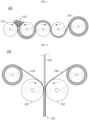
- the mixed powder for an electrode is introduced between a plurality of rolls to carry out calendering, thereby forming an electrode film.
- step 100 of forming an electrode film is illustrated, wherein a plurality of rolls 110 is disposed while being spaced apart from each other.
- the mixed powder 120 for an electrode obtained from the preceding step is introduced between the adjacent rolls 110, and the rolls 110 are rotated in the opposite direction.
- the mixed powder 120 is pressed, and then is subjected to a powder sheeting step so that it may be molded into a sheet or a film.
- calendering is carried out many times to obtain an electrode film having a final target thickness.
- the calendering includes processing the mixed powder for an electrode into the shape of a film.
- the mixed powder for an electrode may be molded into a film having an average thickness of 50-300 ⁇ m.
- the calendering may be carried out by using rolls facing each other, wherein the roll temperature may be 50-200°C and the roll rotation speed ratio may be controlled to a range of 1.0-2.0.
- a dry electrode film functioning as an electrode mixture may be obtained.
- the dry electrode film may also be called a free-standing film according to the related art.
- the resultant dry electrode film includes no solvent and has little flowability, and thus can be handled with ease and processed into a desired shape to be used for manufacturing electrodes with various shapes.
- a drying step for removing a solvent can be eliminated, and thus the production processability of the electrode can be improved significantly, and the problems of the methods for manufacturing a dry electrode according to the related art, such as the brittleness of an active material or cutting of a fibrilized fluorine-containing binder, can be solved.
- the dry electrode film may have a porosity of 20 ⁇ 50%.
- the porosity may be controlled preferably to a value of 40% or less, or 30% or less.
- the porosity satisfies the above-defined range, it is possible to facilitate wetting with an electrolyte, resulting in improvement of life characteristics, output characteristics, or the like.
- energy density based on volume can be improved, since the volume required to realize the same capacity is not increased.
- a method for manufacturing an electrode including a step of laminating the electrode film according to an embodiment of the present disclosure on a current collector.
- the lamination step may be a step of pressing and adhering the electrode film obtained by the method for manufacturing the electrode film according to an embodiment of the present disclosure onto a current collector to a desired thickness.
- the lamination may also be carried out by using a lamination roll, wherein the lamination roll may be maintained at a temperature of 25-250°C.
- the electrode film may have a compression ratio of 30-50%, 35-50%, or 40-50%.
- the lamination step may be controlled to satisfy a specific compression ratio. In this manner, it is possible to provide the electrode film with adequate density and porosity, and to realize excellent adhesion between the electrode film and the current collector.
- the pressure applied to the electrode film is sufficient so that the adhesion between the electrode film and the current collector may be improved.
- the compression ratio (%) of Formula 1 may be expressed by the following Formula 2: 30 ⁇ T 1 + 0.5 T c ⁇ 0.5 T gap / T 1 ⁇ 100 ⁇ 50 wherein T 1 represents the thickness of an electrode film before the lamination step, T c represents the thickness of a current collector, and T gap represents an interval between a first pressing roll and a second pressing roll.
- the electrode film subjected to the lamination step may have a pressing ratio of 20% or less, 18% or less, 15% or less, 5-15%, 6-15%, 7-15%, or 9-13%.
- the pressing ratio satisfies the above-defined range, it is possible to provide the resultant electrode film with adequate density and porosity, and to realize excellent adhesion between the electrode film and the current collector.
- the electrode film may have an increase in apparent density of 5-30%, 7-25%, or 10-20%, before and after its lamination with the current collector.
- each of D 1 and D 2 may range from 2.75 g/cm 3 to 3.5 g/cm 3 . Meanwhile, when the electrode film satisfies the above-defined range of an increase in apparent density, it is possible to improve the adhesion between the electrode film and the current collector and to prevent the problem of a porosity beyond the target range or damages to the positive electrode active material or current collector.
- Such an increase in apparent density before and after the lamination of the electrode film with the current collector may be calculated by measuring the weight and thickness of the electrode film before lamination, measuring the weight and thickness of the electrode after lamination, and calculating the weight and thickness of the film from which the weight and thickness of the current collector are subtracted.
- the dry electrode film may have an active material loading amount of 3-15 mAh/cm 2 , particularly 4-10 mAh/cm 2 .
- the interfacial resistance between the dry electrode film and the current collector may be 5 ⁇ cm 2 or less, particularly 2 ⁇ cm 2 or less.
- the interfacial resistance may be calculated by determining the resistance value between the dry electrode film and the current collector layer as a potential difference measured among multiple probes, after applying an electric current of 100 ⁇ A to the electrode through the multiprobe (MP) resistance test method.
- MP multiprobe
- FIG. 2 is a schematic view illustrating the step of laminating an electrode film on both surfaces of a current collector according to an embodiment of the present disclosure.
- the electrode film 230 obtained from the preceding step may be pressed on and attached to a current collector 220 to a desired thickness by using a pair of lamination rolls 210, thereby providing a finished electrode 240.
- a dry electrode obtained by the method for manufacturing a dry electrode.
- a secondary battery including the dry electrode, wherein the dry electrode is a positive electrode and including an electrode assembly including a positive electrode, a negative electrode and a separator and received in a battery casing (cylindrical casing, prismatic casing, pouch, or the like) together with a lithium-containing nonaqueous electrolyte.
- an energy storage system including the secondary battery as a unit cell.
- a system for manufacturing a dry electrode includes: a blender configured to mix ingredients of an electrode mixture including an active material, a conductive material and a fluorine-containing binder; a kneader configured to knead the mixture of the ingredients to form mixture lumps; a pulverizer configured to pulverize the mixture lumps to form a mixed powder for an electrode; a calender configured to form a dry electrode film from the mixed powder for an electrode; and a lamination roll configured to dispose the dry electrode film on at least one surface of a current collector and to carry out lamination.
- the blender is a mixer configured to mix the ingredients. As described above, the ingredients of the mixture may be mixed at a rate of 5,000-20,000 rpm.
- the kneader is a device for fibrilizing a fluorine-containing binder and dispersing the ingredients of the mixture according to the present disclosure, and the mixture may be obtained in the form of mixture lumps through the kneading in the kneader.
- the kneader may be set to a temperature of 70-200°C and a pressure condition equal to or higher than ambient pressure.
- the kneader may be set to a temperature of 90-180°C and a pressure condition of 1-100 atm, more particularly 10-80 atm.
- the pulverizer is configured to pulverize the obtained mixture lumps to form a mixed powder for an electrode, and may include a blender or a grinder.
- the calender is a device for molding the mixed powder for an electrode into a film shape.
- the calender may include a pair of rollers facing each other, and the film thickness may be controlled from the interval between the rollers.
- the lamination roll functions to attach the dry electrode film formed by the calender to at least one surface of the current collector and to carry out pressing.
- the porosity of the dry electrode film according to the present disclosure may be determined by the calender and the lamination roll.
- the system for manufacturing a dry electrode according to the present disclosure is characterized by including a kneader and a pulverizer.
- LiFePO 4 lithium iron phosphate
- carbon black as a conductive material
- PTFE polytetrafluoroethylene
- the mixture lumps were introduced to a blender, pulverized at 10,000 rpm for 1 minute, and classified by using a sieve having pores with a size of 1 mm to obtain a mixed powder for an electrode. Then, the resultant mixed powder for an electrode was introduced to a lab calender (roll diameter: 160 mm, roll temperature: 100°C) to obtain an electrode film. The resultant electrode film had a thickness of 80 ⁇ m.
- An electrode film was obtained in the same manner as Comparative Example 1, except that polytetrafluoroethylene (PTFE) as a fluorine-containing binder was heat treated by using a furnace at the heat treatment temperature and for the heat treatment time as shown in the following Table 1 under the atmosphere of air and then cooled to room temperature (25°C).
- PTFE polytetrafluoroethylene
- An electrode film was obtained in the same manner as Comparative Example 1, except that 87 g of lithium iron phosphate (LFP, LiFePO 4 ) as a positive electrode active material, 1 g of carbon black as a conductive material and 12 g of polytetrafluoroethylene (PTFE) as a fluorine-containing binder were used, and polytetrafluoroethylene (PTFE) was heat treated by using a furnace at the heat treatment temperature and for the heat treatment time as shown in the following Table 1 under the atmosphere of air and then cooled to room temperature (25°C).
- LFP lithium iron phosphate
- LiFePO 4 lithium iron phosphate
- carbon black as a conductive material
- PTFE polytetrafluoroethylene
- PTFE polytetrafluoroethylene
- the elongation at break of each electrode film was determined by using a UTM instrument (ZwickRoell Co.) under the following test conditions.
- Test Conditions ASTM D 638, Pre-load 0.01 kg/cm, Test Speed 50 mm/min.
- the modulus of each electrode film was determined by using a UTM instrument (ZwickRoell Co.) under the following test conditions.
- Test Conditions ASTM D 638, Pre-load 0.01 kg/cm, Test Speed 50 mm/min.
- the tensile strength of each electrode film was determined by using a UTM instrument (ZwickRoell Co.) under the following test conditions.
- Test Conditions ASTM D 638, Pre-load 0.01 kg/cm, Test Speed 50 mm/min.
- the electrode films obtained by heat treating the fluorine-containing binder at 290-310°C and mixing the heat treated fluorine-containing binder with an active material, or the like, according to Examples 1-3 show significantly improved mechanical properties, including elongation at break, modulus and tensile strength, as compared to the electrode films, using no heat treatment or not satisfying the above-defined heat treatment temperature condition, according to Comparative Examples 1-3.
- the electrode film according to Comparative Example 4 satisfies the condition of elongation at break (3.5% or more), it includes the fluorine-containing binder in an amount of 12 parts by weight based on 100 parts by weight of the total weight of the electrode film. Therefore, in the case of Comparative Example 4, since the content of fluorine-containing binder does not fall within the range of 0.5-10 parts by weight based on 100 parts by weight of the total weight of the electrode film, the electrode film shows a significantly low tensile strength.
Landscapes
- Chemical & Material Sciences (AREA)
- Chemical Kinetics & Catalysis (AREA)
- Electrochemistry (AREA)
- General Chemical & Material Sciences (AREA)
- Engineering & Computer Science (AREA)
- Manufacturing & Machinery (AREA)
- Materials Engineering (AREA)
- Inorganic Chemistry (AREA)
- Crystallography & Structural Chemistry (AREA)
- Composite Materials (AREA)
- Battery Electrode And Active Subsutance (AREA)
- Cell Electrode Carriers And Collectors (AREA)
Applications Claiming Priority (2)
| Application Number | Priority Date | Filing Date | Title |
|---|---|---|---|
| KR20220049211 | 2022-04-20 | ||
| PCT/KR2023/005415 WO2023204648A1 (ko) | 2022-04-20 | 2023-04-20 | 전극용 필름, 이를 포함하는 전극, 이차전지, 및 이의 제조 방법 |
Publications (2)
| Publication Number | Publication Date |
|---|---|
| EP4503177A1 true EP4503177A1 (de) | 2025-02-05 |
| EP4503177A4 EP4503177A4 (de) | 2025-12-31 |
Family
ID=88420209
Family Applications (2)
| Application Number | Title | Priority Date | Filing Date |
|---|---|---|---|
| EP23792219.0A Pending EP4503176A4 (de) | 2022-04-20 | 2023-04-20 | Folie für elektrode, elektrode damit, sekundärbatterie und verfahren zur herstellung davon |
| EP23792222.4A Pending EP4503177A4 (de) | 2022-04-20 | 2023-04-20 | Folie für elektrode, elektrode damit, sekundärbatterie und verfahren zur herstellung davon |
Family Applications Before (1)
| Application Number | Title | Priority Date | Filing Date |
|---|---|---|---|
| EP23792219.0A Pending EP4503176A4 (de) | 2022-04-20 | 2023-04-20 | Folie für elektrode, elektrode damit, sekundärbatterie und verfahren zur herstellung davon |
Country Status (6)
| Country | Link |
|---|---|
| US (1) | US20250279423A1 (de) |
| EP (2) | EP4503176A4 (de) |
| JP (2) | JP2025512004A (de) |
| KR (4) | KR102875079B1 (de) |
| CN (2) | CN119054102A (de) |
| WO (2) | WO2023204645A1 (de) |
Families Citing this family (3)
| Publication number | Priority date | Publication date | Assignee | Title |
|---|---|---|---|---|
| WO2025197691A1 (ja) * | 2024-03-22 | 2025-09-25 | パナソニックIpマネジメント株式会社 | 電極の製造方法、及び電極 |
| CN119833574B (zh) * | 2025-01-07 | 2025-10-28 | 中自科技股份有限公司 | 一种含复合纳米碳化硅的钠离子电池极片及其制备方法 |
| CN120058997B (zh) * | 2025-04-25 | 2025-07-04 | 浙江省白马湖实验室有限公司 | 一种用于干法电极的粘结剂预处理方法及其应用 |
Family Cites Families (21)
| Publication number | Priority date | Publication date | Assignee | Title |
|---|---|---|---|---|
| KR100201056B1 (ko) * | 1994-10-19 | 1999-06-15 | 이노우에 노리유끼 | 전지용 결착제 및 이를 사용한 전극용 조성물 및 전지 |
| JP4059556B2 (ja) * | 1998-03-26 | 2008-03-12 | 三洋電機株式会社 | 非水電解液電池およびその製造方法 |
| JP2001266854A (ja) * | 2000-03-22 | 2001-09-28 | Matsushita Electric Ind Co Ltd | 非水電解液二次電池用電極の製造法 |
| JP4931383B2 (ja) * | 2005-07-20 | 2012-05-16 | 大同メタル工業株式会社 | 二次電池用電極 |
| JP4560079B2 (ja) * | 2007-08-09 | 2010-10-13 | パナソニック株式会社 | 非水電解質二次電池用正極の製造方法 |
| CN102171861A (zh) * | 2009-03-16 | 2011-08-31 | 松下电器产业株式会社 | 非水电解质二次电池用电极板及其制造方法及非水电解质二次电池 |
| KR101696902B1 (ko) * | 2013-08-26 | 2017-01-17 | 삼성전자주식회사 | 활물질, 그 제조방법, 이를 포함하는 전극 및 이를 포함한 이차 전지 |
| US9887419B2 (en) * | 2013-08-26 | 2018-02-06 | Samsung Electronics Co., Ltd. | Active material, method of preparing the active material electrode including the active material, and secondary battery including the electrode |
| JP2016207583A (ja) * | 2015-04-27 | 2016-12-08 | 株式会社カネカ | 二次電池電極用のシート状活物質粒子含有成形体、二次電池用電極、およびそれを用いた二次電池。 |
| KR102559757B1 (ko) * | 2016-03-01 | 2023-07-27 | 테슬라, 인크. | 에너지 저장 장치를 위한 전극 및 건식 에너지 저장 장치 전극 필름을 제조하기 위한 방법 |
| US10847780B2 (en) * | 2016-09-16 | 2020-11-24 | Pacesetter, Inc. | Battery electrode and methods of making |
| US11276846B2 (en) * | 2017-09-25 | 2022-03-15 | Lg Energy Solution, Ltd. | Method for manufacturing electrode for secondary battery and electrode manufactured thereby |
| CN114284632B (zh) * | 2018-04-11 | 2024-04-05 | 宁德新能源科技有限公司 | 隔离膜及储能装置 |
| US20210155766A1 (en) * | 2018-04-13 | 2021-05-27 | Navitas Systems, Llc | Compositions and methods for electrode fabrication |
| WO2019208806A1 (ja) * | 2018-04-27 | 2019-10-31 | 株式会社村田製作所 | 電池 |
| CN112424973A (zh) * | 2018-05-14 | 2021-02-26 | 麦斯韦尔技术股份有限公司 | 用于具有减少的粘合剂含量的干电极膜的组合物和方法 |
| US11616218B2 (en) * | 2019-06-04 | 2023-03-28 | Licap Technologies, Inc. | Dry electrode manufacture by temperature activation method |
| CN112349874B (zh) * | 2019-08-08 | 2021-11-09 | 宁德时代新能源科技股份有限公司 | 正极极片及锂离子电池 |
| WO2022024520A1 (ja) * | 2020-07-31 | 2022-02-03 | パナソニックIpマネジメント株式会社 | Ptfe粉末、電極の製造方法、及び電極 |
| KR102402387B1 (ko) | 2020-10-14 | 2022-05-26 | 주식회사 효진엔지니어링 | 폐가스 처리 스크러버용 조립식 기액접촉수단 단위체 및 이를 이용한 폐가스 처리 스크러버 |
| KR102877744B1 (ko) * | 2021-08-06 | 2025-10-27 | 주식회사 엘지에너지솔루션 | 건식 전극 필름 제조 방법 및 상기 전극 필름 제조 시스템 |
-
2023
- 2023-04-20 WO PCT/KR2023/005412 patent/WO2023204645A1/ko not_active Ceased
- 2023-04-20 EP EP23792219.0A patent/EP4503176A4/de active Pending
- 2023-04-20 CN CN202380035100.5A patent/CN119054102A/zh active Pending
- 2023-04-20 JP JP2024559922A patent/JP2025512004A/ja active Pending
- 2023-04-20 KR KR1020230052337A patent/KR102875079B1/ko active Active
- 2023-04-20 CN CN202380035101.XA patent/CN119137764A/zh active Pending
- 2023-04-20 EP EP23792222.4A patent/EP4503177A4/de active Pending
- 2023-04-20 JP JP2024559921A patent/JP2025512003A/ja active Pending
- 2023-04-20 US US18/857,728 patent/US20250279423A1/en active Pending
- 2023-04-20 WO PCT/KR2023/005415 patent/WO2023204648A1/ko not_active Ceased
- 2023-04-20 KR KR1020230052335A patent/KR102838158B1/ko active Active
-
2025
- 2025-07-21 KR KR1020250098149A patent/KR20250113977A/ko active Pending
- 2025-10-17 KR KR1020250150891A patent/KR20250156057A/ko active Pending
Also Published As
| Publication number | Publication date |
|---|---|
| KR20250113977A (ko) | 2025-07-28 |
| WO2023204645A1 (ko) | 2023-10-26 |
| CN119054102A (zh) | 2024-11-29 |
| KR102875079B1 (ko) | 2025-10-22 |
| US20250279423A1 (en) | 2025-09-04 |
| JP2025512004A (ja) | 2025-04-16 |
| JP2025512003A (ja) | 2025-04-16 |
| CN119137764A (zh) | 2024-12-13 |
| KR20250156057A (ko) | 2025-10-31 |
| KR20230149761A (ko) | 2023-10-27 |
| EP4503176A4 (de) | 2025-04-23 |
| EP4503177A4 (de) | 2025-12-31 |
| KR20230149760A (ko) | 2023-10-27 |
| EP4503176A1 (de) | 2025-02-05 |
| WO2023204648A1 (ko) | 2023-10-26 |
| KR102838158B1 (ko) | 2025-07-24 |
Similar Documents
| Publication | Publication Date | Title |
|---|---|---|
| EP4216298B1 (de) | Pulver für elektrode zur herstellung einer trockenelektrode für eine sekundärbatterie, verfahren zu deren herstellung, verfahren zur herstellung einer trockenelektrode unter verwendung desselben, trockenelektrode, sekundärbatterie mit derselben, energiespeichervorrichtung und vorrichtung | |
| EP4152445B1 (de) | Elektrode für elektrochemische vorrichtung, die eine trockenelektrodenfolie umfasst, und herstellungsverfahren zdafür | |
| EP4503177A1 (de) | Folie für elektrode, elektrode damit, sekundärbatterie und verfahren zur herstellung davon | |
| EP4318650A1 (de) | Herstellungssystem und verfahren für trockene elektrodenfolie | |
| EP4465407A1 (de) | Elektrodenanordnung und sekundärbatterie damit | |
| CA3227840A1 (en) | Electrode for electrochemical device comprising dry electrode film and method for manufacturing same | |
| US20230114069A1 (en) | Method of manufacturing an electrode comprising a dry electrode film and an electrode for an electrochemical device therefrom | |
| EP4503200B1 (de) | Masterbatch aus leitfähigem material und unter verwendung davon hergestellte trockenelektrode | |
| CN118805269A (zh) | 用于干电极的混合物粉末和包括该混合物粉末的用于电化学装置的干电极 | |
| US20250183313A1 (en) | Electrode, Secondary Battery Comprising the Same, and Method for Manufacturing the Same | |
| EP4513583A1 (de) | Elektrode, sekundärbatterie damit und verfahren zur herstellung davon | |
| KR20230128215A (ko) | 전극용 필름, 이를 포함하는 전극, 이를 포함하는 이차전지, 및 이의 제조 방법 |
Legal Events
| Date | Code | Title | Description |
|---|---|---|---|
| STAA | Information on the status of an ep patent application or granted ep patent |
Free format text: STATUS: THE INTERNATIONAL PUBLICATION HAS BEEN MADE |
|
| PUAI | Public reference made under article 153(3) epc to a published international application that has entered the european phase |
Free format text: ORIGINAL CODE: 0009012 |
|
| STAA | Information on the status of an ep patent application or granted ep patent |
Free format text: STATUS: REQUEST FOR EXAMINATION WAS MADE |
|
| 17P | Request for examination filed |
Effective date: 20241031 |
|
| AK | Designated contracting states |
Kind code of ref document: A1 Designated state(s): AL AT BE BG CH CY CZ DE DK EE ES FI FR GB GR HR HU IE IS IT LI LT LU LV MC ME MK MT NL NO PL PT RO RS SE SI SK SM TR |
|
| DAV | Request for validation of the european patent (deleted) | ||
| DAX | Request for extension of the european patent (deleted) | ||
| A4 | Supplementary search report drawn up and despatched |
Effective date: 20251202 |
|
| RIC1 | Information provided on ipc code assigned before grant |
Ipc: H01M 4/1391 20100101AFI20251126BHEP Ipc: H01M 4/525 20100101ALI20251126BHEP Ipc: H01M 4/58 20100101ALI20251126BHEP Ipc: H01M 4/62 20060101ALI20251126BHEP Ipc: H01M 4/66 20060101ALI20251126BHEP Ipc: H01M 4/04 20060101ALI20251126BHEP Ipc: H01M 4/131 20100101ALI20251126BHEP Ipc: H01M 4/136 20100101ALI20251126BHEP Ipc: H01M 4/1397 20100101ALI20251126BHEP Ipc: H01M 4/02 20060101ALN20251126BHEP Ipc: H01M 10/0525 20100101ALN20251126BHEP |