EP4503221A1 - Endkappenanordnung, batteriezelle, batterie und elektrische vorrichtung - Google Patents
Endkappenanordnung, batteriezelle, batterie und elektrische vorrichtung Download PDFInfo
- Publication number
- EP4503221A1 EP4503221A1 EP22956368.9A EP22956368A EP4503221A1 EP 4503221 A1 EP4503221 A1 EP 4503221A1 EP 22956368 A EP22956368 A EP 22956368A EP 4503221 A1 EP4503221 A1 EP 4503221A1
- Authority
- EP
- European Patent Office
- Prior art keywords
- end cover
- electrode terminal
- lead
- out hole
- battery cell
- Prior art date
- Legal status (The legal status is an assumption and is not a legal conclusion. Google has not performed a legal analysis and makes no representation as to the accuracy of the status listed.)
- Pending
Links
Images


Classifications
-
- H—ELECTRICITY
- H01—ELECTRIC ELEMENTS
- H01M—PROCESSES OR MEANS, e.g. BATTERIES, FOR THE DIRECT CONVERSION OF CHEMICAL ENERGY INTO ELECTRICAL ENERGY
- H01M50/00—Constructional details or processes of manufacture of the non-active parts of electrochemical cells other than fuel cells, e.g. hybrid cells
- H01M50/10—Primary casings; Jackets or wrappings
- H01M50/172—Arrangements of electric connectors penetrating the casing
-
- H—ELECTRICITY
- H01—ELECTRIC ELEMENTS
- H01M—PROCESSES OR MEANS, e.g. BATTERIES, FOR THE DIRECT CONVERSION OF CHEMICAL ENERGY INTO ELECTRICAL ENERGY
- H01M50/00—Constructional details or processes of manufacture of the non-active parts of electrochemical cells other than fuel cells, e.g. hybrid cells
- H01M50/10—Primary casings; Jackets or wrappings
- H01M50/147—Lids or covers
- H01M50/148—Lids or covers characterised by their shape
- H01M50/15—Lids or covers characterised by their shape for prismatic or rectangular cells
-
- H—ELECTRICITY
- H01—ELECTRIC ELEMENTS
- H01M—PROCESSES OR MEANS, e.g. BATTERIES, FOR THE DIRECT CONVERSION OF CHEMICAL ENERGY INTO ELECTRICAL ENERGY
- H01M10/00—Secondary cells; Manufacture thereof
- H01M10/05—Accumulators with non-aqueous electrolyte
- H01M10/052—Li-accumulators
- H01M10/0525—Rocking-chair batteries, i.e. batteries with lithium insertion or intercalation in both electrodes; Lithium-ion batteries
-
- H—ELECTRICITY
- H01—ELECTRIC ELEMENTS
- H01M—PROCESSES OR MEANS, e.g. BATTERIES, FOR THE DIRECT CONVERSION OF CHEMICAL ENERGY INTO ELECTRICAL ENERGY
- H01M50/00—Constructional details or processes of manufacture of the non-active parts of electrochemical cells other than fuel cells, e.g. hybrid cells
- H01M50/10—Primary casings; Jackets or wrappings
- H01M50/147—Lids or covers
- H01M50/166—Lids or covers characterised by the methods of assembling casings with lids
- H01M50/169—Lids or covers characterised by the methods of assembling casings with lids by welding, brazing or soldering
-
- H—ELECTRICITY
- H01—ELECTRIC ELEMENTS
- H01M—PROCESSES OR MEANS, e.g. BATTERIES, FOR THE DIRECT CONVERSION OF CHEMICAL ENERGY INTO ELECTRICAL ENERGY
- H01M50/00—Constructional details or processes of manufacture of the non-active parts of electrochemical cells other than fuel cells, e.g. hybrid cells
- H01M50/10—Primary casings; Jackets or wrappings
- H01M50/172—Arrangements of electric connectors penetrating the casing
- H01M50/174—Arrangements of electric connectors penetrating the casing adapted for the shape of the cells
- H01M50/176—Arrangements of electric connectors penetrating the casing adapted for the shape of the cells for prismatic or rectangular cells
-
- H—ELECTRICITY
- H01—ELECTRIC ELEMENTS
- H01M—PROCESSES OR MEANS, e.g. BATTERIES, FOR THE DIRECT CONVERSION OF CHEMICAL ENERGY INTO ELECTRICAL ENERGY
- H01M50/00—Constructional details or processes of manufacture of the non-active parts of electrochemical cells other than fuel cells, e.g. hybrid cells
- H01M50/10—Primary casings; Jackets or wrappings
- H01M50/183—Sealing members
- H01M50/186—Sealing members characterised by the disposition of the sealing members
- H01M50/188—Sealing members characterised by the disposition of the sealing members the sealing members being arranged between the lid and terminal
-
- H—ELECTRICITY
- H01—ELECTRIC ELEMENTS
- H01M—PROCESSES OR MEANS, e.g. BATTERIES, FOR THE DIRECT CONVERSION OF CHEMICAL ENERGY INTO ELECTRICAL ENERGY
- H01M50/00—Constructional details or processes of manufacture of the non-active parts of electrochemical cells other than fuel cells, e.g. hybrid cells
- H01M50/50—Current conducting connections for cells or batteries
- H01M50/502—Interconnectors for connecting terminals of adjacent batteries; Interconnectors for connecting cells outside a battery casing
-
- H—ELECTRICITY
- H01—ELECTRIC ELEMENTS
- H01M—PROCESSES OR MEANS, e.g. BATTERIES, FOR THE DIRECT CONVERSION OF CHEMICAL ENERGY INTO ELECTRICAL ENERGY
- H01M50/00—Constructional details or processes of manufacture of the non-active parts of electrochemical cells other than fuel cells, e.g. hybrid cells
- H01M50/50—Current conducting connections for cells or batteries
- H01M50/528—Fixed electrical connections, i.e. not intended for disconnection
-
- H—ELECTRICITY
- H01—ELECTRIC ELEMENTS
- H01M—PROCESSES OR MEANS, e.g. BATTERIES, FOR THE DIRECT CONVERSION OF CHEMICAL ENERGY INTO ELECTRICAL ENERGY
- H01M50/00—Constructional details or processes of manufacture of the non-active parts of electrochemical cells other than fuel cells, e.g. hybrid cells
- H01M50/50—Current conducting connections for cells or batteries
- H01M50/531—Electrode connections inside a battery casing
-
- H—ELECTRICITY
- H01—ELECTRIC ELEMENTS
- H01M—PROCESSES OR MEANS, e.g. BATTERIES, FOR THE DIRECT CONVERSION OF CHEMICAL ENERGY INTO ELECTRICAL ENERGY
- H01M50/00—Constructional details or processes of manufacture of the non-active parts of electrochemical cells other than fuel cells, e.g. hybrid cells
- H01M50/50—Current conducting connections for cells or batteries
- H01M50/543—Terminals
- H01M50/547—Terminals characterised by the disposition of the terminals on the cells
- H01M50/55—Terminals characterised by the disposition of the terminals on the cells on the same side of the cell
-
- H—ELECTRICITY
- H01—ELECTRIC ELEMENTS
- H01M—PROCESSES OR MEANS, e.g. BATTERIES, FOR THE DIRECT CONVERSION OF CHEMICAL ENERGY INTO ELECTRICAL ENERGY
- H01M50/00—Constructional details or processes of manufacture of the non-active parts of electrochemical cells other than fuel cells, e.g. hybrid cells
- H01M50/50—Current conducting connections for cells or batteries
- H01M50/543—Terminals
- H01M50/564—Terminals characterised by their manufacturing process
- H01M50/566—Terminals characterised by their manufacturing process by welding, soldering or brazing
-
- H—ELECTRICITY
- H01—ELECTRIC ELEMENTS
- H01M—PROCESSES OR MEANS, e.g. BATTERIES, FOR THE DIRECT CONVERSION OF CHEMICAL ENERGY INTO ELECTRICAL ENERGY
- H01M50/00—Constructional details or processes of manufacture of the non-active parts of electrochemical cells other than fuel cells, e.g. hybrid cells
- H01M50/50—Current conducting connections for cells or batteries
- H01M50/572—Means for preventing undesired use or discharge
- H01M50/584—Means for preventing undesired use or discharge for preventing incorrect connections inside or outside the batteries
- H01M50/586—Means for preventing undesired use or discharge for preventing incorrect connections inside or outside the batteries inside the batteries, e.g. incorrect connections of electrodes
-
- H—ELECTRICITY
- H01—ELECTRIC ELEMENTS
- H01M—PROCESSES OR MEANS, e.g. BATTERIES, FOR THE DIRECT CONVERSION OF CHEMICAL ENERGY INTO ELECTRICAL ENERGY
- H01M50/00—Constructional details or processes of manufacture of the non-active parts of electrochemical cells other than fuel cells, e.g. hybrid cells
- H01M50/50—Current conducting connections for cells or batteries
- H01M50/572—Means for preventing undesired use or discharge
- H01M50/584—Means for preventing undesired use or discharge for preventing incorrect connections inside or outside the batteries
- H01M50/59—Means for preventing undesired use or discharge for preventing incorrect connections inside or outside the batteries characterised by the protection means
- H01M50/593—Spacers; Insulating plates
-
- H—ELECTRICITY
- H01—ELECTRIC ELEMENTS
- H01M—PROCESSES OR MEANS, e.g. BATTERIES, FOR THE DIRECT CONVERSION OF CHEMICAL ENERGY INTO ELECTRICAL ENERGY
- H01M10/00—Secondary cells; Manufacture thereof
- H01M10/05—Accumulators with non-aqueous electrolyte
- H01M10/054—Accumulators with insertion or intercalation of metals other than lithium, e.g. with magnesium or aluminium
-
- H—ELECTRICITY
- H01—ELECTRIC ELEMENTS
- H01M—PROCESSES OR MEANS, e.g. BATTERIES, FOR THE DIRECT CONVERSION OF CHEMICAL ENERGY INTO ELECTRICAL ENERGY
- H01M10/00—Secondary cells; Manufacture thereof
- H01M10/05—Accumulators with non-aqueous electrolyte
- H01M10/058—Construction or manufacture
-
- H—ELECTRICITY
- H01—ELECTRIC ELEMENTS
- H01M—PROCESSES OR MEANS, e.g. BATTERIES, FOR THE DIRECT CONVERSION OF CHEMICAL ENERGY INTO ELECTRICAL ENERGY
- H01M6/00—Primary cells; Manufacture thereof
- H01M6/14—Cells with non-aqueous electrolyte
-
- Y—GENERAL TAGGING OF NEW TECHNOLOGICAL DEVELOPMENTS; GENERAL TAGGING OF CROSS-SECTIONAL TECHNOLOGIES SPANNING OVER SEVERAL SECTIONS OF THE IPC; TECHNICAL SUBJECTS COVERED BY FORMER USPC CROSS-REFERENCE ART COLLECTIONS [XRACs] AND DIGESTS
- Y02—TECHNOLOGIES OR APPLICATIONS FOR MITIGATION OR ADAPTATION AGAINST CLIMATE CHANGE
- Y02E—REDUCTION OF GREENHOUSE GAS [GHG] EMISSIONS, RELATED TO ENERGY GENERATION, TRANSMISSION OR DISTRIBUTION
- Y02E60/00—Enabling technologies; Technologies with a potential or indirect contribution to GHG emissions mitigation
- Y02E60/10—Energy storage using batteries
Definitions
- This application relates to the field of battery technologies, and in particular, to an end cover assembly, a battery cell, a battery, and an electric apparatus.
- a traction battery includes a battery cell, and an adapting component of the battery cell is fixed to an electrode terminal by welding. Residual metal shavings during welding are prone to increasing safety hazards of the battery cell.
- this application provides an end cover assembly, a battery cell, a battery, and an electric apparatus, so as to reduce safety risks caused by residual metal shavings.
- a first aspect of this application proposes an end cover assembly applied to a battery cell, where the end cover assembly includes:
- the adapting component that facilitates removal of metal shavings can be used when the electrode terminal is fixed to the adapting component by welding, reducing residual metal shavings after welding, thereby reducing safety risks caused by the residual metal shavings.
- a lower surface of the end cover in an axial direction of the lead-out hole, has a first region opposite the adapting component, the adapting component and the first region being spaced apart.
- the adapting component and the first region being spaced apart can avoid interference between the adapting component and the end cover, improving stability of welding between the adapting component and the electrode terminal.
- a distance between the adapting component and the first region is L, where 0 mm ⁇ L ⁇ 0.3 mm.
- the distance between the adapting component and the lower surface is greater than 0 mm and less than or equal to 0.3 mm, the adapting component and the lower surface can be spaced apart, so as to reduce transfer of welding heat to the end cover, reducing adverse effects of the welding heat on the end cover.
- an extension height of the bottom surface is T, where T ⁇ [0.05 mm, 1 mm].
- the value of the extension height of the bottom surface of the electrode terminal relative to the lead-out hole is set in the range of [0.05 mm, 1 mm].
- the electrode terminal includes a terminal plate and an extension portion, where the terminal plate is located at a side of the end cover and covers the lead-out hole, the end cover assembly further includes a sealing ring, at least a portion of the sealing ring is located between the terminal plate and the end cover to seal the lead-out hole, the extension portion extends into the lead-out hole, and in a radial direction of the lead-out hole, a distance between the extension portion and the sealing ring is k, where k ⁇ [1.5 mm, 2.5 mm].
- the provision of the sealing ring achieves the sealing of the lead-out hole.
- the extension portion and the sealing ring being spaced apart reduces transfer of the welding heat to the sealing ring and reduces the adverse effects of the welding heat on the sealing ring, guaranteeing the sealing effect of the sealing ring.
- the sealing ring includes a first portion and a second portion, where the first portion is located between the terminal plate and the end cover, the second portion extends into the lead-out hole, and in the radial direction of the lead-out hole, a distance between the extension portion and the second portion is k, where k ⁇ [1.5 mm, 2.5 mm].
- the sealing ring being provided as the first portion and the second portion can improve the positioning effect of the sealing ring, thereby improving the sealing effect of the sealing ring.
- the extension portion is a cylindrical structure
- the sealing ring is an annular member, where a diameter of the cylindrical structure is d1, and an inner diameter of the annular member is d2, where d1/d2 ⁇ [0.75, 2.5].
- the extension portion being set as the cylindrical structure and the sealing ring being set as the annular member facilitate coaxial assembly of the sealing ring and the extension portion during mounting, improving the assembly accuracy of the sealing ring.
- a ratio of the diameter of the cylindrical structure to the inner diameter of the annular member being set in the range of [0.75, 2.5] allows for a sufficiently large cross section of the extension portion, so that the extension portion has a large current flow area after connected to the adapting component, reducing the situation that the performance of the battery cell is affected by heating at the connection position.
- the diameter d1 of the cylindrical structure is ⁇ [12 mm, 16 mm]
- the inner diameter d2 of the annular member is ⁇ [15.2 mm, 20 mm].
- the diameter of the cylindrical structure and the inner diameter of the annular member being set to the foregoing values further improves the mounting accuracy of the sealing ring, and allows for a large cross-sectional area of the extension portion of the cylindrical structure, further increasing the current flow area between the extension portion and the adapting component.
- the electrode terminal further includes:
- the terminal plate, the insulating member, the fixing member, and the end cover are connected in sequence to connect and fix the electrode terminal to the end cover.
- the insulating member is used to insulate the electrode terminal from the end cover, improving safety in use.
- the bottom surface is flat.
- the bottom surface of the electrode terminal being set to be flat increases a contact area between the electrode terminal and the adapting component that are connected, improves connection strength between the electrode terminal and the adapting component, and also increases the current flow area between the electrode terminal and the adapting component, thereby reducing the situation that the performance of the battery cell is affected by heating at the connection position.
- the end cover includes a top cover plate and an insulating plate, where the insulating plate is mounted at the bottom of the top cover plate, the lead-out hole passes through the top cover plate and the insulating plate, and the bottom surface of the electrode terminal extends beyond a surface of the insulating plate corresponding to the adapting component.
- the insulating plate can insulate and isolate the top cover plate from the adapting component.
- a second aspect of this application proposes a battery cell including:
- the adapting component is a flat plate structure, which can facilitate removal of metal shavings and manufacturing.
- a side of the adapting component facing the electrode terminal is provided with a recess, a portion of the electrode terminal is accommodated in the recess, and the adapting component is flat at a side back away from the electrode terminal or is provided with a protrusion at a position corresponding to the recess. This facilitates removal of the metal shavings. This can also improve compactness of the internal structure of the battery cell.
- the battery cell further includes a cell assembly, where the cell assembly includes a body portion and a tab, the adapting component connects the tab and the electrode terminal, and thickness of a portion at which the adapting component is welded to the electrode terminal is M; and in an axial direction of the lead-out hole, a lower surface of the end cover has a first region opposite the adapting component, where a distance from the first region to the cell assembly is D, and an extension height of the bottom surface is T, where T ⁇ (D - M).
- the cell assembly includes a body portion and a tab
- the adapting component connects the tab and the electrode terminal, and thickness of a portion at which the adapting component is welded to the electrode terminal is M; and in an axial direction of the lead-out hole, a lower surface of the end cover has a first region opposite the adapting component, where a distance from the first region to the cell assembly is D, and an extension height of the bottom surface is T, where T ⁇ (D - M).
- a third aspect of this application proposes a battery including the battery cell as described above.
- a fourth aspect of this application proposes an electric apparatus, where the electric apparatus includes the battery cell as described above.
- the term "and/or" is only an associative relationship for describing associated objects, indicating that three relationships may be present.
- a and/or B may indicate the following three cases: presence of only A, presence of both A and B, and presence of only B.
- the character "/" in this specification generally indicates an "or" relationship between the contextually associated objects.
- a plurality of means more than two (inclusive).
- a plurality of groups means more than two (inclusive) groups
- a plurality of pieces means more than two (inclusive) pieces.
- mount should be understood in their general senses. For example, they may refer to a fixed connection, a detachable connection, or an integral connection, may refer to a mechanical connection or an electrical connection, and may refer to a direct connection, an indirect connection via an intermediate medium, an internal communication between two elements, or an interaction between two elements. Persons of ordinary skill in the art can understand specific meanings of these terms in the embodiments of this application as appropriate to specific situations.
- Traction batteries have been widely used in energy storage power supply systems such as hydroelectric power plants, thermal power plants, wind power plants, and solar power plants, and many other fields including electric transportation tools such as electric bicycles, electric motorcycles, and electric vehicles, military equipment, and aerospace. With the continuous expansion of application fields of traction batteries, market demands for traction batteries are also increasing.
- a battery cell of a traction battery has an electrode terminal, a cell, and an adapting component, where the electrode terminal is electrically connected to a tab of the cell through the adapting component.
- the adapting component is fixed to the electrode terminal by welding.
- metal shavings are prone to remaining during welding, and the residual metal shavings easily lead to problems such as short circuit of the cell, increasing safety risks. Therefore, how safety risks caused by residual metal shavings are reduced has become a technical problem that needs to be solved urgently by persons skilled in the art.
- an adapting component that facilitates removal of the metal shavings can be used when the electrode terminal is fixed to the adapting component by welding, reducing the residual metal shavings after welding, thereby reducing the safety risks caused by the residual metal shavings.
- the battery cell disclosed in the embodiments of this application may be used without limitation in electric apparatus such as vehicles, ships, or aircrafts.
- the battery cell, battery, and the like disclosed in this application may be used to constitute a power supply system of that electric apparatus.
- An embodiment of this application provides an electric apparatus that uses a battery as a power source.
- the electric apparatus may be but is not limited to a mobile phone, a tablet, a notebook computer, an electric toy, an electric tool, an electric bicycle, an electric vehicle, a ship, or a spacecraft.
- the electric toy may include a fixed or mobile electric toy, for example, a game console, an electric toy car, an electric toy ship, and an electric toy airplane.
- the spacecraft may include an airplane, a rocket, a space shuttle, a spaceship, and the like.
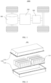
- FIG. 1 is a schematic structural diagram of a vehicle 1000 according to some embodiments of this application.
- the vehicle 1000 may be a fossil fuel vehicle, a natural gas vehicle, or a new energy vehicle.
- the new energy vehicle may be a battery electric vehicle, a hybrid electric vehicle, a range-extended electric vehicle, or the like.
- the vehicle 1000 is provided with a battery 100 inside, where the battery 100 may be disposed at the bottom, front, or rear of the vehicle 1000.
- the battery 100 may be configured to supply power to the vehicle 1000.
- the battery 100 may be used as an operational power source for the vehicle 1000.
- the vehicle 1000 may further include a controller 200 and a motor 300, where the controller 200 is configured to control the battery 100 to supply power to the motor 300, for example, to satisfy power needs of start, navigation, and driving of the vehicle 1000.
- the battery 100 can be used as not only the operational power source for the vehicle 1000 but also a driving power source for the vehicle 1000, replacing or partially replacing fossil fuel or natural gas to provide driving traction for the vehicle 1000.
- the battery 100 may include a plurality of battery cells.
- the battery cell is a smallest element constituting a battery 100 module or battery 100 pack.
- the plurality of battery cells can be connected in series and/or in parallel through electrode terminals for various application scenarios.
- the battery 100 mentioned in this application includes a battery 100 module or a battery 100 pack.
- the plurality of battery cells may be connected in series, parallel, or series-parallel, where being connected in series-parallel means a combination of series and parallel connections.
- the battery 100 may also be referred to as a battery 100 pack.
- the plurality of battery cells may be directly combined into a battery pack, or they may be first combined into battery 100 modules which are then combined into a battery 100 pack.
- FIG. 2 is a schematic structural diagram of a battery 100 according to an embodiment of this application.
- the battery 100 may include a plurality of battery modules 110 and a box 120.
- the plurality of battery modules 110 are accommodated in the box 120.
- the box 120 is configured to accommodate the battery cells or the battery modules 110 to prevent a liquid or another foreign matter from affecting charging or discharging of the battery cells.
- the box 120 may be a simple three-dimensional structure such as a rectangular, cylindrical, or spherical structure or may be a complex three-dimensional structure combining simple three-dimensional structures such as rectangular, cylindrical, or spherical structures. This is not limited in the embodiments of this application.
- the box 120 may be made of an alloy material such as an aluminum alloy or iron alloy, a polymer material such as polycarbonate or polyisocyanurate foam, or a composite material produced from materials such as glass fiber and epoxy resin. This is not limited in the embodiments of this application either.
- the box 120 may include a first box portion 121 and a second box portion 122.
- the first box portion 121 and the second box portion 122 fit together to jointly define a space for accommodating the battery cells.
- the second box portion 122 may be a hollow structure with an opening at one end
- the first box portion 121 may be a plate-shaped structure
- the first box portion 121 covers the opening side of the second box portion 122 so that the first box portion 121 and the second box portion 122 jointly define the space for accommodating the battery cells.
- both the first box portion 121 and the second box portion 122 may be hollow structures with an opening at one side, and the opening side of the first box portion 121 is engaged with the opening side of the second box portion 122.
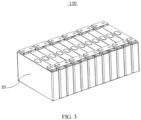
- FIG. 3 is a schematic structural diagram of a battery module 110 according to an embodiment of this application.
- the battery module 110 may include a plurality of battery cells 10.
- the plurality of battery cells 10 may first be connected in series, parallel, or series-parallel to form a battery module 110, and then a plurality of battery modules 110 are connected in series, parallel, or series-parallel to form a battery.
- the battery cell 10 may include a lithium-ion battery, a sodium-ion battery, a magnesium-ion battery, or the like. This is not limited in the embodiments of this application.
- the battery cell 10 may be cylindrical, flat, rectangular, or of other shapes, which is not limited in the embodiments of this application either.
- the battery cells 10 are typically categorized into three types depending on their packaging: cylindrical battery cell, prismatic battery cell, and pouch battery cell, which is not limited in the embodiments of this application either.
- the prismatic battery cell is used as an example for description.
- FIG. 4 is a schematic structural exploded view of a battery cell according to some embodiments of this application.
- the battery cell 10 is a smallest element constituting a battery.
- the battery cell 10 includes an end cover assembly 1, a housing 3, a cell assembly 2, and an adapting component 4, where the end cover assembly 1 includes an end cover 11 and an electrode terminal 12 disposed on the end cover.
- the end cover 11 is a component that covers an opening of the housing 3 to isolate an internal environment of the battery cell 10 from an external environment.
- Shape of the end cover 11 may be adapted to shape of the housing 3 to fit the housing 3.
- the end cover 11 may be made of a material with certain hardness and strength (for example, aluminum alloy), so that the end cover 11 is less likely to deform when subjected to extrusion and collision, allowing the battery cell 10 to have higher structural strength and enhanced safety performance.
- the housing 3 is an assembly configured to form the internal environment of the battery cell 10 together with the end cover 11, where the formed internal environment may be configured to accommodate the cell assembly 2, an electrolyte (not shown in the figure), and other components.
- the housing 3 and the end cover 11 may be separate components, an opening may be provided on the housing 3, and the end cover 11 covers the opening to form the internal environment of the battery cell 10.
- the housing 3 may be of various shapes and sizes, such as a rectangular shape, a cylindrical shape, and a hexagonal prism shape. Specifically, the shape of the housing 3 may be determined according to a specific shape and size of the cell assembly 2.
- the housing 3 may be made of various materials, such as copper, iron, aluminum, stainless steel, aluminum alloy, and plastic, which are not particularly limited in the embodiments of this application.
- the cell assembly 2 is a component in which electrochemical reactions take place in the battery cell 10.
- the housing 3 may include one or more cell assemblies 2.
- the cell assembly 2 is mainly formed by winding or stacking a positive electrode plate and a negative electrode plate, and a separator is generally provided between the positive electrode plate and the negative electrode plate. Portions of the positive electrode plate and the negative electrode plate that have active substances constitute a body portion of the cell assembly 2, while portions of the positive electrode plate and the negative electrode plate that have no active substances each constitute a tab (not shown in the figure).
- a positive tab and a negative tab may both be located at one end of the body portion or be located at two ends of the body portion respectively.
- the electrode terminal 12 is a component that is disposed on the end cover 11 and is configured to be electrically connected to the cell assembly 2 for outputting or inputting electrical energy of the battery cell.
- the electrode terminal 12 is electrically connected to the tab of the cell assembly 2 through the adapting component (not shown in the figure).
- the adapting component not shown in the figure.
- the adapting component is a conductive component, and the electrode terminal 12 is electrically connected through the adapting component.
- the adapting component is generally connected to the electrode terminal 12 by laser welding.
- Material of the adapting component includes but is not limited to nickel-plated copper or nickel strip. Due to the advantages such as good spot welding effect, low internal resistance, oxidation resistance, and corrosion resistance of nickel-plated copper or nickel strip, an adapting component made of nickel-plated copper or nickel strip allows the battery pack to have longer discharge time and better discharge effect.
- this application proposes an end cover assembly 1 applied to a battery cell 10.
- the end cover assembly 1 includes an end cover 11 and an electrode terminal 12.
- the end cover 11 is provided with a lead-out hole 113.
- the electrode terminal 12 is mounted on the end cover 11, a portion of the electrode terminal 12 passes through the lead-out hole 113, and a bottom surface 125 of the electrode terminal 12 extends out of the lead-out hole 113 and is used to be fixed to an adapting component 4 of the battery cell 10 by welding.
- the bottom surface 125 of the electrode terminal 12 refers to a surface of the electrode terminal 12 away from the outside of the end cover. After the end cover assembly 1 is mounted on the housing 3 of the battery cell 10, the electrode terminal 12 is located inside the battery cell 10 and faces a side surface of the cell assembly. In addition, the bottom surface 125 of the electrode terminal 12 is also used to be fixed to the adapting component 4 by welding.
- the lead-out hole 113 refers to a hole-like structure opened on the end cover 11, and two opposite sides of the end cover 11 can communicate with each other through the hole-like structure.
- Shape of the lead-out hole 113 may be circular, rectangular, triangular, rhombic, or the like.
- shape of the body of the electrode terminal 12 located in the lead-out hole 113 is consistent with the shape of the lead-out hole 113, so as to facilitate insertion and removal of the electrode terminal 12 in the lead-out hole 113.
- a portion of the electrode terminal 12 passing through the lead-out hole 113 means that the electrode terminal 12 passes through the lead-out hole 113, and a portion of the body of the electrode terminal 12 is located inside the lead-out hole 113 and a portion of the body of the electrode terminal 12 is located outside the lead-out hole 113.
- the adapting component 4 Being fixed by welding means that the adapting component 4 is connected and fixed to the electrode terminal 12 by welding.
- the adapting component 4 is provided with a protrusion at a position corresponding to the lead-out hole 113.
- the protrusion enters the lead-out hole 113 and abuts against the electrode terminal 12.
- metal shavings are generated. Due to a small size of a profiling structure, the removal effect cannot be guaranteed during removal of the metal shavings, and the metal shavings are highly prone to remaining. After the residual metal shavings enter the housing 3 of the battery cell 10, the metal shavings pierce the separator of the cell assembly, leading to short circuit of the cell assembly.
- the adapting component 4 that facilitates removal of the metal shavings can be used when the electrode terminal 12 is fixed to the adapting component 4 by welding, reducing the residual metal shavings after welding, thereby reducing the safety risks caused by the residual metal shavings.
- the adapting component 4 does not need to extend into the lead-out hole 113. After the electrode terminal 12 is fixed to the adapting component 4 by welding, the adapting component 4 does not enter the lead-out hole 113 during removal of the metal shavings after welding. As compared with the existing adapting component 4 with a profiling structure, the removal effect is better, preventing the metal shavings from remaining inside the profiling structure, thereby improving the removal effect on the metal shavings.
- a lower surface 114 of the end cover 11 has a first region 1141 opposite the adapting component 4, the adapting component 4 and the first region 1141 being spaced apart.
- the lower surface 114 of the end cover 11 refers to a side surface of the end cover 11. After the end cover assembly 1 is mounted on the housing 3 of the battery cell 10, the lower surface 114 faces the inside of the battery cell 10.
- the first region 1141 is formed on the lower surface 114 of the end cover 11, and may be a portion of the lower surface 114 or the entire lower surface 114.
- the lead-out hole 113 is formed in the first region 1141.
- the bottom surface 125 of the electrode terminal 12 protrudes from the lead-out hole 113.
- the bottom surface 125 of the electrode terminal 12 also protrudes from the first region 1141.
- the first region 1141 and the adapting component 4 being spaced apart allows for sufficient space between the adapting component 4 and the end cover 11 to accommodate the protruding portion of the electrode terminal 12.
- the adapting component 4 and the first region 1141 of the end cover being spaced apart can avoid interference between the adapting component 4 and the end cover 11, improving stability of welding between the adapting component 4 and the electrode terminal 12.
- a distance between the adapting component 4 and the first region 1141 is L, where 0 mm ⁇ L ⁇ 0.3 mm.
- the adapting component 4 and the lower surface 114 can be spaced apart, so as to reduce transfer of welding heat to the end cover 11, reducing adverse effects of the welding heat on the end cover 11.
- the value of the distance between the adapting component 4 and the lower surface 114 may be any one among 0.05 mm, 0.1 mm, 0.15 mm, 0.2 mm, 0.25 mm, ..., and 0.3 mm.
- the distance between the adapting component 4 and the first region 1141 is L, where L refers to the shortest distance between the adapting component 4 and the region.
- L refers to the shortest distance between the adapting component 4 and the region.
- the distance between them is L.
- the distance between the flat structure and the inclined structure at their closest positions is L.
- an extension height of the bottom surface 125 is T, where T ⁇ [0.05 mm, 1 mm].
- the extension height of the bottom surface 125 refers to a distance between the bottom surface 125 of the electrode terminal 12 and the opening of the lead-out hole 113 in the axial direction of the lead-out hole 113 in the case of the bottom surface 125 of the electrode terminal 12 protruding outside the lead-out hole 113.
- the extension height of the bottom surface 125 is T, where T is the shortest distance between the bottom surface 125 and the opening of the lead-out hole 113.
- T is the shortest distance between the bottom surface 125 and the opening of the lead-out hole 113.
- the value of the extension height of the bottom surface 125 of the electrode terminal 12 relative to the lead-out hole 113 is set in the range of [0.05 mm, 1 mm]. In the process of fixing the electrode terminal 12 to the adapting component 4 by welding, this reduces adverse effects of heat generated during fixing by welding on the end cover 11 while facilitating removal of the metal shavings, and also reduces the space occupied by the electrode terminal 12.
- the extension height of the bottom surface 125 of the electrode terminal 12 is larger, the bottom surface 125 of the electrode terminal 12 is farther away from the opening of the lead-out hole 113 of the end cover 11, resulting in better blocking effect on the welding heat but larger internal space occupied in the battery cell 10 in this case.
- the extension height of the bottom surface 125 of the electrode terminal 12 is smaller, the bottom surface 125 of the electrode terminal 12 is closer to the opening of the lead-out hole 113, resulting in worse blocking effect on the welding heat but smaller internal space occupied in the battery cell 10 in this case.
- the value of the extension height of the bottom surface 125 of the electrode terminal 12 relative to the lead-out hole 113 being set in the range of [0.05 mm, 1 mm] effectively reduces the internal space occupied in the battery cell 10 while effectively preventing transfer of the welding heat.
- the protrusion height of the bottom surface 125 of the electrode terminal 12 is less than 0.05 mm, in the process of fixing the electrode terminal 12 to the adapting component 4 by welding, the welding heat is transferred to the end cover 11, causing the undesirable situations such as deformation of the end cover 11 due to heating.
- the protrusion height of the bottom surface 125 of the electrode terminal 12 is greater than 1 mm, the electrode terminal 12 has an excessive extension length to the inside of the battery cell 10, and thus occupies the internal space of the battery cell 10, which is not conducive to the layout of the internal structure of the battery cell 10.
- the value of the protrusion height of the bottom surface 125 of the electrode terminal 12 may be any one of 0.05 mm, 0.10 mm, 0.15 mm, 0.20 mm, 0.25 mm, 0.30 mm, 0.35 mm, 0.40 mm, 0.45 mm, 0.50 mm, 0.55 mm, 0.60 mm, 0.65 mm, 0.70 mm, 0.75 mm, 0.80 mm, 0.85 mm, 0.90 mm, 0.95 mm, ..., and 1.00 mm.
- the protrusion height T of the bottom surface 125 of the electrode terminal 12 is 0.2 mm or 0.3 mm.
- the protrusion height of the bottom surface 125 of the electrode terminal 12 is 0.2 mm.
- the value of the protrusion height of the bottom surface 125 of the electrode terminal 12 being set to 0.2 mm effectively reduces the protrusion height of the electrode terminal 12 while ensuring that the welding heat between the electrode terminal 12 and the adapting component 4 is not transferred to the end cover 11, reducing adverse effects on the internal space of the battery cell 10.
- the protrusion height of the bottom surface 125 of the electrode terminal 12 is 0.3 mm.
- the protrusion height of the bottom surface 125 of the electrode terminal 12 being set to 0.3 mm allows the bottom surface 125 of the electrode terminal 12 to be farther away from the end cover 11 while ensuring that the electrode terminal 12 has little effect on the internal space of the battery cell 10, reducing transfer of the welding heat between the electrode terminal 12 and the adapting component 4 to the end cover 11.
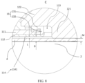
- the electrode terminal 12 includes a terminal plate 122 and an extension portion 121, where the terminal plate 122 is located at a side of the end cover 11 and covers the lead-out hole 113, the end cover assembly 1 further includes a sealing ring 13, at least a portion of the sealing ring 13 is located between the terminal plate 122 and the end cover 11 to seal the lead-out hole 113, the extension portion 121 extends into the lead-out hole 113, and in a radial direction of the lead-out hole 113, as shown in FIG. 7 , a distance between the extension portion 121 and the sealing ring 13 is k, where k ⁇ [1.5 mm, 2.5 mm].
- the electrode terminal 12 has the terminal plate 122 and the extension portion 121 that are connected, where the extension portion 121 passes through the lead-out hole 113 of the end cover 11, the terminal plate 122 is located outside the lead-out hole 113 and covers the lead-out hole 113, the bottom surface 125 of the electrode terminal 12 is formed on the extension portion 121, an end of the extension portion 121 having the bottom surface 125 extends out of the lead-out hole 113, the sealing ring 13 fits radially outward the extension portion 121, and a portion of the sealing ring 13 seals the terminal plate 122 and the end cover 11.
- the provision of the sealing ring 13 achieves the sealing of the lead-out hole 113, effectively realizing internal and external isolation of the battery cell 10.
- the extension portion 121 and the sealing ring 13 being spaced apart reduces transfer of the welding heat to the sealing ring 13 and reduces the adverse effects of the welding heat on the sealing ring 13, guaranteeing the sealing effect of the sealing ring 13.
- the value of the distance between the extension portion 121 and the sealing ring 13 being set in the range of [1.5 mm, 2.5 mm] allows for a desirable gap between the sealing ring 13 and the extension portion 121, preventing transfer of heat to the sealing ring 13 in the process of fixing the electrode terminal 12 to the adapting component 4 by welding. Based on this, the structure is more compact, preventing the structure from occupying the space of the battery cell 10.
- the gap between the sealing ring 13 and the extension portion 121 is small, and the small gap is prone to causing transfer of the welding heat to the sealing ring 13 during welding of the electrode terminal 12 and the adapting component 4, which easily leads to damage to the sealing ring 13 and inconvenient mounting of the sealing ring 13.
- the gap between the extension portion 121 and the sealing ring 13 is greater than 2.5 mm, the gap between the sealing ring 13 and the extension portion 121 is large, and the large gap causes displacement in the radial direction of the sealing ring 13, which is prone to resulting in lower mounting accuracy.
- the value of the distance between the extension portion 121 and the sealing ring 13 may be any one of 1.5 mm, 1.6 mm, 1.7 mm, 1.8 mm, 1.9 mm, 2.0 mm, 2.1 mm, 2.2 mm, 2.3 mm, 2.4 mm, ..., and 2.5 mm.
- the distance k between the extension portion 121 and the sealing ring 13 is 1.6 mm or 2 mm.
- the distance between the extension portion 121 and the sealing ring 13 is 1.6 mm.
- the value of the distance between the extension portion 121 and the sealing ring 13 being set to 1.6 mm ensures effective mounting of the sealing ring 13 and the extension portion 121, blocks the welding heat, and also allows the structure to be more compact, reducing the space occupied on the battery cell 10.
- the distance between the extension portion 121 and the sealing ring 13 is 2 mm.
- the value of the distance between the extension portion 121 and the sealing ring 13 being set to 2 mm appropriately increases the value of the preset gap, and can increase the distance between the extension portion 121 and the sealing ring 13, which further improves the blocking effect on the welding heat and also facilitates the positioning operation during assembly.
- the sealing ring 13 includes a first portion 131 and a second portion 132, where the first portion 131 is located between the terminal plate 122 and the end cover 11, the second portion 132 extends into the lead-out hole 113, and in the radial direction of the lead-out hole 113, a distance between the extension portion 121 and the second portion 132 is k, where k ⁇ [1.5 mm, 2.5 mm].
- the sealing ring 13 fits outside the extension portion 121.
- the first portion 131 of the sealing ring 13 is compressed between the terminal plate 122 and the end cover 11, and the second portion 132 of the sealing ring 13 is provided in the lead-out hole 113 and is fitted to a hole wall of the lead-out hole 113 (spaced apart from the extension portion 121).
- the sealing ring 13 being provided as the first portion 131 and the second portion 132 can improve the positioning effect of the sealing ring 13, thereby improving the sealing effect of the sealing ring 13.
- the value of the distance between the extension portion 121 and the second portion 132 being set in the range of [1.5 mm, 2.5 mm] allows for a desirable gap between the second portion 132 and the extension portion 121, preventing transfer of heat to the sealing ring 13 in the process of fixing the electrode terminal 12 to the adapting component 4 by welding. Based on this, the mounting accuracy can also be effectively improved.
- the extension portion 121 is a cylindrical structure
- the sealing ring 13 is an annular member, where a diameter of the cylindrical structure is d1, and an inner diameter of the annular member is d2, where d1/d2 ⁇ [0.75, 2.5].
- the extension portion 121 being set as the cylindrical structure and the sealing ring 13 being set as the annular member facilitate coaxial assembly of the sealing ring 13 and the extension portion 121 during mounting, improving the assembly accuracy of the sealing ring 13.
- a ratio of the diameter of the cylindrical structure to the inner diameter of the annular member being set in the range of [0.75, 2.5] allows for a sufficiently large cross section of the extension portion 121, so that the extension portion 121 has a large current flow area after connected to the adapting component 4, reducing the situation that the performance of the battery cell 10 is affected by heating at the connection position.
- extension portion 121 being set as the cylindrical structure and the sealing ring 13 being set as the annular member facilitate their processing during manufacturing, improving the processing efficiency.
- a sleeve is needed as an auxiliary tool for mounting.
- the sealing ring 13 fits around the sleeve, and the extension portion 121 is inserted into the sleeve, such that the sealing ring 13 and the extension portion 121 can be coaxially arranged quickly using the sleeve, so as to achieve positioning and mounting of the sealing ring 13 and the electrode terminal 12, thereby improving the mounting accuracy.
- d1/d2 may be any one of 0.75, 1, 1.25, 1.5, 1.75, 2.0, 2.25, ..., and 2.5.
- the diameter d1 of the cylindrical structure is ⁇ [12 mm, 16 mm]
- the inner diameter d2 of the annular member is ⁇ [15.2 mm, 20 mm].
- the diameter of the cylindrical structure and the inner diameter of the annular member being set to the foregoing values further improves the mounting accuracy of the sealing ring 13, and allows for a large cross-sectional area of the extension portion 121 of the cylindrical structure, further increasing the current flow area between the extension portion 121 and the adapting component 4.
- the value of d1 may be any one of 12 mm, 13 mm, 14 mm, 15 mm, ..., and 16 mm.
- the value of d1 may be any one of 15.2 mm, 15.5 mm, 16 mm, 16.5 mm, ..., and 20 mm.
- the diameter d1 of the cylindrical structure is 12 mm
- the diameter d1 of the cylindrical structure is 12 mm
- this allows for a large cross-sectional area of the extension portion 121 of the cylindrical structure, increasing the current flow area between the extension portion 121 and the adapting component 4, thereby reducing the undesirable situations such as de-welding due to excessive heat during use.
- the diameter d1 of the cylindrical structure is set to 16 mm
- this allows for a larger cross-sectional area of the extension portion 121 of the cylindrical structure, further increasing the current flow area between the extension portion 121 and the adapting component 4, thereby further reducing the undesirable situations such as de-welding due to excessive heat during use.
- the electrode terminal 12 further includes an insulating member 123 and a fixing member 124, where the insulating member 123 is disposed on a circumference of the terminal plate 122; and the fixing member 124 is separated from the electrode terminal 12 through the insulating member 123, the fixing member 124 is connected to the insulating member 123 and the end cover 11, and the fixing member 124 is a conductive member.
- the terminal plate 122, the insulating member 123, the fixing member 124, and the end cover 11 are connected in sequence to connect and fix the electrode terminal 12 to the end cover 11.
- the insulating member 123 is used to insulate the electrode terminal 12 from the end cover 11, improving safety in use.
- the fixing member 124 is a welding ring
- the insulating member 123 is plastic.
- the electrode terminal 12, the welding ring, and the plastic can be assembled and then mounted onto the end cover 11. During assembly, the welding ring is pressed onto the electrode terminal 12, and the plastic is injected into a gap between the welding ring and the electrode terminal 12 by injection molding, thereby achieving connection and fixation of the welding ring and the electrode terminal 12.
- the bottom surface 125 is flat.
- the bottom surface 125 of the electrode terminal 12 is connected and fixed to the adapting component 4 of the battery cell 10 by welding.
- the bottom surface 125 of the electrode terminal 12 extends out of the lead-out hole 113, so as to use the adapting component 4 of a flat structure.
- the electrode terminal 12 is fixed to the adapting component 4 by welding, the bottom surface 125 of the electrode terminal 12 abuts against a large surface of the adapting component 4, and the electrode terminal 12 and the adapting component 4 are connected and fixed by welding.
- the bottom surface 125 of the electrode terminal 12 being set to be flat increases a contact area between the electrode terminal 12 and the adapting component 4 that are connected, improves connection strength between the electrode terminal 12 and the adapting component 4, and also increases the current flow area between the electrode terminal 12 and the adapting component 4, thereby reducing the situation that the performance of the battery cell 10 is affected by heating at the connection position.
- the bottom surface 125 may be inclined or curved, and the bottom surface 125 is also provided with a recess.
- the end cover 11 is an integral structure, the end cover 11 itself is the insulating member 123, and the lead-out hole 113 is opened on the end cover 11.
- the end cover 11 is a separate structure, including a top cover plate 111 and an insulating plate 112.
- the top cover plate 111 is connected and fixed to the insulating plate 112 by adhering, fasteners, riveting, welding, or the like.
- the end cover 11 is mounted on the housing 3 of the battery cell 10
- the top cover plate 111 faces away from the inside of the housing 3, and the insulating plate 112 faces the inside of the housing 3.
- a first hole portion 1131 is opened on the top cover plate 111 and a second hole portion 1132 is opened on the insulating plate 112. After the top cover plate 111 is connected to the insulating plate 112, the first hole portion 1131 and the second hole portion 1132 overlap to form the lead-out hole 113.
- first hole portion 1131 and the second hole portion 1132 may be coaxially provided.
- the first hole portion 1131 and the second hole portion 1132 being coaxially provided makes the structure of the lead-out hole 113 more convenient for the assembly of the electrode terminal 12.
- an opening of the first hole portion 1131 has a first flanging protruding toward the insulating plate 112, and an opening of the second hole portion 1132 has a second flanging protruding toward the top cover plate 111.
- size of the first flanging is larger than size of the second flanging.
- the first flanging abuts radially outward against the second flanging, and an end of the second portion 132 of the sealing ring 13 close to the inside of the housing 3 abuts against the insulating plate 112 and is located between the first flanging and the second flanging, such that the top cover plate 111 and the insulating plate 112 are effectively sealed using the second portion 132.
- a second aspect of this application proposes a battery cell 10 including the end cover assembly 1 and adapting component 4 as described above, where the adapting component 4 covers the bottom surface 125 of the electrode terminal 12 and is fixed to the bottom surface 125 by welding.
- the adapting component 4 is a flat plate structure, which can facilitate removal of the metal shavings and manufacturing.
- a side of the adapting component 4 facing the electrode terminal 12 is provided with a recess, a portion of the electrode terminal 12 is accommodated in the recess, and the adapting component 4 is flat at a side back away from the electrode terminal or is provided with a protrusion at a position corresponding to the recess. This facilitates removal of the metal shavings. This can also improve compactness of the internal structure of the battery cell 10.
- the battery cell 10 further includes a cell assembly 2, where the cell assembly 2 includes a body portion 22 and a tab 21, and the adapting component 4 connects the tab 21 and the electrode terminal 12.
- thickness of a portion at which the adapting component 4 is welded to the electrode terminal 12 is M.
- a lower surface 114 of the end cover 11 has a first region 1141 opposite the adapting component 4, where a distance from the first region 1141 to the cell assembly 2 is D, and an extension height of the bottom surface 125 is T, where T ⁇ (D - M).
- T T ⁇ (D - M).
- the extension height of the bottom surface 125 of the electrode terminal 12 is T, where T ⁇ [0.05 mm, 1 mm].
- the value of the extension height of the bottom surface 125 of the electrode terminal 12 relative to the lead-out hole 113 is set in the range of [0.05 mm, 1 mm]. In the process of fixing the electrode terminal 12 to the adapting component 4 by welding, this reduces adverse effects of heat generated during fixing by welding on the end cover while facilitating removal of the metal shavings, and also reduces the space occupied by the electrode terminal 12.
- a third aspect of this application proposes a battery, including the battery cell 10 as described above.
- a fourth aspect of this application proposes an electric apparatus, where the electric apparatus includes the battery cell 10 as described above.
- this application proposes an end cover assembly 1, and the end cover assembly 1 includes an end cover 11, a sealing ring 13, and an electrode terminal 12.
- the end cover 11 includes a top cover plate 111 and an insulating plate 112, and the end cover 11 formed by the top cover plate 111 and the insulating plate 112 is provided with a lead-out hole 113.
- the electrode terminal 12 includes a terminal plate 122, an extension portion 121, an insulating member 123 (for example, plastic), and a fixing member 124 (for example, a welding ring).
- the sealing ring 13 includes a first portion 131 and a second portion 132.
- the fixing member 124 fits radially outward the terminal plate 122, and the insulating member 123 is filled between the terminal plate 122 and the fixing member 124.
- the sealing ring 13 fits with the top cover plate 111, such that the first portion 131 of the sealing ring 13 abuts against the top cover plate 111, and the second portion 132 of the sealing ring 13 is inserted into the lead-out hole 113 and is fitted to an inner wall of the lead-out hole 113; and the extension portion 121 of the electrode terminal 12 is inserted into the sealing ring 13, such that the terminal plate 122 abuts against the first portion 131 of the sealing ring 13, where a distance between the extension portion 121 and the second portion 132 of the sealing ring 13 is k, where k ⁇ [1.5 mm, 2.5 mm].
- the fixing member 124 is connected and fixed to the top cover plate 111.
- the insulating member 123 is connected and fixed to the top cover plate 111.
- the bottom surface 125 of the assembled electrode terminal 12 extends out of the lead-out hole 113, and the extension height is T, where T ⁇ [0.05 mm, 1 mm].
- the extension portion 121 is a cylindrical structure
- the second portion 132 of the sealing ring 13 is an annular member, where a diameter of the cylindrical structure is d1, and an inner diameter of the annular member is d2, where d1/d2 ⁇ [0.75, 2.5].
- the adapting component 4 that facilitates removal of the metal shavings can be used when the electrode terminal 12 is fixed to the adapting component 4 by welding, reducing the residual metal shavings after welding, thereby reducing the safety risks caused by the residual metal shavings.
Landscapes
- Chemical & Material Sciences (AREA)
- Chemical Kinetics & Catalysis (AREA)
- Electrochemistry (AREA)
- General Chemical & Material Sciences (AREA)
- Engineering & Computer Science (AREA)
- Manufacturing & Machinery (AREA)
- Materials Engineering (AREA)
- Sealing Battery Cases Or Jackets (AREA)
- Connection Of Batteries Or Terminals (AREA)
- Battery Mounting, Suspending (AREA)
Applications Claiming Priority (2)
| Application Number | Priority Date | Filing Date | Title |
|---|---|---|---|
| CN202222268176.8U CN218827483U (zh) | 2022-08-26 | 2022-08-26 | 端盖组件、电池单体、电池及用电装置 |
| PCT/CN2022/143266 WO2024040837A1 (zh) | 2022-08-26 | 2022-12-29 | 端盖组件、电池单体、电池及用电装置 |
Publications (2)
| Publication Number | Publication Date |
|---|---|
| EP4503221A1 true EP4503221A1 (de) | 2025-02-05 |
| EP4503221A4 EP4503221A4 (de) | 2025-10-08 |
Family
ID=87252148
Family Applications (1)
| Application Number | Title | Priority Date | Filing Date |
|---|---|---|---|
| EP22956368.9A Pending EP4503221A4 (de) | 2022-08-26 | 2022-12-29 | Endkappenanordnung, batteriezelle, batterie und elektrische vorrichtung |
Country Status (4)
| Country | Link |
|---|---|
| US (1) | US20250062457A1 (de) |
| EP (1) | EP4503221A4 (de) |
| CN (1) | CN218827483U (de) |
| WO (1) | WO2024040837A1 (de) |
Family Cites Families (8)
| Publication number | Priority date | Publication date | Assignee | Title |
|---|---|---|---|---|
| KR102663722B1 (ko) * | 2016-09-05 | 2024-05-07 | 삼성에스디아이 주식회사 | 이차 전지 |
| CN211045490U (zh) * | 2019-12-30 | 2020-07-17 | 宁德时代新能源科技股份有限公司 | 二次电池及用于其的顶盖组件、电池模块和装置 |
| CN112072058B (zh) * | 2020-11-11 | 2021-04-06 | 江苏时代新能源科技有限公司 | 电池单体、电池、用电设备及电池制造方法 |
| CN215988974U (zh) * | 2021-08-23 | 2022-03-08 | 宁德时代新能源科技股份有限公司 | 电池单体、电池以及用电装置 |
| CN216120653U (zh) * | 2021-10-20 | 2022-03-22 | 宁德时代新能源科技股份有限公司 | 电池单体、电池及用电设备 |
| CN216120664U (zh) * | 2021-10-20 | 2022-03-22 | 宁德时代新能源科技股份有限公司 | 电池单体、电池及用电装置 |
| CN216903143U (zh) * | 2022-01-28 | 2022-07-05 | 宁德时代新能源科技股份有限公司 | 电池单体、电池及用电装置 |
| CN115000641B (zh) * | 2022-08-04 | 2022-11-29 | 江苏时代新能源科技有限公司 | 端盖组件、电池单体、电池以及用电装置 |
-
2022
- 2022-08-26 CN CN202222268176.8U patent/CN218827483U/zh active Active
- 2022-12-29 WO PCT/CN2022/143266 patent/WO2024040837A1/zh not_active Ceased
- 2022-12-29 EP EP22956368.9A patent/EP4503221A4/de active Pending
-
2024
- 2024-11-07 US US18/940,586 patent/US20250062457A1/en active Pending
Also Published As
| Publication number | Publication date |
|---|---|
| WO2024040837A1 (zh) | 2024-02-29 |
| CN218827483U (zh) | 2023-04-07 |
| US20250062457A1 (en) | 2025-02-20 |
| EP4503221A4 (de) | 2025-10-08 |
Similar Documents
| Publication | Publication Date | Title |
|---|---|---|
| US20240304918A1 (en) | Box of battery, battery, electrical apparatus, and manufacturing device for batteries | |
| EP4391205A1 (de) | Elektrodenfolie, elektrodenanordnung, batteriezelle, batterie und elektrische vorrichtung | |
| CN217306722U (zh) | 端盖组件、电池单体、电池及用电装置 | |
| US20240363980A1 (en) | Battery cell and manufacturing method thereof, battery, and electric apparatus | |
| US20240380039A1 (en) | Battery top cover, top cover assembly, battery cell, battery, and power consuming device | |
| EP4401225A1 (de) | Batteriegehäuse, batteriezelle, batterie und elektrische vorrichtung | |
| US20230261334A1 (en) | Battery cell, battery, electric device, and manufacturing method and device of battery cell | |
| US20240413507A1 (en) | Battery cell top cover, battery cell, battery, electric device, and electrolyte injection nozzle | |
| US20240313309A1 (en) | Battery top cover assembly, battery cell, battery, and electric apparatus | |
| US20230238642A1 (en) | Battery cell, battery, power consuming device, and method for manufacturing battery cell | |
| US12469926B2 (en) | Battery cell, cover assembly, battery, electric apparatus, method, and device | |
| US20260074375A1 (en) | Battery cell, battery, and power consuming apparatus | |
| US20250015405A1 (en) | Battery cell, battery, and electric device | |
| US20240363975A1 (en) | Connecting component, battery cell, battery, and electric apparatus | |
| CN119627373B (zh) | 电池单体的制造方法、电池单体、电池及用电装置 | |
| EP4503221A1 (de) | Endkappenanordnung, batteriezelle, batterie und elektrische vorrichtung | |
| CN219203426U (zh) | 电池及用电设备 | |
| US20230207983A1 (en) | Battery cell, battery, electric apparatus, and manufacturing method and device of battery cell | |
| EP4672461A1 (de) | Träger, batteriezelle, batterie und elektrische vorrichtung | |
| EP4672459A1 (de) | Batteriezelle, batterie, elektrische vorrichtung und träger | |
| EP4664669A1 (de) | Batteriezelle, batterie und elektrische vorrichtung | |
| EP4428998A1 (de) | Batteriezelle, batterie und elektrische vorrichtung | |
| US12132230B2 (en) | Battery cell, battery, power consumption device, and method and device for manufacturing battery cell | |
| CN216850117U (zh) | 电池的箱体、电池及用电装置 | |
| EP4712236A1 (de) | Batteriezelle, batterie und elektrische vorrichtung |
Legal Events
| Date | Code | Title | Description |
|---|---|---|---|
| STAA | Information on the status of an ep patent application or granted ep patent |
Free format text: STATUS: THE INTERNATIONAL PUBLICATION HAS BEEN MADE |
|
| PUAI | Public reference made under article 153(3) epc to a published international application that has entered the european phase |
Free format text: ORIGINAL CODE: 0009012 |
|
| STAA | Information on the status of an ep patent application or granted ep patent |
Free format text: STATUS: REQUEST FOR EXAMINATION WAS MADE |
|
| 17P | Request for examination filed |
Effective date: 20241025 |
|
| AK | Designated contracting states |
Kind code of ref document: A1 Designated state(s): AL AT BE BG CH CY CZ DE DK EE ES FI FR GB GR HR HU IE IS IT LI LT LU LV MC ME MK MT NL NO PL PT RO RS SE SI SK SM TR |
|
| A4 | Supplementary search report drawn up and despatched |
Effective date: 20250909 |
|
| RIC1 | Information provided on ipc code assigned before grant |
Ipc: H01M 10/0525 20100101AFI20250903BHEP Ipc: H01M 10/054 20100101ALI20250903BHEP Ipc: H01M 10/058 20100101ALI20250903BHEP Ipc: H01M 6/14 20060101ALI20250903BHEP Ipc: H01M 50/176 20210101ALI20250903BHEP Ipc: H01M 50/531 20210101ALI20250903BHEP Ipc: H01M 50/55 20210101ALI20250903BHEP |
|
| DAV | Request for validation of the european patent (deleted) | ||
| DAX | Request for extension of the european patent (deleted) |