EP4503255A1 - Dispositif de commande de batterie et procédé de commande de batterie - Google Patents
Dispositif de commande de batterie et procédé de commande de batterie Download PDFInfo
- Publication number
- EP4503255A1 EP4503255A1 EP23780996.7A EP23780996A EP4503255A1 EP 4503255 A1 EP4503255 A1 EP 4503255A1 EP 23780996 A EP23780996 A EP 23780996A EP 4503255 A1 EP4503255 A1 EP 4503255A1
- Authority
- EP
- European Patent Office
- Prior art keywords
- voltage
- correction factor
- battery
- secondary battery
- calculation unit
- Prior art date
- Legal status (The legal status is an assumption and is not a legal conclusion. Google has not performed a legal analysis and makes no representation as to the accuracy of the status listed.)
- Pending
Links
Images






Classifications
-
- B—PERFORMING OPERATIONS; TRANSPORTING
- B60—VEHICLES IN GENERAL
- B60L—PROPULSION OF ELECTRICALLY-PROPELLED VEHICLES; SUPPLYING ELECTRIC POWER FOR AUXILIARY EQUIPMENT OF ELECTRICALLY-PROPELLED VEHICLES; ELECTRODYNAMIC BRAKE SYSTEMS FOR VEHICLES IN GENERAL; MAGNETIC SUSPENSION OR LEVITATION FOR VEHICLES; MONITORING OPERATING VARIABLES OF ELECTRICALLY-PROPELLED VEHICLES; ELECTRIC SAFETY DEVICES FOR ELECTRICALLY-PROPELLED VEHICLES
- B60L3/00—Electric devices on electrically-propelled vehicles for safety purposes; Monitoring operating variables, e.g. speed, deceleration or energy consumption
- B60L3/12—Recording operating variables ; Monitoring of operating variables
-
- B—PERFORMING OPERATIONS; TRANSPORTING
- B60—VEHICLES IN GENERAL
- B60L—PROPULSION OF ELECTRICALLY-PROPELLED VEHICLES; SUPPLYING ELECTRIC POWER FOR AUXILIARY EQUIPMENT OF ELECTRICALLY-PROPELLED VEHICLES; ELECTRODYNAMIC BRAKE SYSTEMS FOR VEHICLES IN GENERAL; MAGNETIC SUSPENSION OR LEVITATION FOR VEHICLES; MONITORING OPERATING VARIABLES OF ELECTRICALLY-PROPELLED VEHICLES; ELECTRIC SAFETY DEVICES FOR ELECTRICALLY-PROPELLED VEHICLES
- B60L58/00—Methods or circuit arrangements for monitoring or controlling batteries or fuel cells, specially adapted for electric vehicles
- B60L58/10—Methods or circuit arrangements for monitoring or controlling batteries or fuel cells, specially adapted for electric vehicles for monitoring or controlling batteries
- B60L58/12—Methods or circuit arrangements for monitoring or controlling batteries or fuel cells, specially adapted for electric vehicles for monitoring or controlling batteries responding to state of charge [SoC]
-
- B—PERFORMING OPERATIONS; TRANSPORTING
- B60—VEHICLES IN GENERAL
- B60L—PROPULSION OF ELECTRICALLY-PROPELLED VEHICLES; SUPPLYING ELECTRIC POWER FOR AUXILIARY EQUIPMENT OF ELECTRICALLY-PROPELLED VEHICLES; ELECTRODYNAMIC BRAKE SYSTEMS FOR VEHICLES IN GENERAL; MAGNETIC SUSPENSION OR LEVITATION FOR VEHICLES; MONITORING OPERATING VARIABLES OF ELECTRICALLY-PROPELLED VEHICLES; ELECTRIC SAFETY DEVICES FOR ELECTRICALLY-PROPELLED VEHICLES
- B60L58/00—Methods or circuit arrangements for monitoring or controlling batteries or fuel cells, specially adapted for electric vehicles
- B60L58/10—Methods or circuit arrangements for monitoring or controlling batteries or fuel cells, specially adapted for electric vehicles for monitoring or controlling batteries
- B60L58/12—Methods or circuit arrangements for monitoring or controlling batteries or fuel cells, specially adapted for electric vehicles for monitoring or controlling batteries responding to state of charge [SoC]
- B60L58/13—Maintaining the SoC within a determined range
-
- B—PERFORMING OPERATIONS; TRANSPORTING
- B60—VEHICLES IN GENERAL
- B60L—PROPULSION OF ELECTRICALLY-PROPELLED VEHICLES; SUPPLYING ELECTRIC POWER FOR AUXILIARY EQUIPMENT OF ELECTRICALLY-PROPELLED VEHICLES; ELECTRODYNAMIC BRAKE SYSTEMS FOR VEHICLES IN GENERAL; MAGNETIC SUSPENSION OR LEVITATION FOR VEHICLES; MONITORING OPERATING VARIABLES OF ELECTRICALLY-PROPELLED VEHICLES; ELECTRIC SAFETY DEVICES FOR ELECTRICALLY-PROPELLED VEHICLES
- B60L58/00—Methods or circuit arrangements for monitoring or controlling batteries or fuel cells, specially adapted for electric vehicles
- B60L58/10—Methods or circuit arrangements for monitoring or controlling batteries or fuel cells, specially adapted for electric vehicles for monitoring or controlling batteries
- B60L58/12—Methods or circuit arrangements for monitoring or controlling batteries or fuel cells, specially adapted for electric vehicles for monitoring or controlling batteries responding to state of charge [SoC]
- B60L58/14—Preventing excessive discharging
-
- B—PERFORMING OPERATIONS; TRANSPORTING
- B60—VEHICLES IN GENERAL
- B60L—PROPULSION OF ELECTRICALLY-PROPELLED VEHICLES; SUPPLYING ELECTRIC POWER FOR AUXILIARY EQUIPMENT OF ELECTRICALLY-PROPELLED VEHICLES; ELECTRODYNAMIC BRAKE SYSTEMS FOR VEHICLES IN GENERAL; MAGNETIC SUSPENSION OR LEVITATION FOR VEHICLES; MONITORING OPERATING VARIABLES OF ELECTRICALLY-PROPELLED VEHICLES; ELECTRIC SAFETY DEVICES FOR ELECTRICALLY-PROPELLED VEHICLES
- B60L58/00—Methods or circuit arrangements for monitoring or controlling batteries or fuel cells, specially adapted for electric vehicles
- B60L58/10—Methods or circuit arrangements for monitoring or controlling batteries or fuel cells, specially adapted for electric vehicles for monitoring or controlling batteries
- B60L58/16—Methods or circuit arrangements for monitoring or controlling batteries or fuel cells, specially adapted for electric vehicles for monitoring or controlling batteries responding to battery ageing, e.g. to the number of charging cycles or the state of health [SoH]
-
- G—PHYSICS
- G01—MEASURING; TESTING
- G01R—MEASURING ELECTRIC VARIABLES; MEASURING MAGNETIC VARIABLES
- G01R31/00—Arrangements for testing electric properties; Arrangements for locating electric faults; Arrangements for electrical testing characterised by what is being tested not provided for elsewhere
- G01R31/36—Arrangements for testing, measuring or monitoring the electrical condition of accumulators or electric batteries, e.g. capacity or state of charge [SoC]
-
- G—PHYSICS
- G01—MEASURING; TESTING
- G01R—MEASURING ELECTRIC VARIABLES; MEASURING MAGNETIC VARIABLES
- G01R31/00—Arrangements for testing electric properties; Arrangements for locating electric faults; Arrangements for electrical testing characterised by what is being tested not provided for elsewhere
- G01R31/36—Arrangements for testing, measuring or monitoring the electrical condition of accumulators or electric batteries, e.g. capacity or state of charge [SoC]
- G01R31/367—Software therefor, e.g. for battery testing using modelling or look-up tables
-
- G—PHYSICS
- G01—MEASURING; TESTING
- G01R—MEASURING ELECTRIC VARIABLES; MEASURING MAGNETIC VARIABLES
- G01R31/00—Arrangements for testing electric properties; Arrangements for locating electric faults; Arrangements for electrical testing characterised by what is being tested not provided for elsewhere
- G01R31/36—Arrangements for testing, measuring or monitoring the electrical condition of accumulators or electric batteries, e.g. capacity or state of charge [SoC]
- G01R31/382—Arrangements for monitoring battery or accumulator variables, e.g. SoC
-
- G—PHYSICS
- G01—MEASURING; TESTING
- G01R—MEASURING ELECTRIC VARIABLES; MEASURING MAGNETIC VARIABLES
- G01R31/00—Arrangements for testing electric properties; Arrangements for locating electric faults; Arrangements for electrical testing characterised by what is being tested not provided for elsewhere
- G01R31/36—Arrangements for testing, measuring or monitoring the electrical condition of accumulators or electric batteries, e.g. capacity or state of charge [SoC]
- G01R31/382—Arrangements for monitoring battery or accumulator variables, e.g. SoC
- G01R31/3842—Arrangements for monitoring battery or accumulator variables, e.g. SoC combining voltage and current measurements
-
- G—PHYSICS
- G01—MEASURING; TESTING
- G01R—MEASURING ELECTRIC VARIABLES; MEASURING MAGNETIC VARIABLES
- G01R31/00—Arrangements for testing electric properties; Arrangements for locating electric faults; Arrangements for electrical testing characterised by what is being tested not provided for elsewhere
- G01R31/36—Arrangements for testing, measuring or monitoring the electrical condition of accumulators or electric batteries, e.g. capacity or state of charge [SoC]
- G01R31/385—Arrangements for measuring battery or accumulator variables
-
- G—PHYSICS
- G01—MEASURING; TESTING
- G01R—MEASURING ELECTRIC VARIABLES; MEASURING MAGNETIC VARIABLES
- G01R31/00—Arrangements for testing electric properties; Arrangements for locating electric faults; Arrangements for electrical testing characterised by what is being tested not provided for elsewhere
- G01R31/36—Arrangements for testing, measuring or monitoring the electrical condition of accumulators or electric batteries, e.g. capacity or state of charge [SoC]
- G01R31/389—Measuring internal impedance, internal conductance or related variables
-
- G—PHYSICS
- G01—MEASURING; TESTING
- G01R—MEASURING ELECTRIC VARIABLES; MEASURING MAGNETIC VARIABLES
- G01R31/00—Arrangements for testing electric properties; Arrangements for locating electric faults; Arrangements for electrical testing characterised by what is being tested not provided for elsewhere
- G01R31/36—Arrangements for testing, measuring or monitoring the electrical condition of accumulators or electric batteries, e.g. capacity or state of charge [SoC]
- G01R31/392—Determining battery ageing or deterioration, e.g. state of health
-
- H—ELECTRICITY
- H01—ELECTRIC ELEMENTS
- H01M—PROCESSES OR MEANS, e.g. BATTERIES, FOR THE DIRECT CONVERSION OF CHEMICAL ENERGY INTO ELECTRICAL ENERGY
- H01M10/00—Secondary cells; Manufacture thereof
- H01M10/42—Methods or arrangements for servicing or maintenance of secondary cells or secondary half-cells
- H01M10/425—Structural combination with electronic components, e.g. electronic circuits integrated to the outside of the casing
-
- H—ELECTRICITY
- H01—ELECTRIC ELEMENTS
- H01M—PROCESSES OR MEANS, e.g. BATTERIES, FOR THE DIRECT CONVERSION OF CHEMICAL ENERGY INTO ELECTRICAL ENERGY
- H01M10/00—Secondary cells; Manufacture thereof
- H01M10/42—Methods or arrangements for servicing or maintenance of secondary cells or secondary half-cells
- H01M10/44—Methods for charging or discharging
-
- H—ELECTRICITY
- H01—ELECTRIC ELEMENTS
- H01M—PROCESSES OR MEANS, e.g. BATTERIES, FOR THE DIRECT CONVERSION OF CHEMICAL ENERGY INTO ELECTRICAL ENERGY
- H01M10/00—Secondary cells; Manufacture thereof
- H01M10/42—Methods or arrangements for servicing or maintenance of secondary cells or secondary half-cells
- H01M10/48—Accumulators combined with arrangements for measuring, testing or indicating the condition of cells, e.g. the level or density of the electrolyte
-
- H—ELECTRICITY
- H02—GENERATION; CONVERSION OR DISTRIBUTION OF ELECTRIC POWER
- H02J—ELECTRIC POWER NETWORKS; CIRCUIT ARRANGEMENTS OR SYSTEMS FOR SUPPLYING OR DISTRIBUTING ELECTRIC POWER; SYSTEMS FOR STORING ELECTRIC ENERGY
- H02J7/00—Circuit arrangements for charging or discharging batteries or for supplying loads from batteries
-
- B—PERFORMING OPERATIONS; TRANSPORTING
- B60—VEHICLES IN GENERAL
- B60L—PROPULSION OF ELECTRICALLY-PROPELLED VEHICLES; SUPPLYING ELECTRIC POWER FOR AUXILIARY EQUIPMENT OF ELECTRICALLY-PROPELLED VEHICLES; ELECTRODYNAMIC BRAKE SYSTEMS FOR VEHICLES IN GENERAL; MAGNETIC SUSPENSION OR LEVITATION FOR VEHICLES; MONITORING OPERATING VARIABLES OF ELECTRICALLY-PROPELLED VEHICLES; ELECTRIC SAFETY DEVICES FOR ELECTRICALLY-PROPELLED VEHICLES
- B60L2240/00—Control parameters of input or output; Target parameters
- B60L2240/40—Drive Train control parameters
- B60L2240/54—Drive Train control parameters related to batteries
- B60L2240/545—Temperature
-
- B—PERFORMING OPERATIONS; TRANSPORTING
- B60—VEHICLES IN GENERAL
- B60L—PROPULSION OF ELECTRICALLY-PROPELLED VEHICLES; SUPPLYING ELECTRIC POWER FOR AUXILIARY EQUIPMENT OF ELECTRICALLY-PROPELLED VEHICLES; ELECTRODYNAMIC BRAKE SYSTEMS FOR VEHICLES IN GENERAL; MAGNETIC SUSPENSION OR LEVITATION FOR VEHICLES; MONITORING OPERATING VARIABLES OF ELECTRICALLY-PROPELLED VEHICLES; ELECTRIC SAFETY DEVICES FOR ELECTRICALLY-PROPELLED VEHICLES
- B60L2240/00—Control parameters of input or output; Target parameters
- B60L2240/40—Drive Train control parameters
- B60L2240/54—Drive Train control parameters related to batteries
- B60L2240/547—Voltage
-
- B—PERFORMING OPERATIONS; TRANSPORTING
- B60—VEHICLES IN GENERAL
- B60L—PROPULSION OF ELECTRICALLY-PROPELLED VEHICLES; SUPPLYING ELECTRIC POWER FOR AUXILIARY EQUIPMENT OF ELECTRICALLY-PROPELLED VEHICLES; ELECTRODYNAMIC BRAKE SYSTEMS FOR VEHICLES IN GENERAL; MAGNETIC SUSPENSION OR LEVITATION FOR VEHICLES; MONITORING OPERATING VARIABLES OF ELECTRICALLY-PROPELLED VEHICLES; ELECTRIC SAFETY DEVICES FOR ELECTRICALLY-PROPELLED VEHICLES
- B60L2240/00—Control parameters of input or output; Target parameters
- B60L2240/40—Drive Train control parameters
- B60L2240/54—Drive Train control parameters related to batteries
- B60L2240/549—Current
-
- B—PERFORMING OPERATIONS; TRANSPORTING
- B60—VEHICLES IN GENERAL
- B60L—PROPULSION OF ELECTRICALLY-PROPELLED VEHICLES; SUPPLYING ELECTRIC POWER FOR AUXILIARY EQUIPMENT OF ELECTRICALLY-PROPELLED VEHICLES; ELECTRODYNAMIC BRAKE SYSTEMS FOR VEHICLES IN GENERAL; MAGNETIC SUSPENSION OR LEVITATION FOR VEHICLES; MONITORING OPERATING VARIABLES OF ELECTRICALLY-PROPELLED VEHICLES; ELECTRIC SAFETY DEVICES FOR ELECTRICALLY-PROPELLED VEHICLES
- B60L2260/00—Operating Modes
- B60L2260/40—Control modes
- B60L2260/44—Control modes by parameter estimation
-
- H—ELECTRICITY
- H01—ELECTRIC ELEMENTS
- H01M—PROCESSES OR MEANS, e.g. BATTERIES, FOR THE DIRECT CONVERSION OF CHEMICAL ENERGY INTO ELECTRICAL ENERGY
- H01M10/00—Secondary cells; Manufacture thereof
- H01M10/42—Methods or arrangements for servicing or maintenance of secondary cells or secondary half-cells
- H01M10/425—Structural combination with electronic components, e.g. electronic circuits integrated to the outside of the casing
- H01M2010/4271—Battery management systems including electronic circuits, e.g. control of current or voltage to keep battery in healthy state, cell balancing
-
- Y—GENERAL TAGGING OF NEW TECHNOLOGICAL DEVELOPMENTS; GENERAL TAGGING OF CROSS-SECTIONAL TECHNOLOGIES SPANNING OVER SEVERAL SECTIONS OF THE IPC; TECHNICAL SUBJECTS COVERED BY FORMER USPC CROSS-REFERENCE ART COLLECTIONS [XRACs] AND DIGESTS
- Y02—TECHNOLOGIES OR APPLICATIONS FOR MITIGATION OR ADAPTATION AGAINST CLIMATE CHANGE
- Y02E—REDUCTION OF GREENHOUSE GAS [GHG] EMISSIONS, RELATED TO ENERGY GENERATION, TRANSMISSION OR DISTRIBUTION
- Y02E60/00—Enabling technologies; Technologies with a potential or indirect contribution to GHG emissions mitigation
- Y02E60/10—Energy storage using batteries
Definitions
- the present invention relates to a battery control device and a battery control method.
- Electric vehicle systems installed in electric vehicles such as electric vehicles (EVs), plug-in hybrid electric vehicles (PHEVs), and hybrid electric vehicles (HEVs) are equipped with a battery control device that detects battery voltage, temperature, and current and, based on these data, calculates the battery's state of charge (SOC), state of health (SOH), and the battery's available input/output power (hereafter referred to as "available input/output power") for maximizing performance of the battery.
- SOC state of charge
- SOH state of health
- available input/output power available input/output power
- the available input/output power of a battery is calculated by using the upper or lower limit voltage and the internal resistance of the battery as the maximum power that can be input and output within a range in which the battery voltage does not deviate from the upper and lower limit voltages. Controlling the battery voltage within the range in which it does not deviate from the upper and lower limit voltages makes it possible to avoid use in the high current range in which the battery voltage changes abruptly to suppress battery degradation.
- the reason for the abrupt change in battery voltage in the high-current range is that, for example, when a common lithium-ion battery is used as a secondary battery, a concentration gradient of lithium ions occurs in the diffusion layer formed near the interface between the electrode and electrolyte, and a large overvoltage is required to supply lithium ions from the electrolyte to electrode when high current is applied.
- the battery control device to appropriately set the upper limit current value according to the lithium ion concentration gradient in the diffusion layer near the interface between the electrode and electrolyte, which changes in various ways as the battery is charged and discharged.
- An object of the present invention is to improve the calculation accuracy of the battery's available input/output power.
- the configuration of the embodiment described below can also be applied to the energy accumulator control circuit of an energy accumulating apparatus that constitutes the power source for passenger cars such as plug-in hybrid electric vehicles (PHEVs) and electric vehicles (EVs) and industrial vehicles such as hybrid railcars.
- PHEVs plug-in hybrid electric vehicles
- EVs electric vehicles
- industrial vehicles such as hybrid railcars.
- a lithium-ion battery as an energy accumulator that constitutes the energy accumulating unit will be explained as an example.
- Other energy accumulators such as nickel-metal hydride batteries, lead-acid batteries, electric double layer capacitors, and hybrid capacitors can also be used.
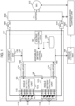
- the output of the single battery control unit 121b is transmitted by the signal communication unit 160 through the insulator 170 and through the input of the assembled battery control unit 150.
- the assembled battery control unit 150 and the single battery control units 121a and 121b are connected in a loop through the signal communication unit 160.
- This loop connection may be referred to as a daisy-chain connection, a bead-to-bead connection, or a potato-spinning connection.
- the configuration of the assembled battery control unit 150 will be described with reference to Figure 3 .
- This embodiment omits, for simplicity, the description of the processing details based on the diagnostic results related to the single batteries 111 and the error signals output when a communication error or the like occurs in the single battery management unit 120.
- the assembled battery control unit 150 consists of an SOC calculation unit 151, SOH calculation unit 152, model voltage calculation unit 153, correction factor calculation unit 154, and power limit value calculation unit 155.
- the SOC calculation unit 151 outputs SOC and SOCv using as inputs the average voltage of each of the single batteries 111 constituting the assembled battery 110, the current flowing in the assembled battery 110, and the model parameters output from the model voltage calculation unit 153 (described below). The details of the calculation process for SOC and SOCv are will be explained below.
- the SOH calculation unit 152 uses as inputs the SOC and SOCv output from the SOC calculation unit 151 and the model parameters output from the model voltage calculation unit 153 to calculate and output SOH which indicates the battery degradation rate.
- the model voltage calculation unit 153 outputs various model parameters and the voltage of the battery using the current, temperature, SOC, and SOH as inputs. SOC is obtained as a result of calculation performed in the SOC calculation unit 151.
- the various model parameters are parameters that constitute the voltage equivalent circuit model that predicts the battery's voltage.
- the voltage output from the model voltage calculation unit 153 includes the model voltage and OCV.
- the correction factor calculation unit 154 performs the correction factor calculation step.
- the correction factor calculation step is a step in which the correction factor k is calculated and output using the measured battery voltage and the model voltage and OCV calculated by the model voltage calculation unit 153 as inputs.
- the power limit value calculation unit 155 performs a power limit value calculation step.
- Embodiment 2 of the present invention will be described with reference to Figures 15 to 21 .
- the power limit value calculation unit 155' will be described with reference to Figure 16 .
- the difference from the power limit value calculation unit 155' of Embodiment 1 is that the correction factors kchg, kdis, and kvol expressed by Equations (14) to (16) are used as inputs which are used to calculate the allowable currents (Imax_c and Imax_d) and allowable powers (Pmax_c and Pmax_d) .
- a correction factor reflecting unit 155-1' will now be described.
- the correction factor reflecting unit 155-1' performs correction for the polarization resistance Rp and polarization voltage Vp, which are the same inputs as in Embodiment 1, using the correction factors kchg, kdis, and kvol.
- the internal resistance Rp'_chg and polarization voltage Vp'_chg for the available input current are calculated using kchg as expressed by the following equation (17).
- the internal resistance Rp'_dis and polarization voltage Vp'_dis for the available discharge current are calculated using kdis as expressed by the following equation (18) .
- the internal resistance Rp'_vol and polarization voltage Vp'_vol for voltage calculation are calculated using kvol as expressed by the following equation (19).
- the allowable current calculation unit 155-2' calculates the maximum available input current Imax_c and maximum available output current Imax_d of the battery by the following equations (20) and (21), using the model parameters including Rp and Vp that are corrected by Equations (17) and (18), and OCV as inputs.
- tcont and Ilimit in Equations (20) and (21) represent the upper current limit determined taking into account the assumed continuous energization time and the resistance of relays, fuses, and other components of the battery system.
- Embodiments 1 and 2 are explained a method of correcting the internal resistance component used for available input/output power calculation by calculating a correction factor according to the difference between the actual measured voltage, including the highest and lowest cell voltages, and the model voltage, and using the calculated correction factor k.
- This embodiment will explain a method of, more simply without correcting the internal resistance component, directly limiting the available input/output power to a smaller value when the correction factor exceeds a predetermined value.
- Embodiments 1 and 2 The description of this embodiment focuses on the differences from Embodiments 1 and 2, and omits explanations of the same configuration parts as in Embodiments 1 and 2.
- Figure 22 shows the functional configuration of a power limit value calculation unit 155" of this embodiment.
- the difference from the power limit value calculation unit 155' (shown in Figure 16 ) of Embodiment 2 is that, instead of inputting kchg, kdis, and kvol to the correction factor reflecting unit 155-1' like in the power limit value calculation unit 155' of Embodiment 2, this embodiment eliminates the correction factor reflecting unit 155-1' and kchg, kdis, and kvol are input to an allowable power limiting unit 155-4 which is disposed in a stage following the allowable power calculation unit 155-3'.
- the allowable power limiting unit 155-4 estimates the available input/output power limiting rate corresponding to the inputs: kchg, kdis, and kvol, reflects the estimated results in the outputs of the allowable power calculation unit 155-3': Wmax_c and Wmax_d, and outputs the final available input/output power (Pmax_c and Pmax_d).
- Pmax_c and Pmax_d are calculated using the following equations (26) and (27).
- P max _ c a in ⁇ N ⁇ I max _ c ⁇ OCV + I max c ⁇ R 0 + Rp ′ _ vol ⁇ 1 ⁇ exp ⁇ tcont ⁇ + Vp ′ _ vol ⁇ exp ⁇ tcont ⁇
- P max _ d a out ⁇ N ⁇ I max _ d ⁇ OCV ⁇ I max d ⁇ R 0 + Rp ′ _ vol ⁇ 1 ⁇ exp ⁇ tcont ⁇ + Vp ′ _ vol ⁇ exp ⁇ tcont ⁇
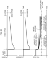
- Figure 24 shows the results of continuous input of power equivalent to the available output power to the battery
- Figure 25 shows the results of continuous input of power equivalent to the available input power to the battery.
- the horizontal axis represents, from the top row, time
- the vertical axes represent power, limiting factor, and voltage, respectively.
- the limiting factors (ain and aout) for limiting the available input/output power are calculated based on the correction factors kdis, kchg, and kvol that are described in Embodiment 2 and reflected in the available input/output power. It is thus possible to calculate the available input/output power that can prevent the voltages of all the batteries that are connected in series and constitute the secondary battery system from deviating from the upper and lower limit voltages.
- Embodiment 4 of the present invention will be described with reference to Figures 26 to 30 .
- the internal resistance can be estimated with high accuracy, and the model voltage and the actual measured voltage match, which means if the internal resistance calculation results can be directly reflected in the available input/output power calculation, it is not necessary to perform the correction processing as is explained in Embodiments 1 and 2 of the present invention. If the detection of internal resistance and the correction processing described in Embodiments 1 and 2 of the present invention are executed simultaneously, the internal resistance component utilized in the available input/output power calculation may fluctuate, and the available input/output power calculation results may show unexpected behavior such as oscillation.
- this embodiment will explain a method in which the correction factors described in Embodiments 1 and 2 are reflected only when the internal resistance calculation is out of the feasible range, and when the calculation is within the feasible range, the correction factors are not reflected to the internal resistance component to be utilized for available input/output power calculation.
- Embodiments 1, 2, and 3 The description of this embodiment focuses on the differences from Embodiments 1, 2, and 3, and omits explanations of the same configuration parts as in Embodiments 1, 2, and 3.
- the power limit value calculation unit 155" of this embodiment will be described with reference to Figure 28 .
- the difference from Embodiments 1 to 3 is that the judgement result, which is a new input to the power limit value calculation unit 155", is added to the input of a correction factor reflecting unit 155-1".
- the parameters (Rp'_chg, Vp'_chg, Rp'_dis, Vp'_dis, Rp'_vol, and Vp'_vol) that serve as outputs are calculated according to the judgement result, as expressed by the following equations (28) and (29).
- Figures 29 and 30 each show, from the top row, the waveforms of current, voltage, SOH, correction factor kchg, and maximum available output power Pmax_d versus time.
- Figure 29 shows the waveforms before the application of this embodiment
- Figure 30 shows the waveforms after the application of this embodiment.
- Figures 29 and 30 both assume the case where SOH is updated when the current value is input and energization is established for a predetermined number of seconds, and while the SOH calculation is being updated, the model voltage is also updated at the same time as it is updated. Since the SOH calculation may fluctuate due to errors (noise) in current or voltage measurement, in the SOH calculation ON sections in the drawing, the SOH behaves as if it is being updated while oscillating. Accordingly, the difference between the model voltage updated in the model voltage calculation unit 153, which uses SOH as an input, and the actual measured voltage will also oscillate, which makes the correction factor kchg also oscillate.
- the state of the secondary battery determined from the measured value related to the secondary battery is a voltage change in the internal resistance based on an actual measured voltage obtained by measuring the voltage of the secondary battery
- the state of the secondary battery calculated using the model related to the secondary battery is a voltage change in the internal resistance based on a model voltage determined using a voltage equivalent circuit model of the secondary battery
- the correction factor calculation unit determines, as the correction factor, the ratio between the voltage change in internal resistance based on the actual measured voltage and the voltage change in internal resistance based on the model voltage.
- the power limit value calculation unit included in the battery control device uses the correction factor to correct model parameters used to calculate the current and/or power that the secondary battery can input and output.
- the power limit value calculation unit corrects, among the model parameters, a time-dependent resistance component in the voltage equivalent circuit model of the secondary battery and polarization voltage in the voltage equivalent circuit model of the secondary battery, based on the correction factor.
- a correction factor map showing the relationship between an actual measured voltage difference, which is the difference between the actual measured voltage and open circuit voltage of the secondary battery, a model voltage difference, which is the difference between the model voltage and open circuit voltage of the secondary battery, and the correction factor may be constructed in advance, and the correction factor calculation unit may refer to the correction factor map based on the model voltage difference and the actual measured voltage difference during charging and discharging, thereby specifying the correction factor.
- the correction factor calculation unit may calculate the correction factor as a ratio between a polarization voltage calculated based on the voltage equivalent circuit model of the secondary battery and a polarization voltage calculated by subtracting the open circuit voltage and the voltage change due to time-independent resistance from the actual measured voltage.
- the correction factor can be obtained using any method.
- the correction factor calculation unit determines the correction factor used to calculate the current and/or power that can be input, using as the actual measured voltage the highest voltage among the voltages of the multiple secondary batteries.
- the correction factor calculation unit determines the correction factor used to calculate the current and/or power that can be output, using as the actual measured voltage the lowest voltage among the voltages of the multiple secondary batteries.
- the power limit value calculation unit can also calculate a limiting factor to limit the available input/output current and/or power of the secondary battery based on the correction factor, thereby limiting the available input/output current and/or power of the secondary battery to a smaller value.
- the disclosed battery control device further includes a SOH calculation unit 152 as a degradation rate calculation unit that calculates the degradation rate of the internal resistance of the secondary battery based on the current flowing in the secondary battery, voltage, and temperature; the degradation rate calculation unit determines that calculation of the degradation rate can be performed when the conditions for accurately calculating the degradation rate are satisfied; and upon determination that calculation of the degradation rate can be performed by the degradation rate calculation unit, the power limit value calculation unit suppresses correction based on the correction factor.
- a SOH calculation unit 152 as a degradation rate calculation unit that calculates the degradation rate of the internal resistance of the secondary battery based on the current flowing in the secondary battery, voltage, and temperature; the degradation rate calculation unit determines that calculation of the degradation rate can be performed when the conditions for accurately calculating the degradation rate are satisfied; and upon determination that calculation of the degradation rate can be performed by the degradation rate calculation unit, the power limit value calculation unit suppresses correction based on the correction factor.
- the degradation rate calculation unit determines whether or not to execute the calculation of the degradation rate depending on a condition based on at least one of the group consisting of: the charge rate, temperature, current, and current energization time related to the secondary battery.
- the above embodiments describe an example case in which a lithium-ion battery is used as a secondary battery, but the same charge-discharge control can be performed even when other secondary batteries are used.
- the present invention is not necessarily applied to electric vehicles but can also be applied to secondary batteries for any application.
- Calculation execution judgement unit 152-2...Internal resistance correction unit, 152-3...SOH calculation unit, 152-4...Energization time measuring unit, 153...Model voltage calculation unit, 154...Correction factor calculation unit, 155...Power limit value calculation unit, 155-1... Correction factor reflecting unit, 155-2... allowable current calculation unit, 155-3...Allowable power calculation unit, 155-4...Allowable power limiting unit, 180...Memory unit, 200...Vehicle control unit, 300, 310...Relay, 400... Inverter, 410...Motor, 420...Motor/inverter control unit
Landscapes
- Engineering & Computer Science (AREA)
- Physics & Mathematics (AREA)
- General Physics & Mathematics (AREA)
- General Chemical & Material Sciences (AREA)
- Manufacturing & Machinery (AREA)
- Chemical & Material Sciences (AREA)
- Chemical Kinetics & Catalysis (AREA)
- Electrochemistry (AREA)
- Power Engineering (AREA)
- Life Sciences & Earth Sciences (AREA)
- Sustainable Development (AREA)
- Sustainable Energy (AREA)
- Transportation (AREA)
- Mechanical Engineering (AREA)
- Microelectronics & Electronic Packaging (AREA)
- Secondary Cells (AREA)
Applications Claiming Priority (2)
| Application Number | Priority Date | Filing Date | Title |
|---|---|---|---|
| JP2022057675 | 2022-03-30 | ||
| PCT/JP2023/013391 WO2023190988A1 (fr) | 2022-03-30 | 2023-03-30 | Dispositif de commande de batterie et procédé de commande de batterie |
Publications (2)
| Publication Number | Publication Date |
|---|---|
| EP4503255A1 true EP4503255A1 (fr) | 2025-02-05 |
| EP4503255A4 EP4503255A4 (fr) | 2026-04-01 |
Family
ID=88202198
Family Applications (1)
| Application Number | Title | Priority Date | Filing Date |
|---|---|---|---|
| EP23780996.7A Pending EP4503255A4 (fr) | 2022-03-30 | 2023-03-30 | Dispositif de commande de batterie et procédé de commande de batterie |
Country Status (5)
| Country | Link |
|---|---|
| US (1) | US20240405299A1 (fr) |
| EP (1) | EP4503255A4 (fr) |
| JP (1) | JP7741971B2 (fr) |
| CN (1) | CN118044041A (fr) |
| WO (1) | WO2023190988A1 (fr) |
Families Citing this family (2)
| Publication number | Priority date | Publication date | Assignee | Title |
|---|---|---|---|---|
| TW202443944A (zh) * | 2022-12-16 | 2024-11-01 | 美商24M科技公司 | 用於最小化及預防電化電池中形成枝晶的系統及方法 |
| US12431545B1 (en) | 2024-03-26 | 2025-09-30 | 24M Technologies, Inc. | Systems and methods for minimizing and preventing dendrite formation in electrochemical cells |
Family Cites Families (5)
| Publication number | Priority date | Publication date | Assignee | Title |
|---|---|---|---|---|
| US9680320B2 (en) * | 2011-05-16 | 2017-06-13 | Hitachi Automotive Systems, Ltd. | Battery control apparatus |
| JP5842607B2 (ja) | 2011-12-28 | 2016-01-13 | トヨタ自動車株式会社 | 非水二次電池の制御装置および制御方法 |
| JP6383704B2 (ja) * | 2015-07-02 | 2018-08-29 | 日立オートモティブシステムズ株式会社 | 電池制御装置 |
| JP6787660B2 (ja) * | 2015-12-10 | 2020-11-18 | ビークルエナジージャパン株式会社 | 電池制御装置、動力システム |
| JP6615011B2 (ja) * | 2016-03-09 | 2019-12-04 | 日立オートモティブシステムズ株式会社 | 電池管理システム、電池システムおよびハイブリッド車両制御システム |
-
2023
- 2023-03-30 JP JP2024512857A patent/JP7741971B2/ja active Active
- 2023-03-30 WO PCT/JP2023/013391 patent/WO2023190988A1/fr not_active Ceased
- 2023-03-30 EP EP23780996.7A patent/EP4503255A4/fr active Pending
- 2023-03-30 CN CN202380013786.8A patent/CN118044041A/zh active Pending
- 2023-03-30 US US18/698,039 patent/US20240405299A1/en active Pending
Also Published As
| Publication number | Publication date |
|---|---|
| US20240405299A1 (en) | 2024-12-05 |
| CN118044041A (zh) | 2024-05-14 |
| JP7741971B2 (ja) | 2025-09-18 |
| WO2023190988A1 (fr) | 2023-10-05 |
| EP4503255A4 (fr) | 2026-04-01 |
| JPWO2023190988A1 (fr) | 2023-10-05 |
Similar Documents
| Publication | Publication Date | Title |
|---|---|---|
| EP2587621B1 (fr) | Circuit de commande d'unité de stockage d'énergie et appareil de stockage d'énergie | |
| US11124072B2 (en) | Battery control device and electric motor vehicle system | |
| US10955479B2 (en) | Battery control device | |
| JP3964635B2 (ja) | メモリー効果の検出方法およびその解消方法 | |
| CN113396503B (zh) | 电池控制装置 | |
| CN103548233B (zh) | 蓄电器控制电路 | |
| US9252624B2 (en) | Battery control device and battery system | |
| US10355325B2 (en) | Method for reusing vehicle rechargeable battery | |
| US8749201B2 (en) | Battery pack capacity learn algorithm | |
| CN104471414B (zh) | 电池控制装置 | |
| EP3410558A1 (fr) | Dispositif de commande de batterie | |
| CN115336084B (zh) | 电池控制装置及电池系统 | |
| JPWO2012140776A1 (ja) | 充電制御装置 | |
| EP4503255A1 (fr) | Dispositif de commande de batterie et procédé de commande de batterie | |
| US11899070B2 (en) | Battery control device | |
| CN116472634A (zh) | 电池控制装置以及电池系统 | |
| EP4507162A1 (fr) | Dispositif de commande de batterie et système de batterie | |
| JP5005610B2 (ja) | 蓄電装置の状態検出装置 |
Legal Events
| Date | Code | Title | Description |
|---|---|---|---|
| STAA | Information on the status of an ep patent application or granted ep patent |
Free format text: STATUS: THE INTERNATIONAL PUBLICATION HAS BEEN MADE |
|
| PUAI | Public reference made under article 153(3) epc to a published international application that has entered the european phase |
Free format text: ORIGINAL CODE: 0009012 |
|
| STAA | Information on the status of an ep patent application or granted ep patent |
Free format text: STATUS: REQUEST FOR EXAMINATION WAS MADE |
|
| 17P | Request for examination filed |
Effective date: 20240312 |
|
| AK | Designated contracting states |
Kind code of ref document: A1 Designated state(s): AL AT BE BG CH CY CZ DE DK EE ES FI FR GB GR HR HU IE IS IT LI LT LU LV MC ME MK MT NL NO PL PT RO RS SE SI SK SM TR |
|
| DAV | Request for validation of the european patent (deleted) | ||
| DAX | Request for extension of the european patent (deleted) | ||
| A4 | Supplementary search report drawn up and despatched |
Effective date: 20260303 |
|
| RIC1 | Information provided on ipc code assigned before grant |
Ipc: H01M 10/44 20060101AFI20260225BHEP Ipc: G01R 31/382 20190101ALI20260225BHEP Ipc: G01R 31/385 20190101ALI20260225BHEP Ipc: G01R 31/389 20190101ALI20260225BHEP Ipc: H01M 10/48 20060101ALI20260225BHEP Ipc: H02J 7/00 20060101ALI20260225BHEP Ipc: B60L 3/12 20060101ALI20260225BHEP Ipc: B60L 58/12 20190101ALI20260225BHEP Ipc: B60L 58/13 20190101ALI20260225BHEP Ipc: B60L 58/14 20190101ALI20260225BHEP Ipc: B60L 58/16 20190101ALI20260225BHEP |
|
| RIN1 | Information on inventor provided before grant (corrected) |
Inventor name: NAKAO, RYOHEI |