EP4503261A1 - Élément de batterie, batterie et appareil électrique - Google Patents
Élément de batterie, batterie et appareil électrique Download PDFInfo
- Publication number
- EP4503261A1 EP4503261A1 EP23866825.5A EP23866825A EP4503261A1 EP 4503261 A1 EP4503261 A1 EP 4503261A1 EP 23866825 A EP23866825 A EP 23866825A EP 4503261 A1 EP4503261 A1 EP 4503261A1
- Authority
- EP
- European Patent Office
- Prior art keywords
- sampling module
- battery cell
- mounting region
- plug
- conductor
- Prior art date
- Legal status (The legal status is an assumption and is not a legal conclusion. Google has not performed a legal analysis and makes no representation as to the accuracy of the status listed.)
- Pending
Links
Images



Classifications
-
- H—ELECTRICITY
- H01—ELECTRIC ELEMENTS
- H01M—PROCESSES OR MEANS, e.g. BATTERIES, FOR THE DIRECT CONVERSION OF CHEMICAL ENERGY INTO ELECTRICAL ENERGY
- H01M10/00—Secondary cells; Manufacture thereof
- H01M10/42—Methods or arrangements for servicing or maintenance of secondary cells or secondary half-cells
- H01M10/425—Structural combination with electronic components, e.g. electronic circuits integrated to the outside of the casing
-
- G—PHYSICS
- G01—MEASURING; TESTING
- G01R—MEASURING ELECTRIC VARIABLES; MEASURING MAGNETIC VARIABLES
- G01R31/00—Arrangements for testing electric properties; Arrangements for locating electric faults; Arrangements for electrical testing characterised by what is being tested not provided for elsewhere
- G01R31/36—Arrangements for testing, measuring or monitoring the electrical condition of accumulators or electric batteries, e.g. capacity or state of charge [SoC]
- G01R31/382—Arrangements for monitoring battery or accumulator variables, e.g. SoC
- G01R31/3835—Arrangements for monitoring battery or accumulator variables, e.g. SoC involving only voltage measurements
-
- H—ELECTRICITY
- H01—ELECTRIC ELEMENTS
- H01M—PROCESSES OR MEANS, e.g. BATTERIES, FOR THE DIRECT CONVERSION OF CHEMICAL ENERGY INTO ELECTRICAL ENERGY
- H01M50/00—Constructional details or processes of manufacture of the non-active parts of electrochemical cells other than fuel cells, e.g. hybrid cells
- H01M50/10—Primary casings; Jackets or wrappings
- H01M50/147—Lids or covers
-
- H—ELECTRICITY
- H01—ELECTRIC ELEMENTS
- H01M—PROCESSES OR MEANS, e.g. BATTERIES, FOR THE DIRECT CONVERSION OF CHEMICAL ENERGY INTO ELECTRICAL ENERGY
- H01M50/00—Constructional details or processes of manufacture of the non-active parts of electrochemical cells other than fuel cells, e.g. hybrid cells
- H01M50/10—Primary casings; Jackets or wrappings
- H01M50/172—Arrangements of electric connectors penetrating the casing
-
- H—ELECTRICITY
- H01—ELECTRIC ELEMENTS
- H01M—PROCESSES OR MEANS, e.g. BATTERIES, FOR THE DIRECT CONVERSION OF CHEMICAL ENERGY INTO ELECTRICAL ENERGY
- H01M50/00—Constructional details or processes of manufacture of the non-active parts of electrochemical cells other than fuel cells, e.g. hybrid cells
- H01M50/50—Current conducting connections for cells or batteries
- H01M50/543—Terminals
- H01M50/547—Terminals characterised by the disposition of the terminals on the cells
- H01M50/55—Terminals characterised by the disposition of the terminals on the cells on the same side of the cell
-
- H—ELECTRICITY
- H01—ELECTRIC ELEMENTS
- H01M—PROCESSES OR MEANS, e.g. BATTERIES, FOR THE DIRECT CONVERSION OF CHEMICAL ENERGY INTO ELECTRICAL ENERGY
- H01M50/00—Constructional details or processes of manufacture of the non-active parts of electrochemical cells other than fuel cells, e.g. hybrid cells
- H01M50/50—Current conducting connections for cells or batteries
- H01M50/569—Constructional details of current conducting connections for detecting conditions inside cells or batteries, e.g. details of voltage sensing terminals
-
- G—PHYSICS
- G01—MEASURING; TESTING
- G01R—MEASURING ELECTRIC VARIABLES; MEASURING MAGNETIC VARIABLES
- G01R31/00—Arrangements for testing electric properties; Arrangements for locating electric faults; Arrangements for electrical testing characterised by what is being tested not provided for elsewhere
- G01R31/36—Arrangements for testing, measuring or monitoring the electrical condition of accumulators or electric batteries, e.g. capacity or state of charge [SoC]
- G01R31/364—Battery terminal connectors with integrated measuring arrangements
-
- H—ELECTRICITY
- H01—ELECTRIC ELEMENTS
- H01M—PROCESSES OR MEANS, e.g. BATTERIES, FOR THE DIRECT CONVERSION OF CHEMICAL ENERGY INTO ELECTRICAL ENERGY
- H01M10/00—Secondary cells; Manufacture thereof
- H01M10/42—Methods or arrangements for servicing or maintenance of secondary cells or secondary half-cells
- H01M10/425—Structural combination with electronic components, e.g. electronic circuits integrated to the outside of the casing
- H01M2010/4278—Systems for data transfer from batteries, e.g. transfer of battery parameters to a controller, data transferred between battery controller and main controller
-
- Y—GENERAL TAGGING OF NEW TECHNOLOGICAL DEVELOPMENTS; GENERAL TAGGING OF CROSS-SECTIONAL TECHNOLOGIES SPANNING OVER SEVERAL SECTIONS OF THE IPC; TECHNICAL SUBJECTS COVERED BY FORMER USPC CROSS-REFERENCE ART COLLECTIONS [XRACs] AND DIGESTS
- Y02—TECHNOLOGIES OR APPLICATIONS FOR MITIGATION OR ADAPTATION AGAINST CLIMATE CHANGE
- Y02E—REDUCTION OF GREENHOUSE GAS [GHG] EMISSIONS, RELATED TO ENERGY GENERATION, TRANSMISSION OR DISTRIBUTION
- Y02E60/00—Enabling technologies; Technologies with a potential or indirect contribution to GHG emissions mitigation
- Y02E60/10—Energy storage using batteries
Definitions
- This application relates to the field of battery technologies, and in particular to a battery cell, a battery, and an electric apparatus.
- a battery management system (BATTERY MANAGEMENT SYSTEM, BMS for short) is usually provided.
- status signals (such as voltage signals and temperature signals) of a battery cell are transmitted to CMC (Cell Monitoring Circuit, cell monitoring circuit in English) for collection through a flexible circuit board and wiring harness, and the collected signals are transmitted to BMU (Battery Management Unit, battery management unit in English).
- CMC Cell Monitoring Circuit, cell monitoring circuit in English
- BMU Battery Management Unit
- this application provides a battery cell including: a housing; an electrode terminal; at least one conductor, disposed on the housing and electrically connected to the electrode terminal; and a sampling module, connected to the housing and electrically connected to the conductor.
- the sampling module is connected to the housing and electrically connected to the conductor.
- the conductor is disposed on the housing and electrically connected to the corresponding electrode terminal. Therefore, when status signals from the battery cell are collected, signals from at least one collection point of the sampling module are directly transmitted by the electrode terminal.
- the sampling module is integrated on the housing, and at least one conductor is electrically connected to the electrode terminal, which changes the conventional method of transmitting signals to CMC through a flexible circuit board and wiring harness, avoids the transmission of status signals from being affected by factors such as interference coupling and wiring short-circuiting, shortens the signal transmission path, and improves the reliability of signal collection by the sampling module. Moreover, during signal collection, there is no need to additionally configure a flexible circuit and wiring harness, which greatly reduces the cost of signal collection.
- the sampling module has at least one conductive portion, and when the sampling module is connected to the housing, the conductive portion is electrically connected to the conductor. In this way, during assembly, electrical conduction between the sampling module and the conductor can be achieved by simply connecting the conductive portion to the conductor, which helps to improve assembly efficiency.
- the housing is provided with a connecting member, the connecting member is electrically connected to the conductor, and when the sampling module is connected to the housing, the conductive portion is electrically connected to the connecting member.
- the corresponding connecting member is provided on the housing, so that during assembly, the electrical conduction between the sampling module and the conductor can be achieved by simply connecting the conductive portion to the connecting member.
- the housing has a mounting region, the connecting member is located in the mounting region, and the sampling module is mounted in the mounting region.
- the mounting region is provided on the housing, so that the mounting position of the sampling module is defined, thereby maintaining the consistency of the position of the sampling module in the battery cell.
- the sampling module is detachably mounted in the mounting region. In this way, the sampling module designed to be detachably mounted in the mounting region, so that the sampling module can be replaced, facilitating the maintenance of the battery cell.
- the battery cell further includes a limiting structure disposed on the housing, where the limiting structure is constructed to limit the sampling module within the mounting region and to crimp the conductive portion onto the connecting member accordingly.
- the limiting structure is provided, so that the sampling module is stably fixed in the mounting region, which helps to improve the reliability of signal collection.
- the limiting structure is used to directly crimp the conductive portion onto the connecting member, which not only helps to improve the electrical connection strength but also facilitates the electrical connection between the conductive portion and the connecting member, improving assembly efficiency.
- the limiting structure includes a first limiting piece, where the first limiting piece and the connecting member are spaced apart within the mounting region along a preset direction, the preset direction is perpendicular to a thickness direction of the housing in the mounting region, the first limiting piece limits one end of the sampling module in the preset direction, and the second limiting piece limits a side face of the sampling module facing away from the mounting region.
- the first limiting piece is used, so that the sampling module is effectively limited in at least one direction, ensuring stable crimping of the conductive portion and the connecting member, thereby improving the reliability of collection.
- the limiting structure further includes a second limiting piece, where the second limiting piece limits a side face of the sampling module facing away from the mounting region.
- the first limiting piece and the second limiting piece are used, so that the sampling module is effectively limited in at least two directions, ensuring stable crimping of the conductive portion and the connecting member, thereby improving the reliability of collection.
- At least one of the first limiting piece and the second limiting piece moves or deforms to allow the sampling module to be limited or released within the mounting region.
- the sampling module can be limited or released by deforming or moving at least one of the first limiting piece and the second limiting piece, facilitating the mounting and removal of the sampling module.
- the mounting region is provided with a first concave portion
- the first limiting piece is disposed on an inner wall of the first concave portion and at least partially protrudes from the first concave portion
- the first limiting piece is constructed to be elastically pressed into the first concave portion.
- the first limiting piece is designed to be elastically pressed into the first concave portion, so that the sampling module can be more conveniently mounted into the mounting region, improving assembly efficiency.
- the first limiting piece at least partially protrudes from the first concave portion, so that the sampling module mounted in the mounting region can abut against the first limiting piece, ensuring stable fixation of the sampling module.
- the mounting gap is constructed to allow the sampling module squeezing the first limiting piece to move along the preset direction, and when the sampling module moves to a point where the conductive portion is crimped onto the connecting member, the first limiting piece springs up and limits one end of the sampling module.
- the mounting gap is provided between the second limiting piece and the mounting region, so that during the mounting of the sampling module, the sampling module can be limited and electrically connected by simply moving in the mounting gap along the preset direction, making the mounting of the sampling module more convenient.
- the sampling module is provided with a notch, where the notch is configured for the sampling module to pass through the second limiting piece. In this way, the notch is used to avoid interference from the second limiting piece, ensuring the smooth placement of the sampling module into the mounting region, thereby better completing the assembly of the sampling module.
- the connecting member includes a connecting piece electrically connected to the conductor, the mounting region is provided with a second concave portion spaced apart from the first concave portion along the preset direction, and the connecting piece is elastically disposed on an inner wall of the second concave portion and at least partially protrudes from the second concave portion.
- the connecting piece is elastically disposed on the inner wall of the second concave portion and at least partially protrudes from the second concave portion, which ensures stable contact between the connecting piece and the conductive portion, and avoids structural damage caused by rigid contact therebetween.
- the connecting piece in the same connecting member, is provided in at least two, and all the connecting pieces are spaced apart on the inner wall of the second concave portion and electrically connected to the same conductor. In this way, a plurality of connecting pieces are arranged in the second concave portion, so that the number of contact points between the connecting member and the conductive portion is increased, which helps to ensure stable electrical conduction therebetween.
- the limiting structure further includes a third limiting piece, where the third limiting piece is located at an end of the mounting region close to the connecting member, and a limiting gap is left between the third limiting piece and the mounting region. In this way, the limiting gap is left between the third limiting piece and the mounting region.
- the connecting member is electrically plugged in the corresponding conductive portion.
- the connecting member is electrically plugged in the conductive portion, which not only ensures stable electrical connection between the connecting member and the conductive portion, but also implements detachable connection between the sampling module and the mounting region depending on their electrical plugging, facilitating assembly and maintenance.
- the conductive portion includes a plug-in protrusion protruding from a surface of the sampling module, where the plug-in protrusion is plug-fitted with the connecting member. In this way, the plugging method is used, so that the sampling module is quickly electrically connected to the connecting member, improving assembly efficiency.
- the connecting member includes a first clamping piece and second clamping piece disposed in the mounting region, where the first clamping piece and the second clamping piece are configured for the plug-in protrusion to be plugged in.
- the connecting member is designed as the first clamping piece and the second clamping piece, so that the conductive portion can be stably plugged in the connecting member, which ensures good electrical contact and helps to improve the reliability of signal collection.
- the connecting member includes a conductive elastic piece disposed in the mounting region, a plug-in hole extending along the thickness direction of the housing in the mounting region is formed in the mounting region, the plug-in protrusion is plug-fitted with the plug-in hole, the conductive elastic piece is disposed on a side wall of the plug-in hole and abuts against the plug-in protrusion under the elastic force of the conductive elastic piece, and the conductor is electrically connected to the plug-in protrusion through the conductive elastic piece.
- the plug-in protrusion is plug-fitted with the plug-in hole, and under the elastic force of the conductive elastic piece, the plug-in protrusion always maintains electrical connection with the conductive elastic piece, which has good electrical contact, so as to improve the reliability of signal collection by the sampling module.
- the battery cell further includes a fastener
- the sampling module is provided with a through hole extending along the thickness direction of the housing, and the fastener passes through the through hole to be connected to the mounting region of the housing.
- the sampling module and the housing can be disassembled and assembled through the fastener, which provides a simple structure and makes assembly and disassembly convenient.
- the electrode terminal, the plug-in protrusion, the conductor, and plug-in hole are all provided in two, where the two plug-in protrusions and the two plug-in holes are both spaced apart along a preset direction, the preset direction is perpendicular to the thickness direction of the housing in the mounting region, one electrode terminal is electrically connected to one conductive elastic piece through one conductor, one conductive elastic piece is electrically connected to one plug-in protrusion, the other electrode terminal is electrically connected to the other conductive elastic piece through the other conductor, and the other conductive elastic piece is electrically connected to the other plug-in protrusion.
- the electrical connection between the two electrode terminals of the battery cell and the two plug-in protrusions of the sampling module can be achieved, and the reliability of the electrical connection between the electrode terminals and the sampling module can be improved through such arrangement of the conductive elastic pieces.
- the number of conductive elastic pieces in the plug-in hole is two, and the two conductive elastic pieces are located on opposite sides of the plug-in protrusion.
- the housing is provided with a mounting groove, where the mounting region is a bottom wall of the mounting groove.
- the mounting region is constructed as the bottom wall of the mounting groove, so that the mounting region have a certain height difference from the surface of the housing, which makes the mounting of the sampling module more stable and also avoids the sampling module protruding from the surface of the housing, leading to the ineffective utilization of the space in a height direction of the battery cell.
- the housing includes a shell and an end cover covering the shell, where the sampling module, the electrode terminal, and the conductor are all connected to the end cover.
- the sampling module and the conductor are both arranged on the end cover, so that the conductor is more easily electrically connected to the electrode terminal on the end cover, which shortens the transmission path of the electrical signal and helps to improve the reliability of signal collection by the sampling module.
- the end cover is provided with a through hole extending along a thickness direction of the end cover, where the through hole is configured for the mounting of the electrode terminal, and one end of the conductor disposed on the end cover extends into the through hole. In this way, one end of the conductor extends into the through hole, which makes the electrical connection between the electrode terminal and the conductor more convenient and helps to improve the assembly efficiency of the battery cell.
- the conductor is embedded in the end cover, and one end of the conductor extends and passes through a wall of the through hole.
- embedding the conductor in the end cover avoids the conductor from being directly exposed on the surface of the end cover, which can easily cause structural interference inside the battery cell; and in addition, embedding the conductor in the end cover can also implement the insulation of the outer surface of the conductor.
- the numbers of through holes and conductors are both two, the two conductors are both disposed on the end cover, and one ends of the two conductors respectively extend into the two through holes. In this way, one ends of the conductors extend into the corresponding through holes, so that the conductors can be electrically connected to the electrode terminals and transmit status signals through the electrode terminals, which further improves the reliability of signal collection.
- this application provides a battery, including the foregoing battery cell.
- this application provides an electric apparatus, including the foregoing battery, where the battery is configured to provide electric energy.
- the term "and/or" is only an associative relationship for describing associated objects, indicating that three relationships may be present.
- a and/or B may indicate the following three cases: presence of only A, presence of both A and B, and presence of only B.
- a character "/" in this specification generally indicates an "or" relationship between contextually associated objects.
- a plurality of means more than two (inclusive).
- a plurality of groups means more than two (inclusive) groups
- a plurality of pieces means more than two (inclusive) pieces.
- the technical terms “mounting”, “connection”, “joining”, and “fastening” should be understood in their general senses. For example, they may refer to a fixed connection, a detachable connection, or an integrated connection, may refer to a mechanical connection or an electrical connection, and may refer to a direct connection, an indirect connection through an intermediate medium, an internal connection between two elements, or an interaction between two elements. Persons of ordinary skill in the art can understand specific meanings of these terms in this application as appropriate to specific situations.
- Traction batteries have been not only used in energy storage power supply systems such as hydroelectric power plants, thermal power plants, wind power plants, and solar power plants, but also widely used in many other fields including electric transportation tools such as electric bicycles, electric motorcycles, and electric vehicles, military equipment, and aerospace. With the continuous expansion of application fields of traction batteries, market demands for traction batteries are also increasing.
- a battery management system (BATTERY MANAGEMENT SYSTEM, BMS for short) is usually provided.
- a conventional battery management system includes a BMU (Battery Management Unit, battery management unit in English) and a CMC (Cell Monitoring Circuit, cell monitoring circuit in English).
- BMU Battery Management Unit
- CMC Cell Monitoring Circuit, cell monitoring circuit in English.
- the conventional sampling module is integrated with the CMC, when status signals of the battery cell are collected, it is necessary to additionally transmit the status signals (such as voltage signals and temperature signals) of the battery cell to the CMC for collection through a flexible circuit board and wiring harness, and the collected signals are then transmitted to the BMU.
- the CMC integrated with the sampling module relies on the flexible circuit board and wiring harness to collect signals from the battery cell, and the collected signals are easily affected by the flexible circuit board and wiring harness, for example, interference coupling and wiring harness short-circuiting, resulting in reduced reliability of the signals collection.
- using the flexible circuit board and wiring harness to transmit signals requires additional arrangement of the flexible circuit board and wiring harness, resulting in increased cost of signal collection.
- this application provides a battery cell.
- a sampling module is connected to a housing and collects the status signals of the battery cell using a conductor.
- the conductor is disposed on an end cover and configured to be electrically connected to an electrode terminal.
- the sampling module is connected to the housing and electrically connected to the conductor. At least one conductor is disposed on the housing and electrically connected to the electrode terminal. Therefore, when status signals from the battery cell are collected, signals from at least one collection point of the sampling module are directly transmitted by the electrode terminal.
- the sampling module is integrated on the housing, and at least one conductor is electrically connected to the electrode terminal, which changes the conventional method of transmitting signals to CMC through a flexible circuit board and wiring harness, avoids the transmission of status signals from being affected by factors such as interference coupling and wiring short-circuiting, shortens the signal transmission path, and improves the reliability of signal collection by the sampling module. Moreover, during signal collection, there is no need to additionally configure a flexible circuit and wiring harness, which greatly reduces the cost of signal collection.
- the battery cell disclosed in the embodiments of this application may be used without limitation in an electric apparatus such as a vehicle, a ship, or an aircraft.
- the battery cell, battery, and the like disclosed in this application may be used to constitute a power supply system of that electric apparatus.
- An embodiment of this application provides an electric apparatus that uses a battery as a power source.
- the electric apparatus may be but is not limited to a mobile phone, a tablet, a laptop computer, an electric toy, an electric tool, an electric bicycle, an electric car, a ship, or a spacecraft.
- the electric toy may be a fixed or mobile electric toy, for example, a game console, an electric toy car, an electric toy ship, and an electric toy airplane.
- the spacecraft may include an airplane, a rocket, a space shuttle, a spaceship, and the like.
- an electric apparatus for ease of description, an electric apparatus according to an embodiment of this application being a vehicle 1000 is used as an example for description of the following embodiments.
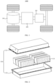
- FIG. 1 is a schematic structural diagram of a vehicle 1000 according to some embodiments of this application.
- the vehicle 1000 may be a fossil fuel vehicle, a natural-gas vehicle, or a new energy vehicle, where the new energy vehicle may be a battery electric vehicle, a hybrid electric vehicle, a range-extended vehicle, or the like.
- the vehicle 1000 is provided with a battery 100 inside, where the battery 100 may be arranged at the bottom, front, or rear of the vehicle 1000.
- the battery 100 may be configured to supply power to the vehicle 1000.
- the battery 100 may be used as an operational power supply for the vehicle 1000.
- the vehicle 1000 may further include a controller 200 and a motor 300, where the controller 200 is configured to control the battery 100 to supply power to the motor 300, for example, to satisfy power needs of start, navigation, and driving of the vehicle 1000.
- the battery 100 can be used as not only the operational power source for the vehicle 1000 but also a driving power source for the vehicle 1000, replacing or partially replacing fossil fuel or natural gas to provide driving traction for the vehicle 1000.
- FIG. 2 is an exploded view of a battery 100 according to some embodiments of this application.
- the battery 100 includes a box 120 and a battery cell 110, where the battery cell 110 is accommodated in the box 120.
- the box 120 is configured to provide an accommodating space for the battery cell 110.
- the box 120 may be a variety of structures.
- the box 120 may include a first portion 121 and a second portion 122. The first portion 121 and the second portion 122 fit with each other so that the first portion 121 and the second portion 122 jointly define an accommodating space for accommodating the battery cell 110.
- the second portion 122 may be a hollow structure with an opening at one end, the first portion 121 may be a plate structure, and the first portion 121 is engaged with the opening side of the second portion 122, so that the first portion 121 and the second portion 122 jointly define the accommodating space; or the first portion 121 and the second portion 122 may both be hollow structures with an opening on one side, and the opening side of the first portion 121 is engaged with the opening side of the second portion 122.
- the box 120 formed by the first portion 121 and the second portion 122 may be in various shapes, for example, cylinder or cuboid.
- the battery cell 110 may be provided in plurality, and the plurality of battery cells 110 may be connected in series, parallel, or series-parallel, where being connected in series-parallel means a combination of series and parallel connections of the plurality of battery cells 110.
- the plurality of battery cells 110 may be directly connected in series, parallel, or series-parallel, and an entirety constituted by the plurality of battery cells 110 is accommodated in the box 120.
- the battery 100 may alternatively be formed by connecting a plurality of battery cells 110 in series, parallel, or series-parallel first to constitute a battery 100 module, then connecting a plurality of battery 100 modules in series, parallel, or series-parallel to constitute an entirety, and accommodating the entirety in the box 120.
- the battery 100 may further include other structures.
- the battery 100 may further include a busbar configured to implement electrical connection between the plurality of battery cells 110.
- Each battery cell 110 may be a secondary battery or a primary battery, or may be a lithium-sulfur battery 100, a sodium-ion battery, or a magnesium-ion battery, but is not limited thereto.
- the battery cell 110 may be cylindrical, flat, cuboid, or in other shapes.
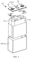
- FIG. 3 is a schematic structural exploded view of a battery cell 110 according to some embodiments of this application.
- the battery cell 110 refers to a smallest element constituting the battery 100.
- the battery cell 110 includes an end cover 11, a shell 20, an electrode assembly 30, and other functional components.
- the end cover 11 refers to a component that covers an opening of the shell 20 to separate an internal environment of the battery cell 110 from an external environment.
- a shape of the end cover 11 may be adapted to a shape of the shell 20 so that the end cover 11 fits with the shell 20.
- the end cover 11 may be made of a material with certain hardness and strength (for example, aluminum alloy), so that the end cover 11 is less likely to deform when subjected to squeezing or collision, allowing the battery cell 110 to have higher structural strength and enhanced safety performance.
- the end cover 11 may be provided with functional components such as an electrode terminal.
- the electrode terminal may be configured to be electrically connected to the electrode assembly 30 for outputting or inputting electrical energy of the battery cell 110.
- the end cover 11 may further be provided with a pressure relief mechanism for releasing internal pressure when the internal pressure or a temperature of the battery cell 110 reaches a threshold.
- the end cover 11 may also be made of various materials, such as copper, iron, aluminum, stainless steel, aluminum alloy, and plastic, which are not particularly limited in the embodiments of this application.
- an insulator may also be provided on an inner side of the end cover 11. The insulator may be configured to separate an electrically connected component in the shell 20 from the end cover 11 so as to reduce the risk of short circuit.
- the insulator may be made of plastic, rubber, or the like.
- the shell 20 is an assembly configured to form an internal environment of the battery cell 110 together with the end cover 11, where the formed internal environment may be configured to accommodate the electrode assembly 30, an electrolyte, and other components.
- the shell 20 and the end cover 11 may be separate components, an opening may be provided on the shell 20, and the end cover 11 covers the opening to form the internal environment of the battery cell 110.
- the end cover 11 and the shell 20 may alternatively be integrated.
- the end cover 11 and the shell 20 may form a shared connection surface before other components are placed inside the housing, and then the end cover 11 covers the shell 20 when the inside of the shell 20 needs to be enclosed.
- the shell 20 may be of various shapes and sizes, such as a cuboid shape, a cylindrical shape, and a hexagonal prism shape.
- a shape of the shell 20 may be determined according to a specific shape and size of the electrode assembly 30.
- the shell 20 may be made of various materials, such as copper, iron, aluminum, stainless steel, aluminum alloy, and plastic, which are not particularly limited in the embodiments of this application.
- the electrode assembly 30 is a component in the battery cell 110 in which electrochemical reactions take place.
- the shell 20 may include one or more electrode assemblies 30.
- the electrode assembly 30 is mainly formed by winding or stacking a positive electrode plate and a negative electrode plate, with a separator typically disposed between the positive electrode plate and the negative electrode plate. Portions of the positive electrode plate and the negative electrode plate that have active substances constitute a body portion of the electrode assembly 30, while portions of the positive electrode plate and the negative electrode plate that have no active substance separately constitute a tab.
- a positive electrode tab and a negative electrode tab may both be located at one end of the body portion or be located at two ends of the body portion respectively.
- this application provides a battery cell 110.
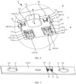
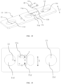
- the battery cell includes a housing 10, an electrode terminal 40, a conductor 13, and a sampling module 12. At least one conductor 13 is disposed on the housing 10 and electrically connected to the electrode terminal 40.
- the sampling module 12 is connected to the housing 10 and electrically connected to the conductor 13.
- the sampling module 12 refers to a device for collecting status signals of the battery cell 110, that is, a device that can receive status signals from the battery cell 110 through the conductor 13 and has functions such as storing and processing the status signals, and the processed status signals are transmitted to BMU.
- the status signals refer to status information exhibited by the battery cell 110, for example, temperature signals, voltage signals, pressure signals from the battery cell 110.
- the sampling module 12 and the BMU communicate with each other in many ways. For example, the communication modes therebetween may be but are not limited to infrared communication, Bluetooth transmission, and ZigBee (ZigBee protocol).
- the sampling module 12 may be designed as a PCB board, on which an integrated chip with a plurality of collection channels such as a voltage collection channel and a temperature collection channel can be arranged.
- the specific circuit structure of the sampling module 12 is not the object of improvement in this application. Therefore, for the specific circuit structure of the sampling module 12, reference may be directly made to existing products or literature, such as a collection module in CMC, and details are not specifically introduced herein.
- the sampling module 12 can be mounted on the housing 10 in many ways.
- the mounting methods may be, but are not limited to, welding, clamping, riveting, bolt connection, pin connection, and adhesive bonding.
- the housing 10 refers to an external packaging structure of the battery cell 110.
- the housing 10 may be provided with the structure of the end cover 11, or may not be provided with the structure of the end cover 11, and in this case, the battery cell 110 is a cell structure without the end cover 11.
- the conductor 13 refers to a structure that can transmit the status signals from the battery cell 110 to the sampling module 12 in the form of current or voltage.
- the conductor 13 may be provided in one or plurality. When the conductor 13 is provided in one, the conductor 13 is electrically connected to one electrode of the sampling module 12, and another electrode can be connected in other electrical connection ways, for example, directly welded to a collected component or electrically connected through other structures.
- the conductor 13 is provided in two, when connected to the sampling module 12, one conductor 13 is connected to a positive electrode terminal of the sampling module 12, and the other conductor 13 is connected to a negative electrode terminal of the sampling module 12, forming a sampling circuit loop.
- the conductor 13 may be, but is not limited to, a wire, a conductive metal sheet (such as a copper sheet or an aluminum sheet).
- the conductor 13 on the housing 10 may be directly arranged on a surface of the housing 10; or may be arranged inside the housing 10, that is, embedded inside the housing 10. When the conductor 13 is arranged on a surface of the housing 10, an outer surface of the conductor 13 needs to be insulated.
- one of the two conductors 13 may be disposed on the housing 10 and electrically connected to the electrode terminal 40; the other conductor 13 may be connected to the electrode terminal 40, or may be not connected to the electrode terminal 40, for example, the conductor 13 is directly connected to a tab of the electrode assembly 30 in the battery cell 110, or the conductor 13 is connected to a connecting sheet in a pack assembly.
- the signal transmission efficiency and path can both be effectively optimized, greatly reducing the influence of factors such as interference coupling and wiring harness short-circuiting, and improving the reliability of collection.
- the sampling module 12 is integrated on the housing 10, and at least one conductor 13 is electrically connected to the electrode terminal 40, which changes the conventional method of transmitting signals to the CMC using a flexible circuit board and wiring harness, avoids the influence of factors such as interference coupling and wiring short-circuiting on the transmission of status signals, shortens the signal transmission path, and improves the reliability of signal collection by the sampling module 12. Moreover, during signal collection, there is no need to additionally configure the flexible circuit and wiring harness, which greatly reduces the cost of signal collection.
- the sampling module 12 has at least one conductive portion 12a, and when the sampling module 12 is connected to the housing 10, the conductive portion 12a is electrically connected to the corresponding conductor 13.
- the conductive portion 12a refers to an electrical connection terminal on the sampling module 12, and is a component for inputting signals inward or outputting signals outward.
- the conductive portion 12a on the sampling module 12 may be designed as a socket structure or a plug structure, or may be designed as a pin or a gold finger structure.
- the conductive portion 12a is provided in two, and the two conductive portions 12a are electrically connected to the two conductors 13 in one-to-one correspondence.
- the electrical conduction between the sampling module 12 and the conductor 13 can be achieved by simply connecting the conductive portion 12a to the conductor 13, which helps to improve assembly efficiency.
- the housing 10 is provided with a connecting member 15, where the connecting member 15 is electrically connected to the conductor 13.
- the conductive portion 12a is electrically connected to the connecting member 15.
- the connecting member 15 refers to a component that achieves electrical conduction between the conductor 13 and the conductive portion 12a.
- the connecting member 15 and the conductive portion 12a are connected in many ways.
- the connection therebetween may be crimping, welding, plugging, bolt connection, or winding.
- the connection between the connecting member 15 and the conductor 13 may alternatively be, but is not limited to, crimping, welding, plugging, bolt connection, or winding.
- the connecting member 15 is provided in two.
- the conductive portion 12a is electrically connected to the corresponding conductor 13 through the connecting member 15.
- the housing 10 is provided with the corresponding connecting member 15, so that during assembly, the electrical conduction between the sampling module 12 and the conductor 13 can be implemented by simply connecting the conductive portion 12a to the connecting member 15, which helps to improve assembly efficiency.
- the housing 10 has a mounting region 11a.
- the connecting member 15 is located in the mounting region 11a, and the sampling module 12 is mounted in the mounting region 11a.
- the mounting region 11a is a region of a certain area on the housing 10, and this region may be a region directly on the surface of the housing 10, or the bottom of a recessed region on the housing 10.
- the housing 10 is provided with the mounting region 11a, so that the mounting position of the sampling module 12 is defined, thereby maintaining the consistency of the position of the sampling module 12 in the battery cell 110.
- the battery cell 110 further includes a limiting structure 14 disposed on the housing 10, where the limiting structure 14 is constructed to limit the sampling module 12 within the mounting region 11a and to crimp the conductive portion 12a onto the connecting member 15 accordingly.
- the limiting structure 14 refers to a component that can fix the sampling module 12 in the mounting region 11a and crimp the conductive portion 12a onto the connecting member 15 using a limiting force on the sampling module 12 to achieve electrical conduction. While fixing the sampling module 12, the limiting structure 14 can also allow the sampling module 12 to be entirely disassembled from the mounting region 11a. For example, at least part of the limiting structure 14 can rotate, move, or deform, causing at least one part of the sampling module 12 to lose its limiting function and enabling the sampling module 12 to release from the mounting region 11a.
- the conductive portion 12a is crimped onto the connecting member 15, which should be understood as follows: When the sampling module 12 is limited within the mounting region 11a by the action of the limiting structure 14, the conductive portion 12a is in contact with the connecting member 15 and is tightly crimped onto the connecting member 15 under the limiting action of the limiting structure 14, enhancing the electrical connection strength therebetween and avoiding loosening that in turn leads to poor electrical contact.
- the sampling module 12 is stably fixed in the mounting region 11a, which helps to improve the reliability of signal collection; and in addition, the limiting structure 14 is used to directly crimp the conductive portion 12a onto the connecting member 15, which not only helps to improve the electrical connection strength but also facilitates the electrical connection between the conductive portion 12a and the connecting member 15, improving the assembly efficiency.
- the sampling module 12 is detachably mounted in the mounting region 11a.
- the sampling module 12 is detachably mounted in the mounting region 11a in many ways.
- a detachable component is provided within the mounting region 11a, and such component is used to connect the sampling module 12; or the electrical connection between the sampling module 12 and the connecting member 15 is designed to be detachable connection, for example, electrical plugging or electrical clamping.
- the sampling module 12 is detachably mounted in the mounting region 11a, so that the sampling module 12 can be replaced, facilitating the maintenance of the battery cell 110.
- the limiting structure 14 includes a first limiting piece 14a.
- the first limiting piece 14a and the connecting member 15 are spaced apart within the mounting region 11a along a preset direction X, the preset direction X is perpendicular to the thickness direction Y of the housing 10 in the mounting region 11a, and the first limiting piece 14a limits one end of the sampling module 12 in the preset direction X.
- the preset direction X may be any direction perpendicular to the thickness direction Y.
- the first limiting piece 14a and the connecting member 15 are arranged along the preset direction X, so that when the sampling module 12 is plugged in the mounting region 11a along the preset direction X, the conductive portion 12a is crimped onto the connecting member 15 accordingly. In this case, the first limiting piece 14a abuts against one end of the sampling module 12 far away from the connecting member 15 in the preset direction X, so that the sampling module 12 can be prevented from moving along the preset direction X and in turn causing the conductive portion 12a to disengage from the connecting member 15.
- the sampling module 12 is effectively limited in at least one direction, ensuring stable crimping of the conductive portion 12a and the connecting member 15, thereby improving the reliability of collection.
- the limiting structure 14 further includes a second limiting piece 14b.
- the second limiting piece 14b limits a side face of the sampling module 12 facing away from the mounting region 11a.
- the second limiting piece 14b may be located inside the mounting region 11a or outside the mounting region 11a, provided that it limits the side face of the sampling module 12 facing away from the mounting region 11a.
- the second limiting piece 14b limits the side face of the sampling module 12 facing away from the mounting region 11a, which indicates that there is a certain gap between the second limiting piece 14b and the mounting region 11a. Such gap is formed in many ways.
- the mounting region 11a is the bottom of a recessed region on the housing 10, so that a gap is formed between the second limiting piece 14b and the mounting region 11a; or the mounting region 11a is a surface of the housing 10, and the second limiting piece 14b is designed in an inverted L shape, so that a gap is formed between the second limiting piece 14b and the mounting region 11a.
- the first limiting piece 14a and the second limiting piece 14b may be provided in one or plurality.
- all the first limiting pieces 14a are spaced apart along a direction intersecting the preset direction X, and all of them abut against and limit one end of the sampling module 12 in the preset direction X; and all the second limiting pieces 14b may be spaced around the periphery of the mounting region 11a.
- the mounting method of the first limiting piece 14a inside the mounting region 11a may be bolt connection, clamping, riveting, adhesive bonding, welding, or integral molding.
- the integral molding may be injection molding, die casting, stamping, or the like.
- the mounting method of the second limiting piece 14b on the housing 10 may be, but is not limited to, bolt connection, clamping, riveting, adhesive bonding, welding, or integral molding.
- the first limiting piece 14a and the second limiting piece 14b are used, so that the sampling module 12 is effectively limited in at least two directions, which ensures stable crimping of the conductive portion 12a and the connecting member 15 and improves the reliability of collection.
- At least one of the first limiting piece 14a and the second limiting piece 14b is movable or deformable to allow the sampling module 12 to be limited or released within the mounting region 11a.
- the first limiting piece 14a or the second limiting piece 14b can be moved or deformed, so that at least one limiting position is opened, allowing the sampling module 12 to be mounted into the mounting region 11a or removed from the mounting region 11a.
- the term "movement” means that the first limiting piece 14a or the second limiting piece 14b is designed to be movable, for example, rotating or sliding, so that the first limiting piece 14a is rotated or slid away from an initial position through moving.
- deformation means that the first limiting piece 14a or the second limiting piece 14b is subjected to structural deformation under external force, making space for the mounting or removal of the sampling module 12.
- At least one of the first limiting piece 14a and the second limiting piece 14b is designed to be movable or deformable, so as to facilitate the mounting and removal of the sampling module 12.
- the mounting region 11a is provided with a first concave portion 11e.
- the first limiting piece 14a is disposed on an inner wall of the first concave portion 11e and at least partially protrudes from the first concave portion 11e.
- the first limiting piece 14a is constructed to be elastically pressed into the first concave portion 11e.
- the first limiting piece 14a being constructed to be elastically pressed into the first concave portion 11e indicates that the first limiting piece 14a is an elastic structure.
- the sampling module 12 can be used to squeeze the first limiting piece 14a into the first concave portion 11e; and then, the sampling module 12 is pushed along the preset direction X, so that the conductive portion 12a is crimped onto the connecting member 15.
- the first limiting piece 14a As the first limiting piece 14a at least partially protrudes from the first concave portion 11e in an initial state, when the sampling module 12 slides out of the first limiting piece 14a, the first limiting piece 14a is not subjected to pressure and springs up to its initial state to abut against and limit one end of the sampling module 12 in the preset direction X.
- the mounting method of the sampling module 12 shown above is only for the purpose of explaining the design concept of the first limiting piece 14a and should not be interpreted as a limitation on the mounting method of the sampling module 12 in this application.
- the sampling module 12 of this application can be mounted in the mounting region 11a in many ways, provided that it can be stably limited in the mounting region 11a by the limiting structure 14.
- the material of the first limiting piece 14a is not specifically limited, provided that the first limiting piece 14a can elastically deform within the first concave portion 11e.
- the first concave portion 11e may be provided in one or plurality. When the first concave portion 11e is provided in plurality, the plurality of first concave portions 11e are spaced apart along a direction intersecting the preset direction X.
- a relationship between the number of first concave portions 11e and the number of first limiting pieces 14a may be one-to-one or may be many-to-one.
- the plurality of first limiting pieces 14a can be arranged on the inner wall of the same first concave portion 11e.
- the first limiting piece 14a is designed to be elastically pressed into the first concave portion 11e, so that the sampling module 12 can be more conveniently mounted into the mounting region 11a, improving assembly efficiency. Moreover, the first limiting piece 14a at least partially protrudes from the first concave portion 11e, so that the sampling module 12 mounted in the mounting region 11a can abut against the first limiting piece 14a, ensuring stable fixation of the sampling module 12.
- the mounting gap 14d is constructed to allow the sampling module 12 squeezing the first limiting piece 14a to move along the preset direction X, and when the sampling module 12 moves to a point where the conductive portion 12a is crimped onto the connecting member 15, the first limiting piece 14a springs up and limits one end of the sampling module 12.
- the mounting gap 14d is enough for the sampling module 12 squeezing the first limiting piece 14a to move along the preset direction X, but the mounting gap 14d should not be too large, otherwise the second limiting piece 14b is not able to abut against and limit the side face of the sampling module 12 facing away from the mounting region 11a.
- the first limiting piece 14a springs up, meaning that after the sampling module 12 moves to a certain position along the preset direction X, the sampling module 12 is out of contact with the first limiting piece 14a, so that the first limiting piece 14a loses its squeezing action, and springs up and protrudes from the first concave portion 11e under its own elasticity to abut against and limit one end of the sampling module 12 in the preset direction X.
- the mounting region 11a should have sufficient moving space along the preset direction X.
- a distance between one end of the mounting region 11a close to the connecting member 15 and the first limiting piece 14a should be equal to or slightly greater than a length of the sampling module 12 along the preset direction X.
- the mounting gap 14d is provided between the second limiting piece 14b and the mounting region 11a, so that during the mounting of the sampling module 12, limitation and electrical connection of the sampling module 12 can be implemented by simply moving along the preset direction X in the mounting gap 14d, making the mounting of the sampling module 12 more convenient.
- the sampling module 12 is provided with a notch 12c, where the notch 12c is configured for the sampling module 12 to pass through the second limiting piece 14b.
- the notch 12c is provided on the sampling module 12, and the sampling module 12 passes through the second limiting piece 14b via the notch 12c, so that the sampling module 12 is placed into the mounting region 11a and squeezes the first limiting piece 14a.
- the first limiting piece 14a is squeezed into the first concave portion 11e; and in turn pushes the sampling module 12 along the preset direction X, so that the conductive portion 12a is crimped onto the connecting member 15. Meanwhile, the sampling module 12 slides out of the first limiting piece 14a, so that the first limiting piece 14a at least partially springs up and abuts against one end of the sampling module 12 to limit the sampling module 12 in the mounting region 11a.
- the size of the notch 12c is not limited, provided that the notch 12c allows the second limiting piece 14b to pass through.
- the shape of the notch 12c can be designed as, but is not limited to, square, semi-circular, or semi-elliptical.
- the notch 12c is used to avoid the interference from the second limiting piece 14b to ensure that the sampling module 12 is smoothly placed into the mounting region 11a, so that the sampling module 12 can be better assembled.
- the connecting member 15 includes a connecting piece 15a electrically connected to the conductor 13, the mounting region 11a is provided with a second concave portion 11f spaced apart from the first concave portion 11e along the preset direction X, and the connecting piece 15a is elastically disposed on an inner wall of the second concave portion 11f and at least partially protrudes from the second concave portion 11f.
- the first concave portion 11e and the second concave portion 11f are spaced apart along the preset direction X, which can ensure that when the sampling module 12 moves along the preset direction X, the conductive portion 12a is electrically connected to the connecting piece 15a, and the sampling module 12 slides away from the first limiting piece 14a, causing the first limiting piece 14a to spring up and abut against one end of the sampling module 12.
- the connecting piece 15a at least partially protrudes from the second concave portion 11f, which ensures stable contact between the conductive portion 12a and the connecting piece 15a, thereby maintaining good contact between the sampling module 12 and the connecting member 15.
- the connecting piece 15a is elastically disposed on the inner wall of the second concave portion 11f, so that the connecting piece 15a elastically deforms within the second concave portion 11f.
- the material of the connecting piece 15a is not specifically limited, provided that the connecting piece 15a can elastically deform within the second concave portion 11f.
- the second concave portion 11f may be provided in one or plurality. When the second concave portion 11f is provided in plurality, the plurality of second concave portions 11f are spaced apart along a direction intersecting the preset direction X.
- the connecting piece 15a is elastically disposed on the inner wall of the second concave portion 11f and at least partially protrudes from the second concave portion 11f, which can not only ensure stable contact between the connecting piece 15a and the conductive portion 12a, but also avoid structural damage caused by rigid contact therebetween.
- the connecting piece 15a is provided in at least two, and all the connecting pieces 15a are spaced apart on the inner wall of the second concave portion 11f and electrically connected to the same conductor 13.
- All the connecting pieces 15a are arranged in the second concave portion 11f in many ways.
- all the connecting pieces 15a can be arranged in a row in the second concave portion 11f; or all the connecting pieces 15a can be spaced around the circumference of the second concave portion 11f.
- the plurality of connecting pieces 15a are arranged in the second concave portion 11f, so that the number of contact points between the connecting member 15 and the conductive portion 12a are increased, which helps to ensure stable electrical conduction therebetween.
- the limiting structure 14 further includes a third limiting piece 14c, where the third limiting piece 14c is located at an end of the mounting region 11a close to the connecting member 15, and a limiting gap 14e is left between the third limiting piece 14c and the mounting region 11a.
- the third limiting piece 14c may be provided in one or plurality. When the third limiting piece 14c is provided in plurality, the plurality of third limiting pieces 14c can be spaced around the periphery of the mounting region 11a.
- the mounting method of the third limiting piece 14c inside the mounting region 11a may be bolt connection, clamping, riveting, adhesive bonding, welding, or integral molding.
- the integral molding may be injection molding, die casting, stamping, or the like.
- the limiting gap 14e is left between the third limiting piece 14c and the mounting region 11a, when the sampling module 12 moves along the preset direction X, one end of the sampling module 12 is plugged in the limiting gap 14e, which avoids the upwarping of one end of the sampling module 12 caused by contact between the conductive portion 12a and the connecting member 15, and ensures the stable fixation of the sampling module 12 in the mounting region 11a.
- the connecting member 15 is electrically plugged in the corresponding conductive portion 12a.
- the connecting member 15 is plugged in the conductive portion 12a in many ways.
- the connecting member 15 is designed as a structure with a socket, and the conductive portion 12a is designed as a plug structure; or the connecting member 15 is designed as a plug structure, and the conductive portion 12a is designed as a structure with a socket.
- the connecting member 15 is electrically plugged in the conductive portion 12a, which not only ensures stable electrical connection between the connecting member 15 and the conductive portion 12a, but also implements detachable connection between the sampling module 12 and the mounting region 11a through their electrical plugging, facilitating assembly and maintenance.
- the conductive portion 12a includes a plug-in protrusion 12b protruding from the surface of the sampling module 12.
- the plug-in protrusion 12b is plug-fitted with the connecting member 15.
- the plug-in protrusion 12b refers to a component protruding from the surface of the sampling module 12, and can be plugged into the connecting member 15.
- the connecting member 15 has a space for the plug-in protrusion 12 to be plugged in.
- the plugging method is used, so that the sampling module 12 is quickly electrically connected to the connecting member 15, improving assembly efficiency.
- the connecting member 15 includes a first clamping piece 15b and second clamping piece 15c disposed in the mounting region 11a.
- the plug-in protrusion 12b is plugged in between the first clamping piece 15b and the second clamping piece 15c.
- the plug-in protrusion 12b is plugged in between the first clamping piece 15b and the second clamping piece 15c, which should be understood as follows:
- the structures remain interconnected under the clamping action between the first clamping piece 15b and the second clamping piece 15c.
- the gap between the first clamping piece 15b and the second clamping piece 15c can be reduced; or the second clamping piece 15c can be designed as two, with free ends of the two second clamping pieces 15c located on two sides of the free end of the first clamping piece 15b.
- the mounting region 11a can be provided with a second concave portion 11f, where the first clamping piece 15b and the second clamping piece 15c are respectively disposed on opposite inner walls of the second concave portion 11f.
- the plug-in protrusion 12b can be stably clamped by the elastic force, thereby improving the stability of the plugging between the plug-in protrusion 12b and the connecting member 15.
- the connecting member 15 is designed as the first clamping piece 15b and the second clamping piece 15c, so that the conductive portion 12a can be stably plugged in the connecting member 15, which ensures good electrical contact and helps to improve the reliability of signal collection.
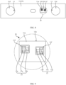
- the connecting member 15 includes a conductive elastic piece 15d disposed in the mounting region 11a, a plug-in hole 11g extending along the thickness direction Y of the housing 10 in the mounting region 11a is formed in the mounting region 11a, the plug-in protrusion 12b is plug-fitted with the plug-in hole 11g, the conductive elastic piece 15d is disposed on a side wall of the plug-in hole 11g and abuts against the plug-in protrusion 12b under the elastic force of the conductive elastic piece 15d, and the conductor 13 is electrically connected to the plug-in protrusion 12b through the conductive elastic piece 15d.
- the conductive elastic piece 15d may be a conductive metal elastic piece, or may be a non-metallic elastic piece with a conductive coating on a surface, specifically, it may be an elastic sheet structure.
- the shape of the plug-in hole 11g can be specifically set according to the shape of the plug-in protrusion 12b, for example, may be square, circle, or oval, and is not specifically limited herein.
- the plug-in hole 11g can be a through hole extending along the thickness direction Y of the housing 10 in the mounting region 11a, or may be a non-through hole, and is not specifically limited herein.
- the number of conductive elastic pieces 15d in the plug-in hole 11g may be one or more.
- the plug-in hole 11g includes a first plug-in hole 11g and a second plug-in hole 11g, where the second plug-in hole 11g is formed at the bottom of the first plug-in hole 11g, the conductive elastic piece 15d is disposed on a side wall of the second plug-in hole 11g, a boss is formed at a position where the plug-in protrusion 12b is connected to the sampling module 12, the first plug-in hole 11g can accommodate the boss, and after the plug-in protrusion 12b is plugged in the second plug-in hole 11g and the plug-in protrusion 12b abuts against the conductive elastic piece 15d, the boss is located in the first plug-in hole 11g, which avoids structural interference between the sampling module 12 and the plug-in hole 11g, so that an outer surface of the sampling module 12 does not protrude from the outer surface of the housing 10, so as to improve the space utilization of the battery cell 110.
- the plug-in hole 11g may alternatively be a straight hole (the cross-section of the axis of the through hole has no step), the surface of the sampling module 12 facing the mounting region 11a is flat, and the plug-in protrusion 12b of the sampling module can be directly plug-fitted with the plug-in hole 11g.
- the plug-in protrusion 12b is plug-fitted with the plug-in hole 11g, and under the elastic force of the conductive elastic piece 15d, the plug-in protrusion 12b always maintains electrical connection with the conductive elastic piece 15d, which has good electrical contact, so as to improve the reliability of signal collection by the sampling module 12.
- the battery cell 110 further includes a fastener 50
- the sampling module 12 is provided with a through hole extending along the thickness direction of the housing 10, and the fastener 50 passes through the through hole to be connected to the mounting region 11a of the housing 10.
- the fastener 50 may be a screw, may be a combination of a screw and a nut, or may be a combination of a screw, a nut, and a gasket.
- the mounting region 11a is provided with a threaded hole, and the fastener 50 passes through the through hole and is threadedly connected to the threaded hole of the mounting region 11a.
- the threaded hole may be replaced with a through hole, and the fixed connection between the sampling module and the housing 10 can be achieved through the connection of a nut and a screw.
- the sampling module 12 and the housing 10 can be disassembled and assembled through the fastener 50, which provides a simple structure and makes assembly and disassembly convenient.
- the electrode terminals 40, the plug-in protrusions 12b, the conductors 13, and the plug-in holes 11g are all provided in two, where the two plug-in protrusions 12b and the two plug-in holes 11g are both spaced apart along the preset direction X, the preset direction X is perpendicular to the thickness direction of the housing 10 in the mounting region 11a, one electrode terminal 40 is electrically connected to one conductive elastic piece 15d through one conductor 13, one conductive elastic piece 15d is electrically connected to one plug-in protrusion 12b, the other electrode terminal 40 is electrically connected to the other conductive elastic piece 15d through the other conductor 13, and the other conductive elastic piece 15d is electrically connected to the other plug-in protrusion 12b.
- one of the two electrode terminals 40 may be a positive electrode terminal and the other may be a negative electrode terminal, and the two are electrically connected to the conductive elastic pieces 15d in the two plug-in holes 11g in one-to-one correspondence through different conductors 13, and the conductive elastic pieces 15d in the two plug-in holes 11g are electrically connected to the two plug-in protrusions 12b in one-to-one correspondence.
- the electrical connection between the two electrode terminals 40 of the battery cell 110 and the two plug-in protrusions 12b of the sampling module 12 can be achieved, and the reliability of the electrical connection between the electrode terminals 40 and the sampling module 12 can be improved through the arrangement of the conductive elastic pieces 15d.
- the number of conductive elastic pieces 15d in the plug-in hole 11g is two, and the two conductive elastic pieces 15d are located on opposite sides of the plug-in protrusion 12b.
- the two conductive elastic pieces 15d in the plug-in hole 11g may be directly opposite or may be diagonally opposite, and are not specifically limited herein.
- the two conductive elastic pieces 15d located on opposite sides of the plug-in protrusion 12b can clamp the plug-in protrusion 12b under the elastic force of the conductive elastic pieces 15d, which further improves the reliability of the electrical connection between the conductive elastic pieces 15d and the plug-in protrusion 12b.
- the housing 10 is provided with a mounting groove 11b.
- the mounting region 11a is a bottom wall of the mounting groove 11b.
- the mounting groove 11b refers to a structure recessed in the thickness direction of the housing 10 on the surface of the housing 10, and its recessed depth may be determined depending on a thickness of the sampling module 12. Moreover, the shape of the mounting groove 11b may be designed in many ways. For example, the mounting groove 11b may be designed in a square, round, oval, pentagonal shape.
- the mounting region 11a can be provided with a groove 11c.
- the mounting region 11a is constructed as the bottom wall of the mounting groove 11b, so that the mounting region 11a has a certain height difference from the surface of the housing 10, which makes the mounting of the sampling module 12 more stable, and also avoids the sampling module 12 protruding from the surface of the housing 10, leading to the ineffective utilization of the space in a height direction of the battery cell 110.
- the housing 10 includes a shell 20 and an end cover 11 covering the shell 20, where the sampling module 12, the electrode terminal 40, and the conductor 13 are all connected to the end cover 11.
- the shell 20 refers to a structure that can accommodate the electrode assembly 30.
- the end cover 11 refers to a component that covers the shell 20, so that the shell 20 has a closed cavity inside.
- the sampling module 12 and the conductor 13 are both arranged on the end cover 11, so that the conductor 13 is more easily electrically connected to the electrode terminal 40 on the end cover 11, which shortens the transmission path of the electrical signal, and helps to improve the reliability of signal collection by the sampling module 12.
- the end cover 11 is provided with a through hole 11d extending along a thickness direction of the end cover 11.
- the through hole 11d is configured for the mounting of the electrode terminal 40, and one end of the conductor 13 disposed on the end cover 11 extends into the through hole 11d.
- One end of the conductor 13 extends into the through hole 11d for the purpose that when the electrode terminal 40 is mounted in the through hole 11d, one end of the conductor 13 is in contact with the electrode terminal 40, so as to achieve electrical communication between the conductor 13 and the electrode terminal 40.
- the amount of extension of the conductor 13 into the through hole 11d it should not be too little, nor too much. Too much will occupy too much space in the through hole 11d, resulting in the electrode terminal 40 unable to be mounted in the through hole 11d.
- One end of the conductor 13 extends into the through hole 11d, which makes the electrical connection between the electrode terminal 40 and the conductor 13 more convenient, and helps to improve the assembly efficiency of the battery cell 110.
- the conductor 13 is embedded in the end cover 11, and one end of the conductor 13 extends in and passes through a wall of the through hole 11d.
- the conductor 13 is embedded in the end cover 11, which can be understood as follows: Most of the structure of the conductor 13 is embedded in the end cover 11.
- the conductor 13 is embedded in the end cover 11 in many ways, for example, by injection molding the conductor 13 into the end cover 11; or by opening a hole in the end cover 11 and threading the conductor 13 through the hole.
- the material of the end cover 11 is an insulating material, or example, rubber or plastic, the conductor 13 embedded in the end cover 11 does not need to be insulated with an insulating sheath.
- the part of the conductor 13 that extends through the wall of the through hole 11d may be, but is not limited to, a nickel sheet, which is welded to the electrode terminal 40 in the through hole 11d during connection.
- the conductor 13 is embedded in the end cover 11, so that the conductor 13 is avoided from being directly exposed on the surface of the end cover 11, which easily causes structural interference inside the battery cell 110; and moreover, the insulation of the outer surface of the conductor 13 can also be implemented by embedding the conductor 13 in the end cover 11.
- the numbers of through holes 11d and conductors 13 are both two, the two conductors 13 are disposed on the end cover 11, and one ends of the two conductors 13 respectively extend into the two through holes 11d.
- each conductor 13 The extension of one end of each conductor 13 into the corresponding through hole 11d means that the signals collected by the sampling module 12 are transmitted by the two electrode terminals 40, greatly improving the reliability of signal collection. Moreover, the two conductors 13 are both disposed on the end cover 11 and are respectively connected to the two electrode terminals 40, which makes the signal collection circuit layout of the battery cell 110 more concise and reasonable.
- the conductors 13 When the two conductors 13 are disposed on the end cover 11, the conductors 13 may be directly arranged on the surface of the end cover 11, or may be arranged inside the end cover 11.
- One ends of the conductors 13 extend into the corresponding through holes 11d respectively, so that the conductors 13 can be electrically connected to the electrode terminals 40 and transmit status signals through the electrode terminals 40, which further improves the reliability of signal collection.
- this application provides a battery 100, including the foregoing battery cell 110.
- this application provides an electric apparatus, including the foregoing battery 100, where the battery 100 is configured to provide electric energy.
- this application provides an intelligent cell sampling structure-gold finger solution, where a conductor 13 and a connecting member 15 are injection molded on an end cover 11, and a sampling module 12 is provided with a corresponding conductive portion 12a.
- Two conductors 13 are respectively connected to corresponding electrode terminals 40, electrical signals are transmitted to the connecting member 15 (for example, an elastic piece) through the conductors 13, and then voltage sampling is implemented through contact between the connecting member 15 and the conductive portion 12a.
- the mounting method of the sampling module 12 on the end cover 11 may be a snap-fit and direct plugging method.
- the snap-fit method is that: the sampling module 12 is plugged in the end cover 11 along the preset direction X, the sampling module 12 is fixed using second limiting pieces 14b on two sides, and after the sampling module 12 is plugged in place, the first limiting piece 14a (such as an elastic piece snap-fit) at the tail end is uplifted to fix the sampling module 12.
- the direct plugging method is that: the conductive portion 12a is designed as a plug-in protrusion 12b, and the plug-in protrusion 12b is directly plugged into the connecting member 15.
Landscapes
- Chemical & Material Sciences (AREA)
- Chemical Kinetics & Catalysis (AREA)
- Electrochemistry (AREA)
- General Chemical & Material Sciences (AREA)
- Engineering & Computer Science (AREA)
- Microelectronics & Electronic Packaging (AREA)
- Manufacturing & Machinery (AREA)
- Physics & Mathematics (AREA)
- General Physics & Mathematics (AREA)
- Connection Of Batteries Or Terminals (AREA)
- Battery Mounting, Suspending (AREA)
Applications Claiming Priority (2)
| Application Number | Priority Date | Filing Date | Title |
|---|---|---|---|
| CN202222499524.2U CN217934153U (zh) | 2022-09-21 | 2022-09-21 | 电池单体、电池及用电装置 |
| PCT/CN2023/080550 WO2024060522A1 (fr) | 2022-09-21 | 2023-03-09 | Élément de batterie, batterie et appareil électrique |
Publications (2)
| Publication Number | Publication Date |
|---|---|
| EP4503261A1 true EP4503261A1 (fr) | 2025-02-05 |
| EP4503261A4 EP4503261A4 (fr) | 2026-04-15 |
Family
ID=84174314
Family Applications (1)
| Application Number | Title | Priority Date | Filing Date |
|---|---|---|---|
| EP23866825.5A Pending EP4503261A4 (fr) | 2022-09-21 | 2023-03-09 | Élément de batterie, batterie et appareil électrique |
Country Status (4)
| Country | Link |
|---|---|
| US (1) | US20250070426A1 (fr) |
| EP (1) | EP4503261A4 (fr) |
| CN (1) | CN217934153U (fr) |
| WO (1) | WO2024060522A1 (fr) |
Families Citing this family (2)
| Publication number | Priority date | Publication date | Assignee | Title |
|---|---|---|---|---|
| CN217934153U (zh) * | 2022-09-21 | 2022-11-29 | 宁德时代新能源科技股份有限公司 | 电池单体、电池及用电装置 |
| CN221508279U (zh) * | 2024-05-15 | 2024-08-09 | 宁德时代新能源科技股份有限公司 | 一种电池系统和用电装置 |
Family Cites Families (7)
| Publication number | Priority date | Publication date | Assignee | Title |
|---|---|---|---|---|
| US5159272A (en) * | 1988-07-27 | 1992-10-27 | Gnb Incorporated | Monitoring device for electric storage battery and configuration therefor |
| JP2008078083A (ja) * | 2006-09-25 | 2008-04-03 | Shin Kobe Electric Mach Co Ltd | 電池状態検知装置 |
| JP5230762B2 (ja) * | 2011-02-25 | 2013-07-10 | 三菱重工業株式会社 | 計測端子装置 |
| CN206422105U (zh) * | 2017-01-23 | 2017-08-18 | 浙江天地人科技有限公司 | 一种铅酸蓄电池中盖 |
| CN113363682B (zh) * | 2021-08-06 | 2021-11-02 | 江苏时代新能源科技有限公司 | 电池、用电装置、电池的制造方法以及制造设备 |
| CN217934153U (zh) * | 2022-09-21 | 2022-11-29 | 宁德时代新能源科技股份有限公司 | 电池单体、电池及用电装置 |
| CN218919083U (zh) * | 2022-09-29 | 2023-04-25 | 宁德时代新能源科技股份有限公司 | 电池单体的端盖组件、电池单体、电池以及用电装置 |
-
2022
- 2022-09-21 CN CN202222499524.2U patent/CN217934153U/zh active Active
-
2023
- 2023-03-09 WO PCT/CN2023/080550 patent/WO2024060522A1/fr not_active Ceased
- 2023-03-09 EP EP23866825.5A patent/EP4503261A4/fr active Pending
-
2024
- 2024-11-14 US US18/947,118 patent/US20250070426A1/en active Pending
Also Published As
| Publication number | Publication date |
|---|---|
| US20250070426A1 (en) | 2025-02-27 |
| WO2024060522A1 (fr) | 2024-03-28 |
| EP4503261A4 (fr) | 2026-04-15 |
| CN217934153U (zh) | 2022-11-29 |
Similar Documents
| Publication | Publication Date | Title |
|---|---|---|
| US20250070426A1 (en) | Battery cell, battery, and electric apparatus | |
| CN216903165U (zh) | 柔性电路板组件、电池及用电装置 | |
| JP7534533B2 (ja) | 電池及び電力消費装置 | |
| CN222355563U (zh) | 连接器、电池以及用电装置 | |
| CN217768550U (zh) | 电池单体的端盖组件、电池单体、电池以及用电设备 | |
| CN216850249U (zh) | 电池及用电装置 | |
| EP3896794B1 (fr) | Connecteur | |
| CN211629204U (zh) | 电池组及装置 | |
| CN221427820U (zh) | 电池采样装置、电池及用电装置 | |
| EP4421963B1 (fr) | Bloc-batterie à densité énergétique améliorée par amélioration de la liaison d'un fil de détection de barre omnibus | |
| CN221407581U (zh) | 采集组件、电池及用电装置 | |
| CN217740741U (zh) | 电池单体、电池及用电设备 | |
| CN216015615U (zh) | 转接部件、电池单体、电池、用电装置以及电池单体的制造设备 | |
| CN221353093U (zh) | 电池连接组件、电池及用电装置 | |
| WO2023123001A1 (fr) | Batterie, dispositif électrique et procédé d'assemblage de batterie | |
| CN223843124U (zh) | 电池装置及用电装置 | |
| CN221407567U (zh) | 电池输出极连接件、电池及用电装置 | |
| CN223956752U (zh) | 电池装置及用电装置 | |
| CN222463335U (zh) | 电池及用电设备 | |
| CN217768682U (zh) | 采样组件、电池及用电装置 | |
| EP4668499A1 (fr) | Appareil de distribution d'énergie, batterie et dispositif électrique | |
| CN219696525U (zh) | 采样组件、电池以及用电装置 | |
| CN222914877U (zh) | 电池装置及用电装置 | |
| CN223039093U (zh) | 电池单体、电池装置及用电设备 | |
| CN222705754U (zh) | 电池装置、用电装置和连接器结构 |
Legal Events
| Date | Code | Title | Description |
|---|---|---|---|
| STAA | Information on the status of an ep patent application or granted ep patent |
Free format text: STATUS: THE INTERNATIONAL PUBLICATION HAS BEEN MADE |
|
| PUAI | Public reference made under article 153(3) epc to a published international application that has entered the european phase |
Free format text: ORIGINAL CODE: 0009012 |
|
| STAA | Information on the status of an ep patent application or granted ep patent |
Free format text: STATUS: REQUEST FOR EXAMINATION WAS MADE |
|
| 17P | Request for examination filed |
Effective date: 20241024 |
|
| AK | Designated contracting states |
Kind code of ref document: A1 Designated state(s): AL AT BE BG CH CY CZ DE DK EE ES FI FR GB GR HR HU IE IS IT LI LT LU LV MC ME MK MT NL NO PL PT RO RS SE SI SK SM TR |
|
| RAP1 | Party data changed (applicant data changed or rights of an application transferred) |
Owner name: CONTEMPORARY AMPEREX TECHNOLOGY(HONG KONG) LIMITED |
|
| DAV | Request for validation of the european patent (deleted) | ||
| DAX | Request for extension of the european patent (deleted) | ||
| REG | Reference to a national code |
Ref country code: DE Ref legal event code: R079 Free format text: PREVIOUS MAIN CLASS: H01M0010480000 Ipc: H01M0010420000 |
|
| A4 | Supplementary search report drawn up and despatched |
Effective date: 20260312 |
|
| RIC1 | Information provided on ipc code assigned before grant |
Ipc: H01M 10/42 20060101AFI20260306BHEP Ipc: H01M 50/569 20210101ALI20260306BHEP Ipc: G01R 31/3835 20190101ALI20260306BHEP Ipc: H01M 50/147 20210101ALI20260306BHEP Ipc: H01M 50/172 20210101ALI20260306BHEP Ipc: H01M 50/55 20210101ALI20260306BHEP Ipc: G01R 31/364 20190101ALN20260306BHEP |