EP4503343A1 - Verbindergehäuse mit stiftbefestigungsstruktur - Google Patents
Verbindergehäuse mit stiftbefestigungsstruktur Download PDFInfo
- Publication number
- EP4503343A1 EP4503343A1 EP23777844.4A EP23777844A EP4503343A1 EP 4503343 A1 EP4503343 A1 EP 4503343A1 EP 23777844 A EP23777844 A EP 23777844A EP 4503343 A1 EP4503343 A1 EP 4503343A1
- Authority
- EP
- European Patent Office
- Prior art keywords
- connector housing
- terminal
- pin terminal
- pin
- rigid
- Prior art date
- Legal status (The legal status is an assumption and is not a legal conclusion. Google has not performed a legal analysis and makes no representation as to the accuracy of the status listed.)
- Pending
Links
Images


Classifications
-
- H—ELECTRICITY
- H01—ELECTRIC ELEMENTS
- H01R—ELECTRICALLY-CONDUCTIVE CONNECTIONS; STRUCTURAL ASSOCIATIONS OF A PLURALITY OF MUTUALLY-INSULATED ELECTRICAL CONNECTING ELEMENTS; COUPLING DEVICES; CURRENT COLLECTORS
- H01R13/00—Details of coupling devices of the kinds covered by groups H01R12/70 or H01R24/00 - H01R33/00
- H01R13/40—Securing contact members in or to a base or case; Insulating of contact members
- H01R13/42—Securing in a demountable manner
- H01R13/422—Securing in resilient one-piece base or case, e.g. by friction; One-piece base or case formed with resilient locking means
- H01R13/4223—Securing in resilient one-piece base or case, e.g. by friction; One-piece base or case formed with resilient locking means comprising integral flexible contact retaining fingers
- H01R13/4226—Securing in resilient one-piece base or case, e.g. by friction; One-piece base or case formed with resilient locking means comprising integral flexible contact retaining fingers comprising two or more integral flexible retaining fingers acting on a single contact
-
- H—ELECTRICITY
- H01—ELECTRIC ELEMENTS
- H01R—ELECTRICALLY-CONDUCTIVE CONNECTIONS; STRUCTURAL ASSOCIATIONS OF A PLURALITY OF MUTUALLY-INSULATED ELECTRICAL CONNECTING ELEMENTS; COUPLING DEVICES; CURRENT COLLECTORS
- H01R13/00—Details of coupling devices of the kinds covered by groups H01R12/70 or H01R24/00 - H01R33/00
- H01R13/02—Contact members
-
- H—ELECTRICITY
- H01—ELECTRIC ELEMENTS
- H01R—ELECTRICALLY-CONDUCTIVE CONNECTIONS; STRUCTURAL ASSOCIATIONS OF A PLURALITY OF MUTUALLY-INSULATED ELECTRICAL CONNECTING ELEMENTS; COUPLING DEVICES; CURRENT COLLECTORS
- H01R13/00—Details of coupling devices of the kinds covered by groups H01R12/70 or H01R24/00 - H01R33/00
- H01R13/73—Means for mounting coupling parts to apparatus or structures, e.g. to a wall
- H01R13/74—Means for mounting coupling parts in openings of a panel
- H01R13/748—Means for mounting coupling parts in openings of a panel using one or more screws
-
- H—ELECTRICITY
- H01—ELECTRIC ELEMENTS
- H01R—ELECTRICALLY-CONDUCTIVE CONNECTIONS; STRUCTURAL ASSOCIATIONS OF A PLURALITY OF MUTUALLY-INSULATED ELECTRICAL CONNECTING ELEMENTS; COUPLING DEVICES; CURRENT COLLECTORS
- H01R2101/00—One pole
Definitions
- the present invention relates to the field of electrical connection technology, and more specifically, to a connector housing with an improved pin fixing structure.
- Electric connectors are widely used in various industrial fields, such as vehicle connectors in automotive electronic and electrical architecture, as well as energy storage connectors in photovoltaic power generation systems.
- Electric connectors typically include a plastic outer housing and a terminal installed inside the housing. After the terminal is inserted into the housing, its front and rear ends are electrically connected to other conductors through appropriate wiring techniques (for example, the front end of the terminal is plugged into a mating terminal, and the rear end of the terminal is connected to a wire by means of crimping or bolting).
- Figure 1A shows a post-wiring state of a socket connector used to accommodate a pin terminal, where the pin terminal 110 is used to be inserted into a plastic housing of the socket connector 100 from the rear end of the connector, and then the front end of the socket connector 100 can be plugged together with a mating connector (not shown).
- Figure 1B shows the socket connector in Figure 1A from another perspective.
- Figure 2 shows a type of pin terminal 110 that can be used in the application shown in Figure 1A .
- the pin terminal 110 includes a front end 112 to be inserted into the socket connector 100, and a tail end 116 to be left outside the socket connector 100.
- the tail end 116 may be flat and provided with a threaded hole 118, which can be used to connect copper busbars or other conductors with threaded holes to the tail end of the pin terminal 110 through fastening elements such as bolts 120.
- the front end 112 of the pin terminal 110 can be divided into three sections, namely positioning boss 113, snap mounting section 114, and plug head section 115.
- the positioning boss 113 is used to mate with the housing structure of the socket connector 100 to provide a basic positioning.
- the snap mounting section 114 may be provided with an annular snap slot 1141 for mating with elastic latches described below in conjunction with Figure 1C .
- the cylindrical plug head section 115 is located at the end and is used to establish an electrical connection with a mating terminal in a mating connector.
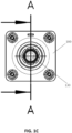
- Figure 1C shows a view of the front end (i.e. the end opposite to the insertion end of the pin terminal) of this socket connector 100.
- the elastic latches 130 are a cantilever structure extending from an inner wall of the cavity of the socket connector 100.
- This cantilever generally extends axially, and its free end includes a snap protrusion 135 protruding radially inwardly.
- the snap protrusion 135 is used to snap into the snap slot structure 1141 on the pin terminal, thereby fixing the pin terminal 110.
- the section where a physical connection occurs between the pin terminal 110 and the cavity of the socket connector 100 is divided into a rigid mating section 151 and an elastic mating section 152.
- the rigid mating section is defined by a depth of a terminal rear insertion hole at the tail end of socket connector 100, and the body of pin terminal 110 is in close contact with the inner wall of the terminal rear insertion hole throughout the entire thickness range.
- the elastic mating section 152 is the section where the body of the pin terminal 110 and the elastic latches 130 come into contact, and this section may be substantially defined by an axial extension length of the elastic latches 130.
- the length of the rigid mating section 151 plus the length of the elastic mating section 152 is the total mating length between the pin terminal and the connector housing. For example, if the length of the rigid mating section is 7.8 mm and the length of the elastic mating section is 6.3 mm, the total mating length is 14.1 mm.
- a bolt 120 shown in Figure 1A is to be rotated by a torque tool to achieve wiring operations.
- the transmission of force applied by the tool may cause the pin terminal 110 to shake inside the housing, and the elastic latches 130 will deform with the shaking of the pin. After the deformation of the elastic latches 130, the interference between the latches and the pin will be reduced, thereby increasing the risk of pin detachment.
- the significant shaking of the pin terminal 110 during installation will affect the accuracy of the torque loaded, thereby affecting the reliability of the electrical connection.
- a connector housing defines a terminal channel for receiving a pin terminal and comprises a pin fixing structure for the pin terminal, wherein the pin fixing structure comprises: several flexible positioning elements distributed along the circumference of the terminal channel, wherein the flexible positioning elements are to be used for elastically snapping into the pin terminal; and several rigid positioning elements distributed along the circumference of the terminal channel, wherein the rigid positioning elements are to abut against the pin terminal within a first predetermined length along an axial direction of the terminal channel, so as to limit the swinging of the pin terminal.
- the length of the flexible positioning element in the axial direction of the terminal channel, the length of the flexible positioning element at least partially overlaps with the first predetermined length.
- the several flexible positioning elements are several elastic latches extending along the axial direction of the terminal channel, which are to be used for snapping into a snap slot structure that is located on the pin terminal for snap-mounting purpose.
- the several rigid positioning elements are several rigid ribs extending along the axial direction of the terminal channel.
- inner walls of the elastic latches and inner walls of the rigid ribs are co-circumferential.
- the terminal channel is provided with an annular step therein, wherein the annular step is to physically interfere with a positioning boss of the pin terminal to define an end of an insertion stroke of the pin terminal.
- the elastic latch is a cantilever structure that extends from the annular step and is provided with a radially inward protruding snap protrusion at its free end, wherein the snap protrusion is to snap into a snap slot structure on a plug terminal.
- the rigid ribs extend from the annular step and are to provide physical contact to the plug terminal at angular positions different from the elastic latches.
- the height of the rigid rib is greater than the height of the elastic latch.
- a curve length of the rigid rib around the axis of the terminal channel is smaller than a curve length of the elastic latch.
- a curve length of the rigid rib around the axis of the terminal channel is greater than a curve length of the elastic latch.
- the number of the rigid ribs and the number of the elastic latches are greater than or equal to three, respectively.
- the several elastic latches are evenly distributed along a circumferential direction, and the several rigid ribs are respectively disposed between adjacent elastic latches.
- the rigid ribs and the elastic latches are staggered one by one.
- a position reached by an axial extension of the rigid rib exceeds a position where the elastic latch is snapping into the pin terminal.
- the connector housing is a socket connector housing.
- a connector assembly which comprises the connector housing described above and a pin terminal, wherein the pin terminal comprises a tail end for wiring and a front end for inserting into the connector housing, wherein the front end comprises a positioning boss, a snap mounting section, and a plug head section, wherein the snap mounting section has an annular snap slot for mating with elastic latches inside the connector housing, wherein when the pin terminal is inserted into the connector housing, the elastic latches inside the connector housing are snapped into the snap slot on the snap mounting section of the front end of the pin terminal to achieve positioning.
- a socket connector housing 300 includes a cavity which is open at two ends for accommodating a pin terminal, such as the pin terminal 110 shown in Figure 2 .
- the pin terminal 110 can be inserted from a tail end of the socket connector housing 300, and its plug head section 115 can pass through a terminal channel 301.
- the terminal channel 301 is provided with an annular step 350 therein, which is used to physically interfere with the positioning boss 113 of the pin terminal to define an end of an insertion stroke of the pin terminal 110.
- elastic latches 330 are distributed along the circumference of the terminal channel 301 and extend inwardly in an axial direction from the annular step 350, for mating with the snap mounting section 114 on the pin terminal 110.
- the rigid ribs 340 also extend inwardly in the axial direction from the annular step 350, for providing physical contact and positioning with a plug terminal.
- the height of the rigid rib 340 is greater than the height of the elastic latch 330.
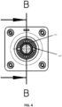
- FIG 4 shows a view of the front end (i.e., the side opposite to the tail end of the inserted pin) of the socket connector housing 300 shown in Figure 3 .
- the distribution of the elastic latches 330 and the rigid ribs 340 along the circumferential direction of the terminal channel 301 can be seen.
- Each elastic latch 330 is spaced 90 degrees apart from an adjacent elastic latch, and each rigid rib 340 is spaced 90 degrees apart from adjacent rigid rib.
- the elastic latch 330 has a cantilever structure that extends generally in an axial direction, and a radially inward protruding snap protrusion 335 is provided at a free end of the elastic latch.
- the snap protrusion 335 is used to snap into the snap slot structure on the pin terminal 110, thereby fixing the pin terminal.
- an inner wall of the elastic latch 330 (excluding the snap protrusion part at its end) and an inner wall of the rigid rib 340 are co-circumferential, that is, their radial distances to the axis of the terminal channel 301 are equal.
- the rigid fitting length is, based on a depth of a terminal rear insertion hole, further extended to the end of the rigid rib 340.
- the design in Figures 3 and 4 increases the rigid fitting length of the pin terminal to 14.9 mm (D2 in Figure 5 ) without changing the design of other fitting parts and the outer contour dimensions of the socket. Due to the fact that the length of the elastic latch 330 partially overlaps with the rigid fitting length D2 in the axial direction of the terminal channel 301, the rigid fitting and flexible fitting are combined and applied to the front end of the pin terminal 110. With this method, the shaking of the pin terminal can be suppressed, which can be reflected as a reduced maximum deflection angle between the pin terminal 110 and the socket connector housing 300 while there is no change to a fitting clearance between the pin terminal and the housing.
- the rigid rib 340 may exceed the elastic latch 330 in height, thus further preventing or suppressing deformation of the elastic latch during installation on the client side, thereby reducing the risk of pin detachment caused by deformation of the elastic latch.
- the details regarding the plug terminal and rigid ribs are only provided as examples.
- rigid rib or "rib” is to be understood that a rib structure is different from a cantilever structure of the elastic latch, such that it does not have physical properties that are prone to elastic deformation like the elastic latch. Therefore, the "rigidity" of the rib should be widely understood as various structural rigidity stronger than the cantilever structure, rather than absolute rigidity.
- the pin terminal 110 as shown in Figure 2 is used, and the socket connector housing 300 with four elastic latches 330 and four rigid ribs 340 as shown in Figure 4 is used.
- the pin terminal is not limited to the structure shown in Figure 2 , but can adopt any terminal with a snap mounting section that matches with the elastic latches.
- the pin fixing structure of the socket connector housing is not limited to four elastic latches and four rigid ribs, but can be any complex number of elastic latches and rigid ribs, such as two elastic latches and two rigid ribs. In some variations, the number of the elastic latches and rigid ribs may not be the same, for example, four elastic latches and two rigid ribs.
- the connector housing is not limited to socket connector housing, but can be any suitable type of connector housing used to accommodate a pin terminal (thus requiring a terminal stability structure).
- the use of elastic latches is only a specific example of the present invention. It can be understood that several elastic latches can be reasonably generalized to be several flexible positioning elements distributed along the circumference of the terminal channel, which are used for elastically snapping into the pin terminal.
- the use of rigid ribs is only a specific example of the present invention. It can be understood that several rigid ribs can be reasonably generalized to be several rigid positioning elements distributed along the circumference of the terminal channel, which are used to abut against the pin terminal within a first predetermined length in the axial direction of the terminal channel.
- the length of the flexible positioning element at least partially overlaps with the first predetermined length, such that the rigid fitting and flexible fitting are combined and applied to the front end of the pin terminal.
Landscapes
- Connector Housings Or Holding Contact Members (AREA)
Applications Claiming Priority (2)
| Application Number | Priority Date | Filing Date | Title |
|---|---|---|---|
| CN202210331387.3A CN114628936B (zh) | 2022-03-30 | 2022-03-30 | 具有插针固定结构的连接器壳体 |
| PCT/CN2023/081565 WO2023185469A1 (zh) | 2022-03-30 | 2023-03-15 | 具有插针固定结构的连接器壳体 |
Publications (2)
| Publication Number | Publication Date |
|---|---|
| EP4503343A1 true EP4503343A1 (de) | 2025-02-05 |
| EP4503343A4 EP4503343A4 (de) | 2026-03-18 |
Family
ID=81903615
Family Applications (1)
| Application Number | Title | Priority Date | Filing Date |
|---|---|---|---|
| EP23777844.4A Pending EP4503343A4 (de) | 2022-03-30 | 2023-03-15 | Verbindergehäuse mit stiftbefestigungsstruktur |
Country Status (3)
| Country | Link |
|---|---|
| EP (1) | EP4503343A4 (de) |
| CN (1) | CN114628936B (de) |
| WO (1) | WO2023185469A1 (de) |
Families Citing this family (1)
| Publication number | Priority date | Publication date | Assignee | Title |
|---|---|---|---|---|
| CN114628936B (zh) * | 2022-03-30 | 2025-01-28 | 菲尼克斯亚太电气(南京)有限公司 | 具有插针固定结构的连接器壳体 |
Family Cites Families (17)
| Publication number | Priority date | Publication date | Assignee | Title |
|---|---|---|---|---|
| JP3646836B2 (ja) * | 1997-03-27 | 2005-05-11 | 住友電装株式会社 | コネクタ |
| JP4093148B2 (ja) * | 2003-09-04 | 2008-06-04 | 住友電装株式会社 | コネクタ |
| EP1873871B1 (de) * | 2006-06-30 | 2011-03-09 | Sumitomo Wiring Systems, Ltd. | Elektrischer Verbinder |
| CN202495608U (zh) * | 2012-03-09 | 2012-10-17 | 苏州瑞可达连接系统有限公司 | 电连接器插针端子定位安装结构 |
| US9071016B2 (en) * | 2013-10-03 | 2015-06-30 | Delphi Technologies, Inc. | Electrical connector with a sliding flexible cantilever beam terminal retainer |
| CN206340736U (zh) * | 2016-11-22 | 2017-07-18 | 常州诺德电子有限公司 | 推拉式插针插座连接器 |
| DE102018124197A1 (de) * | 2018-10-01 | 2020-04-02 | Harting Electric Gmbh & Co. Kg | Kontaktträger mit stabiler Rastvorrichtung |
| CN209029569U (zh) * | 2018-10-24 | 2019-06-25 | 深圳巴斯巴科技发展有限公司 | 一种连接器插孔固定结构 |
| CN209133737U (zh) * | 2018-11-01 | 2019-07-19 | 深圳巴斯巴科技发展有限公司 | 一种结构紧凑便于安装的连接器 |
| CN109742582B (zh) * | 2019-01-25 | 2025-06-10 | 深圳巴斯巴科技发展有限公司 | 一种连接器结构 |
| AT522822B1 (de) * | 2019-08-07 | 2021-12-15 | Neutrik Ag | Elektrischer Steckverbinder |
| CN211719898U (zh) * | 2019-12-31 | 2020-10-20 | 深圳市中车业成实业有限公司 | 一种高速动车用多路以太网矩形连接器 |
| CN212908192U (zh) * | 2020-06-10 | 2021-04-06 | 江西巴斯巴新能源技术有限公司 | 一种连接器 |
| CN213660677U (zh) * | 2020-11-27 | 2021-07-09 | 深圳市沃尔新能源电气科技股份有限公司 | 充电插座和电动汽车 |
| CN112713431B (zh) * | 2021-01-13 | 2022-04-19 | 苏州快可光伏电子股份有限公司 | 高可靠性且电气性能优异的光伏系统连接器 |
| CN215266778U (zh) * | 2021-07-10 | 2021-12-21 | 浙江弗沙朗能源股份有限公司 | 一种带止退插针的光伏连接器 |
| CN114628936B (zh) * | 2022-03-30 | 2025-01-28 | 菲尼克斯亚太电气(南京)有限公司 | 具有插针固定结构的连接器壳体 |
-
2022
- 2022-03-30 CN CN202210331387.3A patent/CN114628936B/zh active Active
-
2023
- 2023-03-15 EP EP23777844.4A patent/EP4503343A4/de active Pending
- 2023-03-15 WO PCT/CN2023/081565 patent/WO2023185469A1/zh not_active Ceased
Also Published As
| Publication number | Publication date |
|---|---|
| CN114628936A (zh) | 2022-06-14 |
| CN114628936B (zh) | 2025-01-28 |
| EP4503343A4 (de) | 2026-03-18 |
| WO2023185469A1 (zh) | 2023-10-05 |
Similar Documents
| Publication | Publication Date | Title |
|---|---|---|
| US4334730A (en) | Insulated from ground bulkhead adapter | |
| US6386888B1 (en) | Modular connector | |
| US6042432A (en) | Terminal for charging with large current | |
| US11177616B2 (en) | Electrical plug with a protective conductor contact and protective conductor connector element formed integrally therewith for grounding exterior parts | |
| US20170271784A1 (en) | Electrical Connection Device, A Method of Manufacturing an Electrical Cable and A Manufactured Electrical Coaxial Cable | |
| CN217062598U (zh) | 具有插针固定环的电连接器 | |
| KR102627300B1 (ko) | 전기 페룰, 전기 연결 장치 및 전기 커넥터 | |
| CN104124556A (zh) | 具有弹性锁闩的电连接器 | |
| US11539155B2 (en) | Contact assembly for a connector housing, connector housing as well as connector assembly and modular connector set with such a connector housing | |
| EP4503343A1 (de) | Verbindergehäuse mit stiftbefestigungsstruktur | |
| CN113363776A (zh) | 鲁棒的,适用于高频的电气端子 | |
| US12237626B2 (en) | Wire harness | |
| EP3800743A1 (de) | Anschlussstück | |
| US20250167482A1 (en) | Electric plug connector and method for installing an electric plug connector | |
| CN217062599U (zh) | 具有插针固定结构的连接器壳体和连接器套件 | |
| US12500366B2 (en) | Electrical plug connector and method for assembling an electrical plug connector | |
| CN222980928U (zh) | 具有二次锁止结构的插座连接器 | |
| CN117996508A (zh) | 连接器、连接器组件及接线盒 | |
| EP4604334A1 (de) | Hermaphroditisches isoliergehäuse, steckverbindersystem und verfahren | |
| EP4668501A1 (de) | Verbinder | |
| CN223986807U (zh) | 一种电机插座及电机 | |
| EP2169779A1 (de) | Elektromagnetische Abschirmung für einen Elektrostecker und Elektrostecker | |
| CN219017951U (zh) | 带有锁紧结构的电连接器 | |
| CN216698950U (zh) | 屏蔽连接件、连接器和连接器组件 | |
| US20250286306A1 (en) | Bent Connector, Intermediate Connector, and Connector Assembly |
Legal Events
| Date | Code | Title | Description |
|---|---|---|---|
| STAA | Information on the status of an ep patent application or granted ep patent |
Free format text: STATUS: THE INTERNATIONAL PUBLICATION HAS BEEN MADE |
|
| PUAI | Public reference made under article 153(3) epc to a published international application that has entered the european phase |
Free format text: ORIGINAL CODE: 0009012 |
|
| STAA | Information on the status of an ep patent application or granted ep patent |
Free format text: STATUS: REQUEST FOR EXAMINATION WAS MADE |
|
| 17P | Request for examination filed |
Effective date: 20241016 |
|
| AK | Designated contracting states |
Kind code of ref document: A1 Designated state(s): AL AT BE BG CH CY CZ DE DK EE ES FI FR GB GR HR HU IE IS IT LI LT LU LV MC ME MK MT NL NO PL PT RO RS SE SI SK SM TR |
|
| DAV | Request for validation of the european patent (deleted) | ||
| DAX | Request for extension of the european patent (deleted) | ||
| A4 | Supplementary search report drawn up and despatched |
Effective date: 20260218 |
|
| RIC1 | Information provided on ipc code assigned before grant |
Ipc: H01R 13/40 20060101AFI20260212BHEP Ipc: H01R 13/02 20060101ALI20260212BHEP Ipc: H01R 13/422 20060101ALI20260212BHEP Ipc: H01R 13/74 20060101ALN20260212BHEP |