EP4503344A2 - Câble électrique confectionné et ensemble connecteur - Google Patents
Câble électrique confectionné et ensemble connecteur Download PDFInfo
- Publication number
- EP4503344A2 EP4503344A2 EP24220897.3A EP24220897A EP4503344A2 EP 4503344 A2 EP4503344 A2 EP 4503344A2 EP 24220897 A EP24220897 A EP 24220897A EP 4503344 A2 EP4503344 A2 EP 4503344A2
- Authority
- EP
- European Patent Office
- Prior art keywords
- contact
- connector
- contact element
- electrical cable
- assembled
- Prior art date
- Legal status (The legal status is an assumption and is not a legal conclusion. Google has not performed a legal analysis and makes no representation as to the accuracy of the status listed.)
- Granted
Links
Images


Classifications
-
- H—ELECTRICITY
- H01—ELECTRIC ELEMENTS
- H01R—ELECTRICALLY-CONDUCTIVE CONNECTIONS; STRUCTURAL ASSOCIATIONS OF A PLURALITY OF MUTUALLY-INSULATED ELECTRICAL CONNECTING ELEMENTS; COUPLING DEVICES; CURRENT COLLECTORS
- H01R13/00—Details of coupling devices of the kinds covered by groups H01R12/70 or H01R24/00 - H01R33/00
- H01R13/02—Contact members
- H01R13/025—Contact members formed by the conductors of a cable end
-
- H—ELECTRICITY
- H01—ELECTRIC ELEMENTS
- H01R—ELECTRICALLY-CONDUCTIVE CONNECTIONS; STRUCTURAL ASSOCIATIONS OF A PLURALITY OF MUTUALLY-INSULATED ELECTRICAL CONNECTING ELEMENTS; COUPLING DEVICES; CURRENT COLLECTORS
- H01R13/00—Details of coupling devices of the kinds covered by groups H01R12/70 or H01R24/00 - H01R33/00
- H01R13/02—Contact members
- H01R13/03—Contact members characterised by the material, e.g. plating, or coating materials
-
- H—ELECTRICITY
- H01—ELECTRIC ELEMENTS
- H01R—ELECTRICALLY-CONDUCTIVE CONNECTIONS; STRUCTURAL ASSOCIATIONS OF A PLURALITY OF MUTUALLY-INSULATED ELECTRICAL CONNECTING ELEMENTS; COUPLING DEVICES; CURRENT COLLECTORS
- H01R13/00—Details of coupling devices of the kinds covered by groups H01R12/70 or H01R24/00 - H01R33/00
- H01R13/40—Securing contact members in or to a base or case; Insulating of contact members
- H01R13/42—Securing in a demountable manner
- H01R13/422—Securing in resilient one-piece base or case, e.g. by friction; One-piece base or case formed with resilient locking means
- H01R13/4223—Securing in resilient one-piece base or case, e.g. by friction; One-piece base or case formed with resilient locking means comprising integral flexible contact retaining fingers
- H01R13/4226—Securing in resilient one-piece base or case, e.g. by friction; One-piece base or case formed with resilient locking means comprising integral flexible contact retaining fingers comprising two or more integral flexible retaining fingers acting on a single contact
-
- H—ELECTRICITY
- H01—ELECTRIC ELEMENTS
- H01R—ELECTRICALLY-CONDUCTIVE CONNECTIONS; STRUCTURAL ASSOCIATIONS OF A PLURALITY OF MUTUALLY-INSULATED ELECTRICAL CONNECTING ELEMENTS; COUPLING DEVICES; CURRENT COLLECTORS
- H01R4/00—Electrically-conductive connections between two or more conductive members in direct contact, i.e. touching one another; Means for effecting or maintaining such contact; Electrically-conductive connections having two or more spaced connecting locations for conductors and using contact members penetrating insulation
- H01R4/02—Soldered or welded connections
- H01R4/029—Welded connections
-
- H—ELECTRICITY
- H01—ELECTRIC ELEMENTS
- H01R—ELECTRICALLY-CONDUCTIVE CONNECTIONS; STRUCTURAL ASSOCIATIONS OF A PLURALITY OF MUTUALLY-INSULATED ELECTRICAL CONNECTING ELEMENTS; COUPLING DEVICES; CURRENT COLLECTORS
- H01R43/00—Apparatus or processes specially adapted for manufacturing, assembling, maintaining, or repairing of line connectors or current collectors or for joining electric conductors
- H01R43/02—Apparatus or processes specially adapted for manufacturing, assembling, maintaining, or repairing of line connectors or current collectors or for joining electric conductors for soldered or welded connections
- H01R43/0207—Ultrasonic-, H.F.-, cold- or impact welding
-
- H—ELECTRICITY
- H01—ELECTRIC ELEMENTS
- H01R—ELECTRICALLY-CONDUCTIVE CONNECTIONS; STRUCTURAL ASSOCIATIONS OF A PLURALITY OF MUTUALLY-INSULATED ELECTRICAL CONNECTING ELEMENTS; COUPLING DEVICES; CURRENT COLLECTORS
- H01R43/00—Apparatus or processes specially adapted for manufacturing, assembling, maintaining, or repairing of line connectors or current collectors or for joining electric conductors
- H01R43/02—Apparatus or processes specially adapted for manufacturing, assembling, maintaining, or repairing of line connectors or current collectors or for joining electric conductors for soldered or welded connections
- H01R43/0214—Resistance welding
Definitions
- the invention relates to a prefabricated electrical cable for an electrical connector, comprising an electrical conductor which is designed as a stranded wire made up of several individual wires, according to the preamble of claim 1.
- the invention also relates to a connector arrangement comprising a prefabricated electrical cable and an electrical connector.
- cables When cables are assembled, their ends, especially the ends of their inner conductors, are prepared for installation in an electrical connector. During this process, the electrical conductors are often cut to a defined length, stripped and provided with one or more contact elements.
- a contact element of the subsequent connector can be electrically and mechanically connected to an electrical conductor guided within a cable sheath and later mounted in a connector housing of the connector. The fully assembled contact element can then be used within the connector to contact a mating contact element of a mating connector.
- Various electrical connectors are known from electrical engineering. Electrical connectors are known to be used to transmit electrical supply signals and/or data signals to the corresponding mating connectors.
- a connector or mating connector can be a plug, a built-in connector, a socket, a coupling or an adapter.
- the term "connector” or “mating connector” used in the context of the invention represents all variants.
- connectors and electrical cables for the automotive industry and for vehicles are subject to high demands on their robustness and the safety of the connectors.
- Electromobility in particular poses major challenges for the automotive industry and its suppliers, as vehicles are High electrical power must be transmitted via cables or plug connections. The thermal load or the resulting waste heat associated with the high current flow is considerable.
- the contact resistance between the electrical conductor of the cable and the contact element as well as between the contact element of the plug connector and the mating contact element of the mating connector should be as low as possible.
- High-voltage connectors are used in the automotive sector, especially in electric and/or hybrid vehicles, to supply a vehicle battery with charging current, to extract the stored energy from the battery and supply it to an electrical consumer, or to connect several batteries or battery modules to each other.
- a high-voltage connector In addition to safe and preferably low-resistance electrical connections within the connector and at the transition to the mating connector, a high-voltage connector must also be easy and cost-effective to manufacture due to the mass suitability of the connector.
- the connector especially a high-voltage connector or a connector for transmitting safety-relevant control signals, should be mechanically robust and reliably secured against unintentional opening.
- the contact between a high-voltage cable and a high-voltage connector is typically made via a contact blade, which is mechanically connected to the electrical conductor of the electrical cable.
- attaching the contact blade to the electrical conductor is comparatively complex and costly.
- the resulting contact resistance is often not ideal.
- a welded contact blade As an alternative to a welded contact blade, it is also known to contact an electrical conductor formed as a stranded wire made of several individual wires in a contact area in a plate-shaped manner for contacting a mating contact element of a mating connector.
- the electrical conductor can thus itself serve as a contact element.
- the compaction of the stranded wire is relatively susceptible to tolerances and therefore usually leads to a more or less uneven contact surface, which can impair the electrical and mechanical connection with the mating contact element of the mating connector.
- the object of the present invention is to provide a prefabricated electrical cable which is preferably suitable for transmitting high electrical currents with low contact resistance and which is particularly suitable for mass production but can nevertheless be produced with high precision.
- a prefabricated electrical cable is provided for an electrical connector.
- the prefabricated electrical cable has an electrical conductor which is designed as a stranded wire made up of several individual wires and which has at least one plate-shaped compacted end section.
- the thickness of the plate-shaped compacted end section can be much smaller than the width and length of the plate-shaped compacted end section.
- the electrical cable can in particular be a high-voltage cable or a high-voltage line for vehicle technology for transmitting high currents, for example with voltages of 1,500 volts or more.
- the prefabricated electrical cable according to the invention can be used particularly advantageously in electrically powered vehicles, for example in electric vehicles or hybrid vehicles.
- the prefabricated electrical cable can have a cable sheath that envelops the electrical conductor.
- the electrical conductor can be exposed (stripped) from the cable sheath in the area of its end section.
- the prefabricated cable can have any number of electrical conductors, for example one inner conductor, two inner conductors or more inner conductors, three inner conductors or more inner conductors, four inner conductors or more inner conductors, five inner conductors or more inner conductors.
- an outer conductor can also be provided.
- the invention is described below essentially using a prefabricated electrical cable that has exactly one inner conductor. However, this is not to be understood as limiting.
- the inner conductor(s) can be arranged coaxially to the central axis of the cable.
- the inner conductor(s) can also be arranged evenly distributed around the central axis of the cable.
- the prefabricated electrical cable has exactly one inner conductor that runs inside the cable sheath.
- Shielding can optionally be provided, for example a cable shield braid spaced from the inner conductor by means of a dielectric material and/or a cable foil.
- the prefabricated electrical cable has an elongated contact element (the length of the contact element can therefore be greater than the width along a longitudinal axis), with at least one side surface which forms a first connection surface which is connected to the compacted end section of the electrical conductor, and with at least one further side surface facing away from the first connection surface which forms a first contact surface for contacting a mating contact surface of a mating contact element of a mating connector.
- the contact element can be manufactured with high precision, for example with a precisely defined size and geometry of the contact surface, which can have a significantly better surface quality compared to the corresponding side surface of the plate-shaped compacted end section. Furthermore, the contact element can remove protruding individual wires that have not been sufficiently compacted.
- the combination of a compacted end section of a stranded wire with a contact element attached thereto combines the advantages of the high current transferability associated with the compaction of the stranded wire with the advantages of a contact surface that can be produced particularly precisely by means of a separate contact element.
- connection between the contact area and the electrical conductor can be robust and low-resistance and therefore suitable for transmitting particularly high currents.
- the use of a contact plate can represent a particularly economical solution.
- the plate-shaped compaction of the electrical conductor on the one hand and the use of a contact plate on the other hand enable maximum material savings while at the same time ensuring extremely precise manufacturing and sufficient dimensional stability.
- any contact element can be designed. However, it is particularly preferred that the contact element is not designed as a contact sleeve.
- the contact element in particular the contact sheet, can be made in one piece, for example as a stamped and bent part.
- the contact sheet can also be deep-drawn or manufactured in some other way.
- the contact sheet is manufactured as a stamped and bent part.
- the contact element and the individual wires of the electrical conductor are made of the same material.
- the contact element can have a coating.
- a silver coating is provided.
- the contact element can preferably be coated by means of strip electroplating.
- the contact resistance can be further improved by a coating. If the contact element is made of aluminum, for example, this can sometimes tend to oxidize in the area of the contact surface. This can be avoided by a coating, for example a silver coating.
- the contact surface is preferably a planar, flat surface.
- the first contact surface can also be curved or round.
- a curved first contact surface can be particularly suitable for contacting the contact lamellae mentioned below or for forming the contact lamellae.
- further side surfaces of the contact element form respective further connection surfaces, wherein the contact element preferably has a total of two to five connection surfaces, which are each connected to the compacted end section of the electrical conductor.
- connection surfaces in addition to the first connection surface, a second connection surface, a third connection surface, a fourth connection surface and/or a fifth connection surface can be provided.
- each of the connection surfaces is provided with another corresponding side surface of the compacted end section.
- the contact element can preferably be folded over an edge of the plate-shaped compacted end portion.
- the contact element can be folded over two edges of the compacted end portion, in particular be U-shaped.
- the contact element can, for example, be folded over three edges of the compacted end section.
- a connecting surface of the contact element is connected to an end face of the plate-shaped compacted end section or is folded over an edge of the end face.
- the contacting options can be increased, for example, additional contact surfaces can be provided for contacting one or more mating contact elements and/or an improved covering of the compacted end section can be provided, for example to cover protruding individual wires.
- the at least one connecting surface is aligned parallel to a corresponding side surface of the compacted end section to which the connecting surface is connected.
- the at least one connecting surface is fully connected to the corresponding side surface of the compacted end section.
- connection surface to the corresponding side surface in particular a full-surface connection, can further reduce the contact resistance and enable the transmission of even higher currents.
- the contact surfaces are each arranged parallel to their corresponding connecting surfaces.
- the at least one connecting surface is materially connected to the compacted end section.
- a material-locking connection between the connection surface and the compacted end section can enable a particularly low transition resistance.
- the compacted end section and the contact element can be connected to one another particularly robustly in this way. Corrosion of the transition area between the contact element and the electrical conductor can also be avoided, especially if the material-locking connection is a gas-tight material-locking connection.
- a screw connection, rivet connection or crimp connection between the electrical conductor and the contact element can preferably be dispensed with within the scope of the invention.
- the electrical conductor can preferably be permanently connected to the contact element, whereby the electrical conductor can no longer be removed from the contact element without causing damage.
- the previously mentioned gas-tight connection can be provided between the connecting surface of the contact element and the corresponding side surface of the plate-shaped compacted end section.
- the at least one connecting surface completely covers a corresponding side surface of the compacted end section to which the connecting surface is connected.
- the contact area for contacting the counter contact area of the counter contact element can be enlarged.
- protruding individual wires can be completely covered.
- a further side surface of the contact element forms a second contact surface for contacting a mating contact surface of a mating contact element of a mating connector.
- further contact surfaces can also be provided, for example a third contact surface, a fourth contact surface and/or a fifth contact surface.
- the use of two contact surfaces, which are arranged on opposite sides of the compacted end section in the case of the connected state of the contact element with the plate-shaped compacted end section, can be advantageous for contacting with the mating connector, for example in order to enable a two-sided, pincer-like contact.
- the at least one contact surface of the contact element is designed as a primarily flat surface for surface contact with the counter contact surface.
- a contact element can be designed in the manner of a contact blade, in combination with the advantages according to the invention.
- the at least one contact surface of the contact element has one or more contact lamellas which are at least partially elastic in the contacting direction for contacting the counter contact surface.
- contact lamellas can increase the contact force to the counter contact element and thus improve the current transfer.
- the contact surface can in principle have any rigid and/or elastic projections on the contact surface (e.g. ribs). In the simplest In this case, however, a surface contact can be provided, i.e. the contact surface can be completely flat or level.
- the contact blades can, for example, be punched out of the contact surface of the contact element.
- the contact blades can also be attached individually or in groups to the contact surface of the contact element.
- the use of a separate contact blade element that is inserted between the contact surface and the mating contact surface and is optionally fixed in the connector, on the assembled cable, in the mating connector or on the mating contact element can also be advantageous.
- At least one of the contact surfaces or that the at least one contact surface each has at least one first latching means for latching with a corresponding second latching means of the connector or connector housing in order to provide mutual latching between the assembled cable and the connector or connector housing when the assembled cable is mounted in the connector or connector housing.
- the locking means can increase the holding force of the assembled prefabricated cable in the connector and advantageously provide a primary and/or secondary locking.
- first locking means and corresponding second locking means can be provided.
- the first locking means is designed as a spring tab punched out of the contact surface.
- the connector in particular the connector housing of the connector, can have a corresponding locking recess or a corresponding locking lug into or behind which the spring tabs can lock in the assembled state of the prefabricated cable.
- the first locking means is designed as a locking lug or locking hook formed on the contact surface
- the connector in particular the connector housing of the connector, can have an elastic spring tab which can snap into place behind the locking lug or behind the locking hook when the assembled cable is in the assembled state.
- the first locking means is designed as a locking recess within the contact surface.
- the connector in particular the connector housing of the connector, can have an elastic spring tab that can lock behind the locking lug or behind the locking hook when the assembled cable is in the assembled state.
- any locking means can be provided which, in combination, enable suitable locking between the assembled electrical cable and the connector or the connector housing.
- the contact element can also have locking elements for locking with the mating contact element and/or mating connector.
- the connector housing can be lockable with a mating connector housing of the mating connector.
- the contact element has further functional elements.
- the at least one contact surface can have at least one coding element, for example a coding element punched out of the contact surface, in order to provide mechanical coding between the contact element and a counter-coding element of the connector or connector housing. In this way, it can be ensured that only a contact element or prefabricated electrical cable approved for connection to the connector can be mounted in the connector or connector housing, and/or that the assembly takes place with correct alignment and positioning.
- the electrical conductor has a conductor cross-section greater than 10 mm 2 , preferably greater than 30 mm 2 , particularly preferably greater than 60 mm 2 , for example greater than 90 mm 2 or even greater than 200 mm 2 .
- a conductor cross-section can be provided which is suitable for electrical energy transmission in high-voltage technology, i.e. for transmitting high electrical currents (for example 100 A to 2 kA) at alternating voltages of 30 V to 1 kV or more or direct voltages of 60 V to 1.5 kV or more, in particular in automotive technology.
- the individual wires of the electrical conductor are welded together in order to form the plate-shaped compacted end section
- the individual wires can be press-welded, resistance-welded or fusion-welded together.
- any material-bonded connection technique is possible.
- the invention also relates to a connector arrangement comprising a prefabricated electrical cable according to the above and following embodiments and the electrical connector.
- the plate-shaped compacted end section can be accommodated within the connector, preferably within a connector housing of the connector.
- the connector housing can in particular be a plastic housing, preferably made of a rigid plastic or hard plastic.
- the connector housing can preferably be manufactured by means of an injection molding process or a deep-drawing process. It can be provided that the connector housing is designed in one piece or preferably in several parts.
- the connector housing can be designed to provide contact protection for the conductive components of the connector.
- the proposed electrical connector is particularly suitable as a high-voltage connector, in particular for use in electromobility.
- the electrical connector can advantageously provide, for example, a cell module connector interface for connecting battery cell modules, with a particularly advantageous design of the contact.
- the prefabricated electrical cable can advantageously be used as a busbar replacement.
- a particularly economical and at the same time high-quality contacting option can be provided.
- the contact element can have a smooth, precisely manufactured contact surface, whereby the contact resistance between the electrical conductor and the contact element can be particularly low due to the compaction of the stranded wire.
- the contact can also be particularly robust and can absorb high cable tensile forces, for example tensile forces greater than 100 N.
- the connector has one or more spring elements which are designed and arranged to generate a contact pressure between at least the first contact surface and the corresponding mating contact surface of the mating contact element when the connector is connected to the mating connector.
- the invention relates to a device for assembling an electrical cable for carrying out the above-mentioned method.
- the values and parameters described here include deviations or fluctuations of ⁇ 10% or less, preferably ⁇ 5% or less, more preferably ⁇ 1% or less, and most preferably ⁇ 0.1% or less of the respective specified value or parameter, provided that these deviations are not excluded in the implementation of the invention in practice.
- the indication of ranges by initial and final values also includes all those values and fractions that are included in the respective specified range, in particular the initial and final values and a respective mean value.
- Figure 1 shows a connector arrangement 1, comprising a prefabricated electrical cable 2 according to the invention and an electrical connector 3.
- the electrical connector 3 has a connector housing 4 in which the prefabricated electrical cable 2 is received with at least one end.
- the cable 2 can preferably be introduced into the connector housing 4 along an assembly direction M.
- connection with a corresponding mating connector 5 is made along a plug-in direction S that runs orthogonally to the mounting direction M, although this is not to be understood as limiting.
- a mating connector housing 6 of the mating connector 5 is shown in Figure 1 shown in dashed lines and also a mating contact element 7 of the mating connector 5 is shown.
- the invention is particularly suitable for use in high-voltage technology in vehicles, for example for the electrical connection between individual batteries, battery modules and/or electrical consumers, such as electric motors.
- the prefabricated electrical cable 2 which is only to be understood as an example, extends along a longitudinal axis L and has a single electrical conductor 8, which is guided within a cable sheath 9.
- a cable sheath 9 is not absolutely necessary, however.
- the electrical conductor 8 preferably has a conductor cross-section greater than 10 mm 2 , in particular greater than 30 mm 2 , particularly preferably greater than 60 mm 2 , for example also greater than 90 mm 2 . In principle, however, other conductor cross-sections can also be provided. It can also be provided that the electrical cable 2 has more than one electrical conductor 8.
- the electrical conductor 8 is designed as a stranded wire made of several individual wires and is compacted in a plate-shaped end section 10, see for example also the Figures 2 and 3
- the individual wires of the electrical conductor 8 are preferably welded together, for example press-welded, resistance-welded or fusion-welded.
- the proposed prefabricated electrical cable 2 has an elongated contact element.
- the contact elements are each designed as contact plates 11, preferably with a thickness of between 0.3 mm and 1.0 mm, particularly preferably with a thickness of between 0.4 mm and 0.6 mm.
- any contact element can be provided, for example a plate-shaped contact element.
- the contact element or contact plate 11 and the individual wires of the electrical conductor 8 can be made of the same material, for example aluminum or copper.
- the contact element or contact plate 11 can also have a coating, preferably a silver coating (not shown).
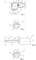
- the Figures 2 and 3 show a first embodiment of the assembled electrical cable 2.
- the contact plate 11 has a side surface which forms a first connection surface 12 which is connected to the compacted end section 10 or to a corresponding side surface of the compacted end section 10 of the electrical conductor 8.
- the contact plate 11 also has a side surface facing away from the first connection surface 12 which forms a first contact surface 13 for Contacting a counter contact surface 14 (see for example Figure 10 ) of the mating contact element 7 of the mating connector 5.
- a particularly low-resistance electrical connection between the electrical conductor 8 and the contact element or contact plate 11 can be provided via the first connection surface 12 on the one hand and a particularly smooth, flat first contact surface 13 for contacting the mating contact element 7 on the other.
- FIG. 4 to 8 some variants of the contact element designed as a contact plate 11 are shown in order to illustrate that further side surfaces of the contact element or contact plate 11 can also form further connection surfaces 15, 17, 18, 19, for example a total of two to five connection surfaces 15, 17, 18, 19, which are each connected to the compacted end section 10 of the electrical conductor 8.
- the contact plate 11 has the first connecting surface 12 and a further, second connecting surface 15, wherein the contact plate 11 is folded over an edge of the plate-shaped compacted end section 10 of the electrical conductor 8.
- This edge can preferably be the edge of the contact plate 11 facing the counter-contact element 7 during the plugging process. In this way, it can be avoided that protruding individual wires have a negative influence on the plugging process.
- a contact surface is formed on the side surface of the contact element or contact plate 11 facing away from the respective connection surface 12, 15, 17, 18, 19.
- the number of contact surfaces does not necessarily have to correspond to the number of connection surfaces 12, 15, 17, 18, 19.
- the first contact surface 13 and only optionally a second contact surface 16 are provided (for example, if a pliers-like contact with the counter-contact element 7 or a contact with several counter-contact elements 7 is provided).
- the contact surfaces 13, 16 are generally arranged along the main surfaces of the plate-shaped compacted end sections 10 (see, for example, Figures 2 and 7 ).
- a further embodiment is shown by way of example, according to which, in addition to the first connecting surface 12 and the second connecting surface 15, a third connecting surface 17 is provided in order to form a U-shaped contact plate 11 which is folded over two edges of the plate-shaped compacted end section 10.
- a fourth connecting surface 18 (cf. Figure 7 ) can be provided.
- the example in Figure 7 The contact plate 11 shown or the prefabricated electrical cable 2 can thus advantageously be contactable from both sides and/or be modular and usable regardless of the orientation.
- the contact plate 11 can basically be manufactured in any way, but is preferably manufactured as a stamped and bent part. In particular (but not exclusively) when using four connecting surfaces 12, 15, 17, 18, as in Figure 7 shown, but a deep-drawn contact element 11 can also be suitable. Insofar as the contact element 11 is deep-drawn, it can be advantageous to ensure during deep-drawing that connecting surfaces facing away from one another (in Figure 7 the first connecting surface 12 and the fourth connecting surface 18, as well as the second connecting surface 15 and the third connecting surface 17) maintain their parallelism to one another as far as possible.
- the contact sheet 11 is manufactured as a stamped and bent part and is to have four connecting surfaces 12, 15, 17, 18, it can optionally be provided to connect any adjacent edges between two connecting surfaces 12, 15, 17, 18 or within a connecting surface 12, 15, 17, 18 in a material-locking manner, i.e. to close any manufacturing-related gap between or within the connecting surfaces 12, 15, 17, 18, for example by means of a laser welding process.
- the respective connecting surfaces 12, 15, 17, 18, 19 run parallel to the corresponding side surfaces of the compacted end section 10 and are fully connected to the corresponding side surfaces of the compacted end section 10.
- the connection is preferably material-locking, most preferably gas-tight.
- the connecting surfaces 12, 15, 17, 18, 19 completely cover the corresponding side surface of the compacted end section 10.
- the axial length L K of the connecting surface 12, 15, 17, 18, 19 can thus correspond to the axial length of the compacted end section 10 (cf. Figure 3 ).
- the connecting surfaces 12, 15, 17, 18, 19 and/or the entire contact element or contact plate 11 can, however, also have a smaller axial length L K and thus only extend over a portion of the axial length of the compacted end section 10.
- several contact elements or contact plates 11 or connecting surfaces 12, 15, 17, 18, 19 can also be connected to the same corresponding side surface of the compacted end section 10.
- the at least one contact surface 13, 16 has at least one first latching means for latching with a corresponding second latching means of the connector housing 4 in order to provide mutual latching when the prefabricated electrical cable 2 is completely inserted into the connector 3.
- first latching means for latching with a corresponding second latching means of the connector housing 4 in order to provide mutual latching when the prefabricated electrical cable 2 is completely inserted into the connector 3.
- the first locking means can be designed as a spring tab 20 punched out in the contact surface 13, 16 (cf. Figures 8 and 11 ), which is located behind a locking lug or other edge of the connector housing 4 (cf. Figure 11 ) in order to secure the prefabricated electrical cable 2 against pulling out against the installation direction M.
- locking recesses 22 can also be formed in the contact surface 13, 16 (cf. Figures 8 and 12 ), into which the corresponding second locking means of the connector housing 4, for example locking lugs and/or spring tabs, can snap into place (not shown).
- the contact surface 13, 16 of the contact element or the contact plate 11 can also have further functional elements.
- Figure 12 shows a mechanical coding between the assembled electrical cable 2 and the connector housing 4.
- the contact surface 13, 16 can have coding elements 23, for example punched-out coding elements 23, which can only be inserted into counter-coding elements 24 of the connector housing 4 in a predefined positioning and/or orientation. Furthermore, this can ensure that only suitable or permissible electrical cables 2 can be accommodated in the connector housing 4.
- the contact between the counter-contact element 7 and the contact element or contact plate 11 is preferably made orthogonally to the mounting direction M of the assembled electrical cable 2.
- a full-surface contact can be provided, as in Figure 1 indicated, according to which the contact surface 13, 16 of the contact element or contact plate 11 is designed as a primarily flat surface for surface contact with the counter contact surface 14.
- the contact surface 13, 16 and/or the counter contact surface 14 has an orthogonal directional component for mutual contact, for example contact lamellae 25.
- contact lamellae 25 which are at least partially elastic in the contact direction, are formed from the contact surface 13, 16 itself, for example, are punched out.
- separate contact lamellae 25 can also be applied to the contact surface 13, 16.
- a separate contact lamellae element 26 with several contact lamellae 25 (cf. Figure 11 ) between the contact surface 13, 16 and the counter contact surface 14, in particular to mount it captively in the connector housing 4.
Landscapes
- Details Of Connecting Devices For Male And Female Coupling (AREA)
- Coupling Device And Connection With Printed Circuit (AREA)
- Connector Housings Or Holding Contact Members (AREA)
Priority Applications (1)
| Application Number | Priority Date | Filing Date | Title |
|---|---|---|---|
| EP24220897.3A EP4503344B1 (fr) | 2021-04-21 | 2021-04-21 | Câble électrique confectionné et ensemble connecteur |
Applications Claiming Priority (2)
| Application Number | Priority Date | Filing Date | Title |
|---|---|---|---|
| EP24220897.3A EP4503344B1 (fr) | 2021-04-21 | 2021-04-21 | Câble électrique confectionné et ensemble connecteur |
| EP21169672.9A EP4080685B1 (fr) | 2021-04-21 | 2021-04-21 | Câble électrique confectionné et agencement de connecteur enfichable |
Related Parent Applications (2)
| Application Number | Title | Priority Date | Filing Date |
|---|---|---|---|
| EP21169672.9A Division EP4080685B1 (fr) | 2021-04-21 | 2021-04-21 | Câble électrique confectionné et agencement de connecteur enfichable |
| EP21169672.9A Division-Into EP4080685B1 (fr) | 2021-04-21 | 2021-04-21 | Câble électrique confectionné et agencement de connecteur enfichable |
Publications (4)
| Publication Number | Publication Date |
|---|---|
| EP4503344A2 true EP4503344A2 (fr) | 2025-02-05 |
| EP4503344A3 EP4503344A3 (fr) | 2025-04-23 |
| EP4503344B1 EP4503344B1 (fr) | 2025-12-17 |
| EP4503344C0 EP4503344C0 (fr) | 2025-12-17 |
Family
ID=75625503
Family Applications (2)
| Application Number | Title | Priority Date | Filing Date |
|---|---|---|---|
| EP21169672.9A Active EP4080685B1 (fr) | 2021-04-21 | 2021-04-21 | Câble électrique confectionné et agencement de connecteur enfichable |
| EP24220897.3A Active EP4503344B1 (fr) | 2021-04-21 | 2021-04-21 | Câble électrique confectionné et ensemble connecteur |
Family Applications Before (1)
| Application Number | Title | Priority Date | Filing Date |
|---|---|---|---|
| EP21169672.9A Active EP4080685B1 (fr) | 2021-04-21 | 2021-04-21 | Câble électrique confectionné et agencement de connecteur enfichable |
Country Status (2)
| Country | Link |
|---|---|
| EP (2) | EP4080685B1 (fr) |
| WO (1) | WO2022223608A1 (fr) |
Families Citing this family (4)
| Publication number | Priority date | Publication date | Assignee | Title |
|---|---|---|---|---|
| DE102022109737A1 (de) * | 2022-04-22 | 2023-10-26 | Kromberg & Schubert Automotive Gmbh & Co. Kg | Elektrisches Kabel oder elektrische Leitung ausgebildet mit einer Steckkontur zum direkten Einstecken in einen Gegenstecker |
| DE102023000391B3 (de) | 2023-02-08 | 2024-02-22 | Sew-Eurodrive Gmbh & Co Kg | Anschlussvorrichtung für einen elektrischen Leiter und Kontaktierungseinheit |
| DE102024200182A1 (de) * | 2024-01-09 | 2025-07-10 | Robert Bosch Gesellschaft mit beschränkter Haftung | Kontaktelement, Steckverbinder mit Kontaktelement und Steckverbinderanordnung mit Steckverbinder |
| DE102024210639A1 (de) | 2024-11-06 | 2026-05-07 | Robert Bosch Gesellschaft mit beschränkter Haftung | Elektrisches Kabel mit Steckerkontur und Verfahren zur Herstellung einer Steckerkontur an einem elektrischen Kabel |
Family Cites Families (16)
| Publication number | Priority date | Publication date | Assignee | Title |
|---|---|---|---|---|
| US5154646A (en) | 1991-11-12 | 1992-10-13 | Shoup Kenneth E | Battery clamp |
| JP3504839B2 (ja) * | 1997-12-03 | 2004-03-08 | 株式会社オートネットワーク技術研究所 | バッテリーポスト用接続具及びバッテリー接続端子用カバー |
| JP4021734B2 (ja) | 2002-08-30 | 2007-12-12 | 矢崎総業株式会社 | 電線の超音波接合方法 |
| EP1771274B1 (fr) | 2004-07-23 | 2009-03-18 | SCHUNK Ultraschalltechnik GmbH | Procede pour realiser un assemblage par soudure |
| US7985104B2 (en) * | 2007-07-05 | 2011-07-26 | Hirschmann Automotive Gmbh | Shield sleeve for a plug connector |
| JP5428722B2 (ja) * | 2009-10-02 | 2014-02-26 | 住友電装株式会社 | 電線の止水構造および該止水構造の形成方法 |
| DE102011006938A1 (de) * | 2011-04-07 | 2012-10-11 | Robert Bosch Gmbh | Steckverbinder mit Verriegelungselement |
| DE102013004708A1 (de) | 2013-03-19 | 2014-09-25 | Amphenol-Tuchel Electronics Gmbh | Elektrischer Litzenleiter mit Rundsteckkontaktbuchse |
| US9289848B2 (en) * | 2013-09-04 | 2016-03-22 | Delphi Technologies, Inc. | Method of attaching a wire cable terminal to a multi-strand wire cable |
| JP6032558B2 (ja) * | 2013-09-17 | 2016-11-30 | 住友電装株式会社 | 端子金具付き導体 |
| JP6163149B2 (ja) | 2014-12-15 | 2017-07-12 | 株式会社オートネットワーク技術研究所 | 端子付き電線の製造方法 |
| DE102015219304B4 (de) | 2015-10-06 | 2024-05-23 | Te Connectivity Germany Gmbh | Kontaktelement aus Flechtdraht und Verfahren zur Herstellung eines Kontaktelements |
| DE102016116937B4 (de) | 2016-09-09 | 2019-10-02 | HARTING Electronics GmbH | Schirmblech |
| DE102017106742B3 (de) * | 2017-03-29 | 2018-03-08 | Auto-Kabel Management Gmbh | Verbindung eines Anschlussteils mit einer Litzenleitung |
| JP6891730B2 (ja) * | 2017-08-25 | 2021-06-18 | 住友電装株式会社 | 端子付電線の製造方法、端子付電線及び超音波接合装置 |
| US10931038B2 (en) * | 2018-05-11 | 2021-02-23 | Autonetworks Technologies, Ltd. | Terminal-attached electric wire and wire harness |
-
2021
- 2021-04-21 EP EP21169672.9A patent/EP4080685B1/fr active Active
- 2021-04-21 EP EP24220897.3A patent/EP4503344B1/fr active Active
-
2022
- 2022-04-20 WO PCT/EP2022/060406 patent/WO2022223608A1/fr not_active Ceased
Also Published As
| Publication number | Publication date |
|---|---|
| EP4080685A1 (fr) | 2022-10-26 |
| EP4080685C0 (fr) | 2025-01-22 |
| EP4503344A3 (fr) | 2025-04-23 |
| EP4503344B1 (fr) | 2025-12-17 |
| EP4080685B1 (fr) | 2025-01-22 |
| EP4503344C0 (fr) | 2025-12-17 |
| WO2022223608A1 (fr) | 2022-10-27 |
Similar Documents
| Publication | Publication Date | Title |
|---|---|---|
| EP4080685B1 (fr) | Câble électrique confectionné et agencement de connecteur enfichable | |
| DE102008058845B4 (de) | Verbindungsaufbau und Verbindungsverfahren für einen Kupferdraht und einen Aluminiumdraht | |
| EP2442403B1 (fr) | Borne de connexion sans vis | |
| DE102007008465A1 (de) | Elektrisches Steckermodul insbesondere für eine RJ 45-Steckverbindung | |
| DE102013017660A1 (de) | Elektrische Anschlusskonsole für KFZ Bordnetzleitung | |
| DE102016116842B3 (de) | Steckverbinder zum elektrischen Verbinden von zwei elektrischen Baugruppen | |
| DE102015110308B4 (de) | Akkupack für ein Elektrohandwerkzeuggerät | |
| DE102018106033B3 (de) | Kabelanordnung und Verfahren zur Herstellung einer elektrischen und mechanischen Verbindung | |
| EP3206258B1 (fr) | Système de fabrication d'un raccordement électrique, raccordement électrique et son procédé de fabrication | |
| DE102014109173B4 (de) | Elektrische Kontakteinrichtung und elektrische Schweißverbindung sowie Verfahren zum Herstellen einer Kontakteinrichtung und zum Einrichten einer Schweißverbindung | |
| EP2700126A2 (fr) | Élément de contact à courant fort pour circuits imprimés | |
| EP2649684B1 (fr) | Connecteur haute puissance | |
| WO2012110270A1 (fr) | Connecteur de barre omnibus, notamment pour un bornier | |
| DE102009033168B4 (de) | Kontaktvorrichtung zur Herstellung einer lösbaren elektrischen Verbindung zwischen zwei Komponenten | |
| DE102009040343A1 (de) | Verbindungseinheit für eine elektrische Maschine, elektrische Maschine und Getriebe für ein Fahrzeug | |
| DE102015221923B4 (de) | Elektrische Maschine mit Leiterplattenanordnung für die Wicklungsverschaltung und zugehöriges Herstellungsverfahren | |
| DE102006011262A1 (de) | Elektrischer Verbinder und Verfahren zu dessen Herstellung | |
| DE102024206230A1 (de) | Hochspannungssteckverbinder und elektromechanische vorrichtung | |
| DE102011077886B4 (de) | Verfahren zur Leitungskonfektionierung | |
| DE102022212816A1 (de) | Elektrischer Leiter mit Stromschiene und Kontaktelement | |
| DE202013010545U1 (de) | Elektrisches Kontaktelement | |
| DE102021110913A1 (de) | Ladesteckereinrichtung, Ladekabel und Verfahren zum Bereitstellen einer Ladesteckereinrichtung | |
| DE102008031686A1 (de) | Verbesserte Halteschutzbuchse eines Steckverbinders | |
| DE102021206252A1 (de) | Gehäuseteil für eine elektrische Komponente sowie elektrische Komponente mit Gehäuseteil | |
| DE102015007536A1 (de) | Buchsenanschlussstück, Federbaugruppe zum Kontaktieren einer Kontaktplatte mit einem Gegenkontakt und Verfahren zum Ausbilden eines Buchsenanschlussstücks |
Legal Events
| Date | Code | Title | Description |
|---|---|---|---|
| PUAI | Public reference made under article 153(3) epc to a published international application that has entered the european phase |
Free format text: ORIGINAL CODE: 0009012 |
|
| STAA | Information on the status of an ep patent application or granted ep patent |
Free format text: STATUS: THE APPLICATION HAS BEEN PUBLISHED |
|
| AC | Divisional application: reference to earlier application |
Ref document number: 4080685 Country of ref document: EP Kind code of ref document: P |
|
| AK | Designated contracting states |
Kind code of ref document: A2 Designated state(s): AL AT BE BG CH CY CZ DE DK EE ES FI FR GB GR HR HU IE IS IT LI LT LU LV MC MK MT NL NO PL PT RO RS SE SI SK SM TR |
|
| REG | Reference to a national code |
Ref country code: DE Ipc: H01R0004020000 Ref country code: DE Ref legal event code: R079 Ref document number: 502021009449 Country of ref document: DE Free format text: PREVIOUS MAIN CLASS: H01R0013422000 Ipc: H01R0004020000 |
|
| PUAL | Search report despatched |
Free format text: ORIGINAL CODE: 0009013 |
|
| STAA | Information on the status of an ep patent application or granted ep patent |
Free format text: STATUS: REQUEST FOR EXAMINATION WAS MADE |
|
| AK | Designated contracting states |
Kind code of ref document: A3 Designated state(s): AL AT BE BG CH CY CZ DE DK EE ES FI FR GB GR HR HU IE IS IT LI LT LU LV MC MK MT NL NO PL PT RO RS SE SI SK SM TR |
|
| RIC1 | Information provided on ipc code assigned before grant |
Ipc: H01R 43/02 20060101ALN20250317BHEP Ipc: H01R 13/422 20060101ALI20250317BHEP Ipc: H01R 13/03 20060101ALI20250317BHEP Ipc: H01R 13/02 20060101ALI20250317BHEP Ipc: H01R 4/02 20060101AFI20250317BHEP |
|
| 17P | Request for examination filed |
Effective date: 20250328 |
|
| GRAP | Despatch of communication of intention to grant a patent |
Free format text: ORIGINAL CODE: EPIDOSNIGR1 |
|
| RIC1 | Information provided on ipc code assigned before grant |
Ipc: H01R 43/02 20060101ALN20250520BHEP Ipc: H01R 13/422 20060101ALI20250520BHEP Ipc: H01R 13/03 20060101ALI20250520BHEP Ipc: H01R 13/02 20060101ALI20250520BHEP Ipc: H01R 4/02 20060101AFI20250520BHEP |
|
| STAA | Information on the status of an ep patent application or granted ep patent |
Free format text: STATUS: GRANT OF PATENT IS INTENDED |
|
| RIC1 | Information provided on ipc code assigned before grant |
Ipc: H01R 43/02 20060101ALN20250526BHEP Ipc: H01R 13/422 20060101ALI20250526BHEP Ipc: H01R 13/03 20060101ALI20250526BHEP Ipc: H01R 13/02 20060101ALI20250526BHEP Ipc: H01R 4/02 20060101AFI20250526BHEP |
|
| RIC1 | Information provided on ipc code assigned before grant |
Ipc: H01R 4/02 20060101AFI20250612BHEP Ipc: H01R 13/02 20060101ALI20250612BHEP Ipc: H01R 13/03 20060101ALI20250612BHEP Ipc: H01R 13/422 20060101ALI20250612BHEP Ipc: H01R 43/02 20060101ALN20250612BHEP |
|
| INTG | Intention to grant announced |
Effective date: 20250626 |
|
| GRAJ | Information related to disapproval of communication of intention to grant by the applicant or resumption of examination proceedings by the epo deleted |
Free format text: ORIGINAL CODE: EPIDOSDIGR1 |
|
| STAA | Information on the status of an ep patent application or granted ep patent |
Free format text: STATUS: REQUEST FOR EXAMINATION WAS MADE |
|
| INTC | Intention to grant announced (deleted) | ||
| GRAP | Despatch of communication of intention to grant a patent |
Free format text: ORIGINAL CODE: EPIDOSNIGR1 |
|
| STAA | Information on the status of an ep patent application or granted ep patent |
Free format text: STATUS: GRANT OF PATENT IS INTENDED |
|
| RIC1 | Information provided on ipc code assigned before grant |
Ipc: H01R 4/02 20060101AFI20250910BHEP Ipc: H01R 13/02 20060101ALI20250910BHEP Ipc: H01R 13/03 20060101ALI20250910BHEP Ipc: H01R 13/422 20060101ALI20250910BHEP Ipc: H01R 43/02 20060101ALN20250910BHEP |
|
| INTG | Intention to grant announced |
Effective date: 20251001 |
|
| GRAS | Grant fee paid |
Free format text: ORIGINAL CODE: EPIDOSNIGR3 |
|
| GRAA | (expected) grant |
Free format text: ORIGINAL CODE: 0009210 |
|
| STAA | Information on the status of an ep patent application or granted ep patent |
Free format text: STATUS: THE PATENT HAS BEEN GRANTED |
|
| AC | Divisional application: reference to earlier application |
Ref document number: 4080685 Country of ref document: EP Kind code of ref document: P |
|
| AK | Designated contracting states |
Kind code of ref document: B1 Designated state(s): AL AT BE BG CH CY CZ DE DK EE ES FI FR GB GR HR HU IE IS IT LI LT LU LV MC MK MT NL NO PL PT RO RS SE SI SK SM TR |
|
| REG | Reference to a national code |
Ref country code: CH Ref legal event code: F10 Free format text: ST27 STATUS EVENT CODE: U-0-0-F10-F00 (AS PROVIDED BY THE NATIONAL OFFICE) Effective date: 20251217 Ref country code: GB Ref legal event code: FG4D Free format text: NOT ENGLISH |
|
| REG | Reference to a national code |
Ref country code: DE Ref legal event code: R096 Ref document number: 502021009449 Country of ref document: DE |
|
| U01 | Request for unitary effect filed |
Effective date: 20251217 |
|
| U07 | Unitary effect registered |
Designated state(s): AT BE BG DE DK EE FI FR IT LT LU LV MT NL PT RO SE SI Effective date: 20251223 |
|
| PGFP | Annual fee paid to national office [announced via postgrant information from national office to epo] |
Ref country code: GB Payment date: 20260325 Year of fee payment: 6 |
|
| PG25 | Lapsed in a contracting state [announced via postgrant information from national office to epo] |
Ref country code: NO Free format text: LAPSE BECAUSE OF FAILURE TO SUBMIT A TRANSLATION OF THE DESCRIPTION OR TO PAY THE FEE WITHIN THE PRESCRIBED TIME-LIMIT Effective date: 20260317 |
|
| PG25 | Lapsed in a contracting state [announced via postgrant information from national office to epo] |
Ref country code: HR Free format text: LAPSE BECAUSE OF FAILURE TO SUBMIT A TRANSLATION OF THE DESCRIPTION OR TO PAY THE FEE WITHIN THE PRESCRIBED TIME-LIMIT Effective date: 20251217 |
|
| PG25 | Lapsed in a contracting state [announced via postgrant information from national office to epo] |
Ref country code: RS Free format text: LAPSE BECAUSE OF FAILURE TO SUBMIT A TRANSLATION OF THE DESCRIPTION OR TO PAY THE FEE WITHIN THE PRESCRIBED TIME-LIMIT Effective date: 20260317 |