EP4503363A1 - Batteriepack, energiespeichersystem und stromversorgungsverfahren - Google Patents
Batteriepack, energiespeichersystem und stromversorgungsverfahren Download PDFInfo
- Publication number
- EP4503363A1 EP4503363A1 EP24188001.2A EP24188001A EP4503363A1 EP 4503363 A1 EP4503363 A1 EP 4503363A1 EP 24188001 A EP24188001 A EP 24188001A EP 4503363 A1 EP4503363 A1 EP 4503363A1
- Authority
- EP
- European Patent Office
- Prior art keywords
- conduction component
- unilateral conduction
- voltage
- power supply
- electrode
- Prior art date
- Legal status (The legal status is an assumption and is not a legal conclusion. Google has not performed a legal analysis and makes no representation as to the accuracy of the status listed.)
- Granted
Links
Images


Classifications
-
- H—ELECTRICITY
- H02—GENERATION; CONVERSION OR DISTRIBUTION OF ELECTRIC POWER
- H02J—ELECTRIC POWER NETWORKS; CIRCUIT ARRANGEMENTS OR SYSTEMS FOR SUPPLYING OR DISTRIBUTING ELECTRIC POWER; SYSTEMS FOR STORING ELECTRIC ENERGY
- H02J7/00—Circuit arrangements for charging or discharging batteries or for supplying loads from batteries
- H02J7/50—Circuit arrangements for charging or discharging batteries or for supplying loads from batteries acting upon multiple batteries simultaneously or sequentially
-
- H—ELECTRICITY
- H01—ELECTRIC ELEMENTS
- H01M—PROCESSES OR MEANS, e.g. BATTERIES, FOR THE DIRECT CONVERSION OF CHEMICAL ENERGY INTO ELECTRICAL ENERGY
- H01M10/00—Secondary cells; Manufacture thereof
- H01M10/42—Methods or arrangements for servicing or maintenance of secondary cells or secondary half-cells
- H01M10/425—Structural combination with electronic components, e.g. electronic circuits integrated to the outside of the casing
-
- H—ELECTRICITY
- H02—GENERATION; CONVERSION OR DISTRIBUTION OF ELECTRIC POWER
- H02J—ELECTRIC POWER NETWORKS; CIRCUIT ARRANGEMENTS OR SYSTEMS FOR SUPPLYING OR DISTRIBUTING ELECTRIC POWER; SYSTEMS FOR STORING ELECTRIC ENERGY
- H02J1/00—Circuit arrangements for DC mains or DC distribution networks
- H02J1/08—Three-wire DC power distribution systems; Systems having more than three wires
- H02J1/084—Three-wire DC power distribution systems; Systems having more than three wires for selectively connecting the load or loads to one or several among a plurality of power lines or power sources
- H02J1/086—Three-wire DC power distribution systems; Systems having more than three wires for selectively connecting the load or loads to one or several among a plurality of power lines or power sources for providing alternative feeding paths between load or loads and source or sources when the main path fails
-
- H—ELECTRICITY
- H02—GENERATION; CONVERSION OR DISTRIBUTION OF ELECTRIC POWER
- H02J—ELECTRIC POWER NETWORKS; CIRCUIT ARRANGEMENTS OR SYSTEMS FOR SUPPLYING OR DISTRIBUTING ELECTRIC POWER; SYSTEMS FOR STORING ELECTRIC ENERGY
- H02J2207/00—Details of circuit arrangements for charging or discharging batteries or supplying loads from batteries
- H02J2207/10—Control circuit supply, e.g. means for supplying power to the control circuit
Definitions
- This application relates to the field of battery technologies, and in particular, to a battery pack, an energy storage system, and a power supply method.
- Embodiments of this application provide a battery pack, an energy storage system, and a power supply method, to improve reliability of the energy storage system.
- an embodiment of this application provides a battery pack.
- the battery pack mainly includes an auxiliary power supply circuit, a direct current converter, a cell, a first unilateral conduction component, and a second unilateral conduction component.
- a conduction electrode of the first unilateral conduction component is configured to receive a first direct current signal
- a conduction electrode of the second unilateral conduction component is configured to receive a second direct current signal
- a cut-off electrode of the first unilateral conduction component and a cut-off electrode of the second unilateral conduction component are connected to each other and then connected to the auxiliary power supply circuit.
- the auxiliary power supply circuit is further connected to the direct current converter, the direct current converter is further connected to the cell, and the direct current converter is further configured to connect to a direct current bus.
- the voltage for activating the auxiliary power supply circuit can be input through another activation path, to ensure that the auxiliary power supply circuit can be activated to operate, and improve reliability of the energy storage system.
- the auxiliary power supply circuit performs boost or buck conversion on the input voltage and supplies power to the direct current converter, so that the direct current converter operates. In this way, the direct current converter can convert a battery voltage of the cell into a discharge voltage and output the discharge voltage, and the cell can discharge.
- the direct current converter may further convert the input voltage into a charge voltage and then output the charge voltage to the cell, to implement a process of charging the cell.
- the first unilateral conduction component is configured to: in response to that a voltage of the first direct current signal is greater than a voltage of the second direct current signal, output an activation voltage to the auxiliary power supply circuit.
- the activation voltage can be output to the auxiliary power supply circuit via the first unilateral conduction component.
- the second unilateral conduction component is configured to: in response to that the voltage of the second direct current signal is greater than the voltage of the first direct current signal, output an activation voltage to the auxiliary power supply circuit.
- the activation voltage can be output to the auxiliary power supply circuit via the second unilateral conduction component.
- the cell is connected to the conduction electrode of the first unilateral conduction component, so that the first direct current signal is output to the first unilateral conduction component via the cell.
- a second switch may be further disposed on an activation path of the first unilateral conduction component, and the second switch controls the activation path to be connected and disconnected.
- the battery pack further includes the second switch.
- One end of the second switch is connected to the conduction electrode of the first unilateral conduction component, and the other end of the second switch is connected to the cell. That is, the second switch is connected between the cell and the conduction electrode of the first unilateral conduction component.
- one end of the second switch is connected to the cut-off electrode of the first unilateral conduction component, and the other end of the second switch and the cut-off electrode of the second unilateral conduction component are connected to each other and then connected to the auxiliary power supply circuit. That is, the second switch is connected at a connection point of the cut-off electrode of the first unilateral conduction component and the cut-off electrode of the second unilateral conduction component.
- the second switch may be controlled by using software or a combination of software and hardware.
- the battery pack further includes a controller.
- the controller is communicatively connected and/or electrically connected to the second switch.
- the controller obtains a port voltage between a first port and a second port of the cell, and controls the second switch based on the port voltage. For example, in response to that the port voltage is not less than a first voltage threshold, the controller may control the second switch to be turned on.
- the second switch may be turned off by default; or in response to that the port voltage is less than the first voltage threshold, the controller directly controls the second switch to be turned off.
- the first voltage threshold is A*B, where A represents a rated voltage of the cell, and B is a percentage. For example, B is 50% to 100%. Certainly, B may alternatively be another value. This is not limited herein.
- the second switch may be controlled by using hardware.
- the battery pack further includes a voltage division control unit.
- the voltage division control unit is electrically connected to the second switch, and in response to a current input, the voltage division control unit controls the second switch to be turned on. Power may be supplied to the voltage division control unit via the cell. Based on this, the voltage division control unit is connected to the second port of the cell, and the voltage division control unit is configured to connect to the first port of the cell via a first switch. When the first switch is turned on, there is a current input in the voltage division control unit.
- a current may be input for the voltage division control unit via the cell.
- the voltage division control unit is connected to the second port of the cell.
- the battery pack further includes a third unilateral conduction component.
- a conduction electrode of the third unilateral conduction component is connected to the first port of the cell, and a cut-off electrode of the third unilateral conduction component is connected to the voltage division control unit via the first switch.
- the cell inputs a current for the voltage division control unit, so that the second switch can be controlled to be turned on via the voltage division control unit.
- the third unilateral conduction component is used to prevent a cell in the battery pack from being directly connected to a cell in another battery pack, and prevent electricity of the cell in the another battery pack from flowing back to the cell in the battery pack.
- the voltage division control unit includes a voltage division resistor, a Zener diode, and a metal-oxide-semiconductor (Metal-Oxide-Semiconductor, MOS) transistor.
- a positive electrode of the Zener diode is connected to the first port of the cell via the first switch and a branch of the third unilateral conduction component, a negative electrode of the Zener diode is connected to a gate of the MOS transistor and a first end of the voltage division resistor, a second end of the voltage division resistor is connected to a source of the MOS transistor and the second port of the cell, and a drain of the transistor is connected to the second switch.
- MOS Metal-Oxide-Semiconductor
- the cut-off electrode of the third unilateral conduction component is further connected to the second switch.
- the cut-off electrode of the third unilateral conduction component is connected to the conduction electrode of the first unilateral conduction component.
- the first unilateral conduction component is configured to implement unilateral conduction of a current in a direction from the conduction electrode of the first unilateral conduction component to the cut-off electrode of the first unilateral conduction component.
- the current can flow into the conduction electrode of the first unilateral conduction component, and flow out of the cut-off electrode of the first unilateral conduction component. If the current flows into the cut-off electrode of the first unilateral conduction component, the current cannot flow out of the conduction electrode of the first unilateral conduction component.
- an N-type transistor may be used to form the first unilateral conduction component.
- the first unilateral conduction component includes a first N-type transistor.
- a gate and a drain of the first N-type transistor are connected to each other and then configured to receive the first direct current signal, and a source of the first N-type transistor is connected to the cut-off electrode of the second unilateral conduction component.
- a P-type transistor may be used to form the first unilateral conduction component.
- the first unilateral conduction component includes a first P-type transistor.
- a gate and a drain of the first P-type transistor are connected to each other and then connected to the cut-off electrode of the second unilateral conduction component, and a source of the first P-type transistor is configured to receive the first direct current signal.
- the second unilateral conduction component is also configured to implement unilateral conduction of a current in a direction from the conduction electrode of the second unilateral conduction component to the cut-off electrode of the second unilateral conduction component.
- the current can flow into the conduction electrode of the second unilateral conduction component, and flow out of the cut-off electrode of the second unilateral conduction component. If the current flows into the cut-off electrode of the second unilateral conduction component, the current cannot flow out of the conduction electrode of the second unilateral conduction component.
- a diode may be used to form the second unilateral conduction component.
- the second unilateral conduction component includes a second diode.
- a positive electrode of the second diode is configured to receive the second direct current signal, and a negative electrode of the second diode is connected to the cut-off electrode of the first unilateral conduction component.
- an N-type transistor may be used to form the second unilateral conduction component.
- the second unilateral conduction component includes a second N-type transistor. A gate and a drain of the second N-type transistor are connected to each other and then configured to receive the second direct current signal, and a source of the second N-type transistor is connected to the cut-off electrode of the first unilateral conduction component.
- a P-type transistor may be used to form the second unilateral conduction component.
- the second unilateral conduction component includes a second P-type transistor.
- a gate and a drain of the second P-type transistor are connected to the cut-off electrode of the first unilateral conduction component, and a source of the second P-type transistor is configured to receive the second direct current signal.
- the third unilateral conduction component is also configured to implement unilateral conduction of a current in a direction from the conduction electrode of the third unilateral conduction component to the cut-off electrode of the third unilateral conduction component.
- the current can flow into the conduction electrode of the third unilateral conduction component, and flow out of the cut-off electrode of the third unilateral conduction component. If the current flows into the cut-off electrode of the third unilateral conduction component, the current cannot flow out of the conduction electrode of the third unilateral conduction component.
- a diode may be used to form the third unilateral conduction component.
- the third unilateral conduction component includes a third diode.
- a positive electrode of the third diode is connected to the first port of the cell, and a negative electrode of the third diode is configured to connect to a first end of the first switch.
- an N-type transistor may be used to form the third unilateral conduction component.
- the third unilateral conduction component includes a third N-type transistor. A gate and a drain of the third N-type transistor are connected to each other and then connected to the first port of the cell, and a source of the third N-type transistor is configured to connect to the first end of the first switch.
- a P-type transistor may be used to form the third unilateral conduction component.
- the third unilateral conduction component includes a third P-type transistor.
- a gate and a drain of the third P-type transistor are configured to connect to the first end of the first switch, and a source of the third P-type transistor is connected to the first port of the cell.
- a voltage regulator capacitor is further disposed in the battery pack.
- the cut-off electrode of the first unilateral conduction component and the cut-off electrode of the second unilateral conduction component are connected to each other and then connected to one end of the voltage regulator capacitor, and the other end of the voltage regulator capacitor is connected to a ground end, to maintain stability of an input voltage of the auxiliary power supply circuit, and improve operating stability.
- a battery management unit (Battery Management Unit, BMU) is further disposed in the battery pack.
- the BMU is connected to the first port and the second port of the cell.
- the BMU collects the port voltage between the first port and the second port of the cell, and sends the collected port voltage to the controller.
- the controller may control the second switch based on the port voltage.
- the BMU may further collect a SOC, an SOH, a temperature, and the like of the cell.
- the auxiliary power supply circuit and the direct current converter may be separately disposed as a direct current-direct current (Direct Current-Direct Current, DC-DC) conversion circuit.
- DC-DC direct current-direct current
- an embodiment of this application further provides an energy storage system.
- the energy storage system includes a battery control unit (Battery Control Unit, BCU) and at least one battery pack.
- the battery pack is the battery pack in the first aspect or the possible designs of the first aspect. Details are not described herein again.
- the battery control unit is connected to the at least one battery pack, and the battery control unit is configured to output a discharge voltage output by a direct current converter in the battery pack.
- a power system usually supplies power to a load. When the power system is powered off or the power system is switched to the energy storage system to supply power to the load, an auxiliary power supply circuit in the battery pack in the energy storage system needs to be activated, to implement a process in which the cell discharges.
- a voltage source for activating the auxiliary power supply circuit is input through a plurality of activation paths, thereby improving reliability of the energy storage system.
- the BCU may be communicatively connected and/or electrically connected to each battery pack, to obtain related information (for example, a state of charge (state of charge, SOC), a state of health (state of health, SOH), a temperature, and a port voltage of a cell in the battery pack) about each battery pack.
- related information for example, a state of charge (state of charge, SOC), a state of health (state of health, SOH), a temperature, and a port voltage of a cell in the battery pack.
- a first interface is further disposed in the energy storage system.
- the first interface is configured to connect to an external power supply, and the external power supply inputs a first direct current signal for the battery pack through the first interface.
- the first interface may be integrated into the BCU.
- the first interface may be integrated into each battery pack.
- a first interface is integrated into each battery pack, and a first interface is also integrated into the BCU, and the first interface of the battery pack is aggregated to the first interface in the BCU.
- a first switch is further disposed in the energy storage system.
- a third unilateral conduction component, a second switch, and a voltage division control unit are further disposed in the battery pack.
- One end of the second switch is connected to a conduction electrode of a first unilateral conduction component, and the other end of the second switch is connected to the cell; or one end of the second switch is connected to a cut-off electrode of a first unilateral conduction component, and the other end of the second switch and a cut-off electrode of a second unilateral conduction component are connected to each other and then connected to the auxiliary power supply circuit.
- the voltage division control unit is connected to a second port of the cell, a conduction electrode of the third unilateral conduction component is connected to a first port of the cell, and a cut-off electrode of the third unilateral conduction component is configured to connect to the voltage division control unit via the first switch.
- the voltage division control unit is connected to the second switch, and is configured to: in response to a current input, control the second switch to be turned on.
- a first switch connection line and a second switch connection line are further disposed in the energy storage system.
- a first end of the first switch is connected to the first switch connection line, and a second end of the first switch is connected to the second switch connection line, to connect the first switch between the first switch connection line and the second switch connection line.
- conduction electrodes of third unilateral conduction components in at least two battery packs are connected to the first port of the cell, and cut-off electrodes of the third unilateral conduction components in the battery packs are connected to the first switch connection line.
- voltage division control units in the at least two battery packs are connected to the second switch connection line, and the voltage division control units are further connected to the second port of the cell.
- At least two (or all) cells may be connected in parallel to the first switch connection line and the second switch connection line. Not only a cell in the battery pack is used to supply power to a voltage division control unit in the battery pack, but also a cell in another battery pack is used to supply power to the voltage division control unit in the battery pack.
- the first switch may be integrated into the battery control unit.
- the another battery pack is used as a voltage source of a second direct current signal, and an external power supply does not need to be additionally disposed for the second direct current signal.
- power supply transmission lines are further disposed in the energy storage system.
- the battery control unit is connected to a direct current bus and the power supply transmission lines, and the battery control unit is configured to convert a discharge voltage of the direct current bus into a second power supply voltage and output the second power supply voltage to the power supply transmission lines.
- the power supply transmission lines are configured to input the second direct current signal for the battery pack, and a conduction electrode of the second unilateral conduction component is connected to a positive power supply transmission line in the power supply transmission lines.
- a second interface is further disposed in the energy storage system.
- the second interface is configured to connect to the external power supply, and the external power supply inputs the second direct current signal for the battery pack through the second interface.
- the second interface may be integrated into the BCU.
- the second interface may be integrated into each battery pack.
- a second interface is integrated into each battery pack, and a second interface is also integrated into the BCU, and the second interface of the battery pack is aggregated to the second interface in the BCU.
- the energy storage system further includes an inverter.
- the inverter is connected to the battery control unit, and the inverter is configured to connect to the load.
- the inverter is configured to convert the discharge voltage output by the battery control unit into a load voltage, and output the load voltage to the load, to supply power to the load.
- the energy storage system further includes a photovoltaic module.
- the inverter is further connected to the photovoltaic module.
- the inverter is further configured to convert a direct current voltage output by the photovoltaic module into a first charge voltage, and output the first charge voltage to the battery control unit.
- the battery control unit is further configured to output the first charge voltage to the battery pack, to charge the cell in the battery pack.
- an embodiment of this application further provides a power supply method.
- the method includes: in response to that a first power supply voltage of a first direct current signal is greater than a second power supply voltage of a second direct current signal, activating an auxiliary power supply circuit via a first unilateral conduction component to supply power to a direct current converter; or in response to that the second power supply voltage is greater than the first power supply voltage, activating the auxiliary power supply circuit via a second unilateral conduction component to supply power to the direct current converter.
- a battery voltage of a cell is converted into a discharge voltage and then the discharge voltage is output.
- an inverter converts the discharge voltage into a load voltage and then outputs the load voltage to a load, to supply power to the load.
- the foregoing control method further includes: In response to that a port voltage of the cell is not less than a first voltage threshold, a controller controls the second switch to be turned on, so that the first direct current input signal reaches a conduction electrode of the first unilateral conduction component via the second switch.
- a current is input for a voltage division control unit, so that the voltage division unit can control the second switch to be turned on, and the first direct current signal is input to the first unilateral conduction component via the cell.
- the auxiliary power supply circuit is activated via the first unilateral conduction component to supply power to the direct current converter.
- the direct current converter converts the battery voltage of the cell into a discharge voltage and outputs the discharge voltage.
- a battery control unit converts the discharge voltage into the second power supply voltage and outputs the second power supply voltage to power supply transmission lines.
- the auxiliary power supply circuit is continuously activated to supply power to the direct current converter based on relationships that the first power supply voltage is greater than the second power supply voltage and that the second power supply voltage is greater than the first power supply voltage.
- the process of activating the auxiliary power supply circuit further includes the following process:
- the auxiliary power supply circuit supplies power to the controller; and in response to that the port voltage of the cell is not less than the first voltage threshold, the controller controls the second switch to be turned on, and the first switch is turned off after being turned on for specified duration. In this way, the controller may continue to control the second switch to be turned on, so that the first power supply voltage input by the first direct current signal reaches the conduction electrode of the first unilateral conduction component via the second switch.
- an embodiment of this application further provides a charge method.
- the method includes: An inverter converts an input voltage into a first charge voltage, and outputs the first charge voltage to a battery pack; and the battery control unit converts the first charge voltage into a second power supply voltage and then outputs the second power supply voltage to power supply transmission lines, to input a second direct current signal to the battery pack, so that a second unilateral conduction component activates, based on the second power supply voltage, an auxiliary power supply circuit to supply power to a direct current converter. Based on this, the direct current converter converts the first charge voltage into a second charge voltage and then outputs the second charge voltage to a cell, to charge the cell.
- Activating the auxiliary power supply circuit further includes the following process: In response to that a first power supply voltage of a first direct current signal is greater than the second power supply voltage of the second direct current signal, the auxiliary power supply circuit may be activated via the first unilateral conduction component to supply power to the direct current converter; or in response to that the second power supply voltage is greater than the first power supply voltage, the auxiliary power supply circuit may be activated via the second unilateral conduction component to supply power to the direct current converter.
- the energy storage system provided in embodiments of this application may be widely used in a device that supplies power to one or more loads.
- the device may include but be not limited to a device such as a residential energy storage system, a photovoltaic energy storage system, an electric vehicle, a server, or a base station. It may be understood that the energy storage system in embodiments of this application is intended to include but be not limited to be used in these devices and any other proper type of device.
- FIG. 1 is a diagram of a structure of an energy storage system according to an embodiment of this application.
- the energy storage system mainly includes an inverter 210, direct current transmission lines Aus (including a positive direct current transmission line Aus+ and a negative direct current transmission line Aus-), a battery control unit (Battery Control Unit, BCU) 220, and a plurality of battery packs 100.
- the inverter 210 is connected to the positive direct current transmission line Aus+, the negative direct current transmission line Aus-, and a load 300.
- Each battery pack 100 is connected to the positive direct current transmission line Aus+ and the negative direct current transmission line Aus-. There may be 1, 2, 3, 4, or more battery packs 100.
- the BCU 220 is communicatively connected and/or electrically connected to each battery pack 100, to obtain related information (for example, a state of charge (state of charge, SOC), a state of health (state of health, SOH), a temperature, and a port voltage of a cell in the battery pack) of each battery pack 100.
- a power system 400 is also connected to the inverter 210 and the load 300. It may be understood that the load may be an alternating current load such as an alternating current power-consuming device (for example, a household appliance).
- the power system (for example, outputting an alternating current) usually supplies power to the load 300.
- an auxiliary power supply circuit in the battery pack 100 in the energy storage system needs to be activated.
- the battery pack is provided, and a voltage source for activating the auxiliary power supply circuit is input through a plurality of activation paths, thereby improving reliability of the energy storage system.
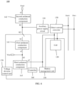
- FIG. 2 is a diagram of a structure of a battery pack according to an embodiment of this application.
- the battery pack 100 may include an auxiliary power supply circuit 110, a direct current converter 130, a cell 120, a first unilateral conduction component 141, and a second unilateral conduction component 142.
- a conduction electrode a1 of the first unilateral conduction component 141 is configured to receive a first direct current signal Vin1
- a conduction electrode a2 of the second unilateral conduction component 142 is configured to receive a second direct current signal Vin2
- a cut-off electrode b1 of the first unilateral conduction component 141 and a cut-off electrode b2 of the second unilateral conduction component 142 are connected to each other and then connected to the auxiliary power supply circuit 110.
- the auxiliary power supply circuit 110 is further connected to the direct current converter 130, a positive end of a battery connection port of the direct current converter 130 is connected to a first port (for example, a total positive port) of the cell 120, a negative end of the battery connection port of the direct current converter 130 is connected to a second port (for example, a total negative port) of the cell 120, a positive end of a bus connection port of the direct current converter 130 is connected to the positive direct current transmission line Aus+, and a negative end of the bus connection port of the direct current converter 130 is connected to the negative direct current transmission line Aus-.
- a first power supply voltage of the first direct current signal Vin1 is supplied to the auxiliary power supply circuit 110 via the first unilateral conduction component 141, to activate the auxiliary power supply circuit 110.
- a second power supply voltage of the second direct current signal Vin2 is supplied to the auxiliary power supply circuit 110 via the second unilateral conduction component 142, to activate the auxiliary power supply circuit 110.
- the first unilateral conduction component 141 serves as an activation path for activating the auxiliary power supply circuit 110
- the second unilateral conduction component 142 serves as another activation path for activating the auxiliary power supply circuit 110, so that a voltage source for activating the auxiliary power supply circuit 110 is input through a plurality of activation paths.
- the voltage for activating the auxiliary power supply circuit 110 can be input through another activation path, to ensure that the auxiliary power supply circuit 110 can be activated to operate, and improve reliability of the energy storage system.
- the auxiliary power supply circuit 110 performs boost or buck conversion on the input voltage and supplies power to the direct current converter 130, so that the direct current converter 130 operates. In this way, a battery voltage of the cell 120 is converted into a discharge voltage and the discharge voltage is output to the positive direct current transmission line Aus+ and the negative direct current transmission line Aus-, and the cell 120 can discharge.
- the battery control unit 220 transmits discharge voltages on the positive direct current transmission line Aus+ and the negative direct current transmission line Aus- to an inverter 210, and the inverter 210 converts the discharge voltages on the positive direct current transmission line Aus+ and the negative direct current transmission line Aus- into load voltages and outputs the load voltages to the load 300, to implement a process in which power is supplied to the load 300 via the energy storage system.
- the inverter 210 converts an input voltage into a first charge voltage and then outputs the first charge voltage to the battery control unit 220, and the battery control unit 220 converts the first charge voltage into a second power supply voltage, to activate the auxiliary power supply circuit 110.
- the auxiliary power supply circuit 110 After being activated, the auxiliary power supply circuit 110 performs boost or buck conversion on the input voltage and then supplies power to the direct current converter 130, so that the direct current converter 130 operates.
- first charge voltages on the positive direct current transmission line Aus+ and the negative direct current transmission line Aus- may be converted into second charge voltages, and the second charge voltages are output to the cell 120, to implement a process of charging the cell 120.
- FIG. 3 is a diagram of a structure of a battery pack according to another embodiment of this application.
- the battery pack 100 may further include the second switch K2.
- One end of the second switch K2 is connected to the conduction electrode a1 of the first unilateral conduction component 141, and the other end of the second switch K2 is connected to the cell 120, to receive the first direct current signal Vin1. That is, the second switch K2 is connected between the cell 120 and the conduction electrode a1 of the first unilateral conduction component 141.
- FIG. 3 is a diagram of a structure of a battery pack according to another embodiment of this application. Refer to FIG. 3 .
- the battery pack 100 may further include the second switch K2.
- One end of the second switch K2 is connected to the conduction electrode a1 of the first unilateral conduction component 141, and the other end of the second switch K2 is connected to the cell 120, to receive the first direct current signal Vin1. That is, the second switch K2 is connected between the cell 120 and the conduction electrode a1 of the first
- FIG. 4 is a diagram of a structure of a battery pack according to another embodiment of this application.
- One end of the second switch K2 is connected to the cut-off electrode b1 of the first unilateral conduction component 141, and the other end of the second switch K2 and the cut-off electrode b2 of the second unilateral conduction component 142 are connected to each other and then connected to the auxiliary power supply circuit 110. That is, the second switch K2 is connected at a connection point of the cut-off electrode b1 of the first unilateral conduction component 141 and the cut-off electrode b2 of the second unilateral conduction component 142.
- the second switch may be controlled by using software or a combination of software and hardware.
- the battery pack 100 further includes a controller 160.
- the controller 160 is communicatively connected and/or electrically connected to the second switch K2.
- the controller 160 obtains a port voltage between a first port and a second port of the cell 120, and controls the second switch based on the port voltage.
- the controller 160 may control the second switch K2 to be turned on.
- the second switch K2 may be turned off by default; or in response to that the port voltage is less than the first t voltage hreshold, the controller 160 directly controls the second switch K2 to be turned off.
- the first voltage threshold is A*B, where A represents a rated voltage of the cell 120, and B is a percentage.
- B is 50% to 100%.
- B may alternatively be another value. This is not limited herein.
- the second switch may be controlled by using hardware.
- the battery pack 100 further includes a voltage division control unit 170.
- the voltage division control unit 170 is electrically connected to the second switch K2; and in response to a current input, the voltage division control unit controls the second switch K2 to be turned on. Power may be supplied to the voltage division control unit via the cell.
- the voltage division control unit 170 is connected to the second port of the cell 120, and the voltage division control unit 170 is configured to connect to the first port of the cell 120 via a second switch. When the second switch is turned on, there is a current input in the voltage division control unit 170.
- the cell 120 inputs a current for the voltage division control unit 170, so that the second switch K2 can be controlled to be turned on via the voltage division control unit 170.
- the third unilateral conduction component 143 is used to prevent a cell in the battery pack from being directly connected to a cell in another battery pack, and prevent electricity of the cell in the another battery pack from flowing back to the cell in the battery pack.
- the voltage division control unit 170 includes a voltage division resistor R0, a Zener diode D0, and a metal-oxide-semiconductor (Metal-Oxide-Semiconductor, MOS) transistor M0.
- a voltage division resistor R0 a Zener diode D0
- MOS Metal-Oxide-Semiconductor
- a positive electrode of the Zener diode D0 is connected to the first port of the cell 120 via the first switch K1 and a branch of the third unilateral conduction component 143, a negative electrode of the Zener diode D0 is connected to a gate of the MOS transistor M0 and a first end of the voltage division resistor R0, a second end of the voltage division resistor R0 is connected to a source of the MOS transistor M0 and the second port of the cell 120, and a drain of the transistor M0 is connected to the second switch K2.
- the cell 120 inputs a current for the voltage division control unit 170, to control the transistor M0 to be turned on, and further to control the second switch K2 to be turned on.
- the first direct current signal Vin1 in this application may be provided by the cell 120.
- the first port (for example, a total positive port) of the cell 120 outputs the first direct current signal Vin1.
- the conduction electrode a1 of the first unilateral conduction component 141 is connected to the first port (for example, the total positive port) of the cell 120 via the second switch K2.
- the conduction electrode a1 of the first unilateral conduction component 141 is directly connected to the first port (for example, the total positive port) of the cell 120.
- the cut-off electrode b3 of the third unilateral conduction component 143 is further connected to the second switch K2, so that the first port (for example, the total positive port) of the cell 120 supplies power to the first direct current signal Vin1 via the third unilateral conduction component 143.
- the cut-off electrode of the third unilateral conduction component may be connected to the conduction electrode of the first unilateral conduction component. This is not limited herein.
- the first unilateral conduction component is configured to implement unilateral conduction of a current in a direction from the conduction electrode of the first unilateral conduction component to the cut-off electrode of the first unilateral conduction component.
- the current can flow into the conduction electrode of the first unilateral conduction component, and flow out of the cut-off electrode of the first unilateral conduction component. If the current flows into the cut-off electrode of the first unilateral conduction component, the current cannot flow out of the conduction electrode of the first unilateral conduction component.
- a diode may be used to form the first unilateral conduction component.
- the first unilateral conduction component includes a first diode.
- a positive electrode of the first diode is configured to receive the first direct current signal, and a negative electrode of the first diode is connected to the cut-off electrode of the second unilateral conduction component.
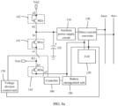
- FIG. 7a is a diagram of a structure of a battery pack according to another embodiment of this application. Refer to FIG. 7a .
- a positive electrode of a first diode D1 is configured to receive the first direct current signal Vin1 via the second switch K2, and a negative electrode of the first diode D1 and the cut-off electrode b2 of the second unilateral conduction component 142 are connected to each other and then connected to the auxiliary power supply circuit 110.
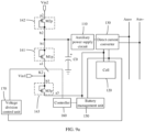
- FIG. 7b is a diagram of a structure of a battery pack according to another embodiment of this application. Refer to FIG. 7b .
- a positive electrode of a first diode D1 is configured to directly receive the first direct current signal Vin1, and a negative electrode of the first diode D1 and the cut-off electrode b2 of the second unilateral conduction component 142 are connected to each other via the second switch K2 and then connected to the auxiliary power supply circuit 110.
- the positive electrode of the first diode D1 serves as the conduction electrode a1 of the first unilateral conduction component 141
- the negative electrode of the first diode D1 serves as the cut-off electrode b1 of the first unilateral conduction component 141, to implement a unilateral conduction function.
- one first diode D1 is used as an example for illustration. During actual application, there may alternatively be two, three, or more first diodes D1 connected in series.
- the first diode D1 may be disposed as a PN junction diode, a PIN diode, or the like.
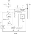
- FIG. 8b is a diagram of a structure of a battery pack according to another embodiment of this application. Refer to FIG. 8b .
- a gate and a drain of a first N-type transistor M1n are connected to each other and then configured to receive the first direct current signal Vin1, and a source of the first N-type transistor M1n and the cut-off electrode b2 of the second unilateral conduction component 142 are connected to each other via the second switch K2 and then connected to the auxiliary power supply circuit 110.
- a connection point at which the gate and the drain of the first N-type transistor M1n are connected to each other serves as the conduction electrode of the first unilateral conduction component 141, and the source of the first N-type transistor M1n serves as the cut-off electrode of the first unilateral conduction component 141, to implement a unilateral conduction function.
- first N-type transistor M1n is used as an example for illustration. During actual application, there may alternatively be two, three, or more first N-type transistors M1n connected in series. In addition, the first N-type transistor M1n may be disposed as an N-type metal-oxide-semiconductor (N Metal-Oxide-Semiconductor, NMOS) transistor.
- N Metal-Oxide-Semiconductor, NMOS N-type metal-oxide-semiconductor
- a P-type transistor may be used to form the first unilateral conduction component.
- the first unilateral conduction component includes a first P-type transistor.
- a gate and a drain of the first P-type transistor are connected to each other and then connected to the cut-off electrode of the second unilateral conduction component, and a source of the first P-type transistor is configured to receive the first direct current signal.
- FIG. 9a is a diagram of a structure of a battery pack according to another embodiment of this application. Refer to FIG. 9a .
- FIG. 9b is a diagram of a structure of a battery pack according to another embodiment of this application. Refer to FIG. 9b .
- a gate and a drain of a first P-type transistor M1p are connected to each other and then connected to the auxiliary power supply circuit 110 and the cut-off electrode b2 of the second unilateral conduction component 142 via the second switch K2, and a source of the first P-type transistor M1p is configured to directly receive the first direct current signal Vin1.
- a connection point at which the gate and the drain of the first P-type transistor M1p are connected to each other serves as the cut-off electrode of the first unilateral conduction component 141, and the source of the first P-type transistor M1p serves as the conduction electrode of the first unilateral conduction component 141, to implement a unilateral conduction function.
- one first P-type transistor M1p is used as an example for illustration. During actual application, there may alternatively be two, three, or more first P-type transistors M1p connected in series. In addition, the first P-type transistor M1p may be disposed as a P-type metal-oxide-semiconductor (P Metal-Oxide-Semiconductor, PMOS) transistor.
- P-type metal-oxide-semiconductor P Metal-Oxide-Semiconductor, PMOS
- the second unilateral conduction component is also configured to implement unilateral conduction of a current in a direction from the conduction electrode of the second unilateral conduction component to the cut-off electrode of the second unilateral conduction component.
- the current can flow into the conduction electrode of the second unilateral conduction component, and flow out of the cut-off electrode of the second unilateral conduction component. If the current flows into the cut-off electrode of the second unilateral conduction component, the current cannot flow out of the conduction electrode of the second unilateral conduction component.
- a diode may be used to form the second unilateral conduction component.
- the second unilateral conduction component 142 includes a second diode D2.
- a positive electrode of the second diode D2 is configured to receive the second direct current signal Vin2, and a negative electrode of the second diode D2 and the cut-off electrode b1 of the first unilateral conduction component 141 are connected to each other and then connected to the auxiliary power supply circuit 110.
- the positive electrode of the second diode D2 serves as the conduction electrode a2 of the second unilateral conduction component 142
- the negative electrode of the second diode D2 serves as the cut-off electrode b2 of the second unilateral conduction component 142, to implement a unilateral conduction function.
- one second diode D2 is used as an example for illustration. During actual application, there may alternatively be two, three, or more second diodes D2 connected in series.
- the second diode D2 may be disposed as a PN junction diode, a PIN diode, or the like.
- an N-type transistor may be used to form the second unilateral conduction component.
- the second unilateral conduction component 142 includes a second N-type transistor M2n.
- a gate and a drain of the second N-type transistor M2n are connected to each other and then configured to receive the second direct current signal Vin2, and a source of the second N-type transistor M2n and the cut-off electrode b1 of the first unilateral conduction component 141 are connected to each other and then connected to the auxiliary power supply circuit 110.
- a connection point at which the gate and the drain of the second N-type transistor M2n are connected to each other serves as the conduction electrode a2 of the second unilateral conduction component 142, and the source of the second N-type transistor M2n serves as the cut-off electrode b2 of the second unilateral conduction component 142, to implement a unilateral conduction function.
- one second N-type transistor M2n is used as an example for illustration. During actual application, there may alternatively be two, three, or more second N-type transistors M2n connected in series. In addition, the second N-type transistor M2n may be disposed as an NMOS transistor.
- a P-type transistor may be used to form the second unilateral conduction component.
- the second unilateral conduction component 142 includes a second P-type transistor M2p.
- a gate and a drain of the second P-type transistor M2p are connected to each other and then connected to the cut-off electrode b1 of the first unilateral conduction component 141, and a source of the second P-type transistor M2p is configured to receive the second direct current signal Vin2.
- a connection point at which the gate and the drain of the second P-type transistor M2p are connected to each other serves as the cut-off electrode b2 of the second unilateral conduction component 142, and the source of the second P-type transistor M2p serves as the conduction electrode a2 of the second unilateral conduction component 142, to implement a unilateral conduction function.
- one second P-type transistor M2p is used as an example for illustration. During actual application, there may alternatively be two, three, or more second P-type transistors M2p connected in series. In addition, the second P-type transistor M2p may be disposed as a PMOS transistor.
- the third unilateral conduction component is also configured to implement unilateral conduction of a current in a direction from the conduction electrode of the third unilateral conduction component to the cut-off electrode of the third unilateral conduction component.
- the current can flow into the conduction electrode of the third unilateral conduction component, and flow out of the cut-off electrode of the third unilateral conduction component. If the current flows into the cut-off electrode of the third unilateral conduction component, the current cannot flow out of the conduction electrode of the third unilateral conduction component.
- a diode may be used to form the third unilateral conduction component.
- the third unilateral conduction component 143 includes a third diode D3.
- a positive electrode of the third diode D3 is connected to the first port of the cell 120, and a negative electrode of the third diode D3 and a first end of the first switch are configured to receive the first direct current signal Vin1.
- the positive electrode of the third diode D3 serves as the conduction electrode a3 of the third unilateral conduction component 143
- the negative electrode of the third diode D3 serves as the cut-off electrode b3 of the third unilateral conduction component 143, to implement a unilateral conduction function.
- FIG. 1 the third unilateral conduction component 143
- one third diode D3 is used as an example for illustration. During actual application, there may alternatively be two, three, or more third diodes D3 connected in series. In addition, the third diode D3 may be disposed as a PN junction diode, a PIN diode, or the like.
- an N-type transistor may be used to form the third unilateral conduction component.
- the third unilateral conduction component 143 includes a third N-type transistor M3n.
- a gate and a drain of the third N-type transistor M3n are connected to each other and then connected to the first port (for example, a total positive port) of the cell 120, and a source of the third N-type transistor M3n is connected to the first end of the first switch and the second switch K2.
- a connection point at which the gate and the drain of the third N-type transistor M3n are connected to each other serves as the conduction electrode a3 of the third unilateral conduction component 143, and the source of the third N-type transistor M3n serves as the cut-off electrode b3 of the third unilateral conduction component 143, to implement a unilateral conduction function.
- one third N-type transistor M3n is used as an example for illustration. During actual application, there may alternatively be two, three, or more third N-type transistors M3n connected in series. In addition, the third N-type transistor M3n may be disposed as an NMOS transistor.
- a P-type transistor may be used to form the third unilateral conduction component.
- the third unilateral conduction component 143 includes a third P-type transistor M3p.
- a gate and a drain of the third P-type transistor M3p are configured to connect to the first end of the first switch and the second switch K2, and a source of the third P-type transistor M3p is connected to the first port (for example, a total positive port) of the cell 120.
- a connection point at which the gate and the drain of the third P-type transistor M3p are connected to each other serves as the cut-off electrode b3 of the third unilateral conduction component 143, and the source of the third P-type transistor M3p serves as the conduction electrode a3 of the third unilateral conduction component 143, to implement a unilateral conduction function.
- one third P-type transistor M3p is used as an example for illustration. During actual application, there may alternatively be two, three, or more third P-type transistors M3p connected in series. In addition, the third P-type transistor M3p may be disposed as a PMOS transistor.
- a voltage regulator capacitor C0 may be further disposed in the battery pack.
- the cut-off electrode b1 of the first unilateral conduction component 141 and the cut-off electrode b2 of the second unilateral conduction component 142 are connected to each other and then connected to one end of the voltage regulator capacitor C0, and the other end of the voltage regulator capacitor C0 is connected to a ground end, to maintain stability of an input voltage of the auxiliary power supply circuit 110, and improve operating stability.
- a battery management unit (Battery Management Unit, BMU) 150 may be further disposed in the battery pack 100.
- the BMU 150 is connected to the first port and the second port of the cell 120.
- the BMU 150 collects the port voltage between the first port and the second port of the cell 120, and sends the collected port voltage to the controller 160.
- the controller 160 may control the second switch K2 based on the port voltage.
- the BMU 150 may further collect a SOC, an SOH, a temperature, and the like of the cell 120.
- the auxiliary power supply circuit 110 and the direct current converter 130 may be separately disposed as a direct current-direct current (Direct Current-Direct Current, DC-DC) conversion circuit. Based on this, after being activated by supplying power via the first unilateral conduction component 141, the auxiliary power supply circuit 110 converts a voltage input by the first unilateral conduction component 141 into a drive voltage and then outputs the drive voltage to the direct current converter, so that the direct current converter converts a voltage of the cell into a discharge voltage and outputs the discharge voltage to the positive direct current transmission line Aus+ and the negative direct current transmission line Aus-.
- DC-DC direct current-direct current
- the auxiliary power supply circuit 110 converts a voltage input by the second unilateral conduction component 142 into a drive voltage and then outputs the drive voltage to the direct current converter, so that the direct current converter converts a voltage of the cell into a discharge voltage and outputs the discharge voltage to the positive direct current transmission line Aus+ and the negative direct current transmission line Aus-.
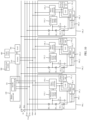
- FIG. 10 is a diagram of a structure of an energy storage system according to another embodiment of this application.
- Three battery packs 100_1, 100_2, and 100_3 are used as an example, and the battery packs 100_1 to 100_3 separately use the structure shown in FIG. 7a as an example.
- a positive electrode of a first diode D1_1 in the first unilateral conduction component 141 is connected to a first electrode (for example, a total positive electrode) of a cell 120_1 via a second switch K2_1, to output a first power supply voltage to the first diode D1_1 via the cell 120_1.
- a positive electrode of a first diode D1_2 in the first unilateral conduction component 141 is connected to a first electrode (for example, a total positive electrode) of a cell 120_2 via a second switch K2_2, to output a first power supply voltage to the first diode D1_2 via the cell 120_2.
- a positive electrode of a first diode D1_3 in the first unilateral conduction component 141 is connected to a first electrode (for example, a total positive electrode) of a cell 120_3 via a second switch K2_3, to output a first power supply voltage to the first diode D1_3 via the cell 120_3.
- the cell in the battery pack can serve as a voltage source of the first direct current signal, and an external power supply does not need to be additionally disposed for the first direct current signal. This reduces costs of activating the energy storage system, increases redundancy of the energy storage system, and improves reliability of the energy storage system.
- the energy storage system When the energy storage system does not operate, it is usually in a sleep state. Therefore, to wake up the energy storage system, with reference to FIG. 10 , the energy storage system further includes a first switch K1, a first switch connection line Kus+, and a second switch connection line Kus-. A first end of the first switch K1 is connected to the first switch connection line Kus+, and a second end of the first switch K1 is connected to the second switch connection line Kus-, to connect the first switch K1 between the first switch connection line Kus+ and the second switch connection line Kus-.
- conduction electrodes namely, positive electrodes of third diodes D3_1 to D3_3 of third unilateral conduction components in each battery pack 100_1 to 100_3 are connected to first ports (for example, total positive ports) of the cells 120_1 to 120_3, and cut-off electrodes (namely, negative electrodes of the third diodes D3_1 to D3_3) of the third unilateral conduction components in each battery pack 100_1 to 100_3 are connected to the first switch connection line Kus+, voltage division control units 170_1 to 170_3 in each battery pack are connected to the second switch connection line Kus-, and the voltage division control units 170_1 to 170_3 in each battery pack 100_1 to 100_3 are further connected to second ports (for example, total negative ports) of the cells 120_1 to 120_3.
- cut-off electrodes namely, negative electrodes of the third diodes D3_1 to D3_3 of the third unilateral conduction components in each battery pack 100_1 to 100_3 are connected to the first switch connection line
- the cell 120_1 is used as an example.
- the cell 120_1 may be used to supply power to the voltage division control unit 170_1 of the cell 120_1, to control the second switch K2_1 to be turned on.
- the other cells 120_2 and 120_3 may be used to supply power to the voltage division control unit 170_1 of the cell 120_1, to control the second switch K2_1 to be turned on.
- the first switch K1 may be integrated into the BCU 220.
- the first switch K1 may be manually controlled to be turned on and turned off.
- an operator may manually press a physical button or a virtual button to control the first switch K1 to be turned on, and the operator controls the first switch K1 to be turned off after the first switch K1 is controlled to be turned on for specified duration (for example, 3 seconds).
- the operator may manually press the physical button or the virtual button again to control the first switch K1 to be turned off.
- the first switch K1 may alternatively be controlled to be turned on and turned off in a software control manner.
- the BCU 220 controls the first switch K1 to be turned on, and controls the first switch K1 to be turned off after the first switch K1 is controlled to be turned on for specified duration (for example, 3 seconds).
- the BCU 220 may also control the first switch K1 to be turned off.
- the energy storage system further includes power supply transmission lines Cus (including a positive power supply transmission line Cus+ and a negative power supply transmission line Cus-).
- the negative power supply transmission line Cus- is connected to a ground end and negative ends of auxiliary power supply circuits 110_1 to 110_3, a positive end of the auxiliary power supply circuit 110_1 is connected to a negative electrode of the first diode D1_1 and a negative electrode of the second diode D2_1, a positive end of the auxiliary power supply circuit 110_2 is connected to a negative electrode of the first diode D1_2 and a negative electrode of the second diode D2_2, and a positive end of the auxiliary power supply circuit 110_3 is connected to a negative electrode of the first diode D1_3 and a negative electrode of the second diode D2_3.
- the BCU 220 is connected to the positive power supply transmission line Cus+ and the negative power supply transmission line Cus-.
- the BCU 220 may convert discharge voltages of the positive direct current transmission line Aus+ and the negative direct current transmission line Aus- into second power supply voltages and then output the second power supply voltages to the positive power supply transmission line Cus+ and the negative power supply transmission line Cus-, so that the positive power supply transmission line Cus+ and the negative power supply transmission line Cus- transmit the second power supply voltages to the second diodes D2_1 to D2_3.
- the BCU 220 includes a main circuit and a DC-DC conversion circuit 231.
- the DC-DC conversion circuit 231 is connected to the positive direct current transmission line Aus+, the negative direct current transmission line Aus-, the main circuit, the positive power supply transmission line Cus+, and the negative power supply transmission line Cus-, and the DC-DC conversion circuit 231 may convert a discharge voltage into a second power supply voltage, and not only supply power to second direct current signals Vin2_1 to Vin2_3 but also supply power to the main circuit based on the second power supply voltage.
- the energy storage system When the power system 400 supplies power to the load 300, the energy storage system is usually in a sleep state. After the power system 400 is powered off, the energy storage system needs to be activated, to supply power to the load 300 via the energy storage system. The following describes a process of activating the energy storage system to supply power to the load 300.
- the first switch K1 is controlled to be turned on for specific duration (for example, 3 seconds), and currents are input to the voltage division control units 170_1 to 170_3 in each battery pack 100_1 to 100_3, so that the second switches K2_1 to K2_3 are controlled to be turned on.
- an operating process of the battery packs 100_1 to 100_3 is as follows: The following uses the battery pack 100_1 as an example.
- the cell 120_1 provides a first power supply voltage for the first diode D1_1 via the third diode D3_1, so that the first diode D1_1 supplies power to the auxiliary power supply circuit 110_1.
- the auxiliary power supply circuit 110_1 is activated, so that the auxiliary power supply circuit 110_1 supplies power to a direct current converter 130_1, a BMU 150_1, and a controller 160_1.
- the BMU 150_1 sends a collected port voltage VD_1 of the cell 120_1 to the controller 160_1. If the port voltage VD_1 is not less than the first voltage threshold, the controller 160_1 also controls the second switch K2_1 to be turned on. Then, if the first switch K1 is turned off, the controller 160_1 may continue to control the second switch K2_1 to be turned on. In this way, the auxiliary power supply circuit 110_1 continues to supply power to the direct current converter 130_1, the BMU 150_1, and the controller 160_1.
- the direct current converter 130_1 operates after being supplied power, converts a battery voltage of the cell 120_1 into a discharge voltage, and outputs the discharge voltage to the positive direct current transmission line Aus+ and the negative direct current transmission line Aus-, so that the cell 120_1 can discharge.
- the BCU 220 further converts the discharge voltage into the second power supply voltage and outputs the second power supply voltage to the second diode D2_1. Based on this, the first power supply voltage is input to the positive electrode of the first diode D1_1, and the second power supply voltage is input to a positive electrode of the second diode D2_1.
- the negative electrode of the first diode D1_1 and the negative electrode of the second diode D2_1 are connected together to form a counter-parallel arrangement. Therefore, when the first power supply voltage is greater than the second power supply voltage, power may be supplied to the auxiliary power supply circuit 110_1 through a path of the first diode D1_1. When the second power supply voltage is greater than the first power supply voltage, power may be supplied to the auxiliary power supply circuit 110_1 through a path of the second diode D2_1, so that the auxiliary power supply circuit 110_1 continues to supply power to the direct current converter 130_1, the BMU 150_1, and the controller 160_1, thereby implementing a process in which the cell 120_1 continues to discharge.
- the inverter 210 converts the discharge voltage into a load voltage and then outputs the load voltage to the load 300, to supply power to the load 300.
- the battery packs 100_2 and 100_3 refer to the operating process of the battery pack 100_1. Details are not described herein again.
- an operating process of the battery packs 100_1 to 100_3 is as follows: For an operating process of the battery pack 100_2 and the battery pack 100_3, refer to an operating process of the foregoing battery pack 100_1. Details are not described herein again. The following describes the battery pack 100_1. Because the voltage of the cell 120_1 is insufficient, the first power supply voltage cannot be provided for the first diode D1_1 via the third diode D3_1. As a result, the auxiliary power supply circuit 110_1 cannot be activated.
- the BCU 220 After converting the discharge voltage into the second power supply voltage, the BCU 220 also outputs the second power supply voltage to the second diode D2_1, so that power can be supplied to the auxiliary power supply circuit 110_1 via the second diode D2_1. In this way, the auxiliary power supply circuit 110_1 is activated, so that the auxiliary power supply circuit 110_1 supplies power to the direct current converter 130_1, the BMU 150_1, and the controller 160_1.
- the direct current converter 130_1 operates after being supplied power, converts a battery voltage of the cell 120_1 into a discharge voltage, and outputs the discharge voltage to the positive direct current transmission line Aus+ and the negative direct current transmission line Aus-, so that the cell 120_1 can discharge. Based on this, the inverter 210 converts the discharge voltage into a load voltage and then outputs the load voltage to the load 300, to supply power to the load 300.
- the battery voltage of the cell 120_1 is insufficient for discharging, and the direct current converter 130_1 is temporarily in a standby state, and performs a charge operation process after receiving a charge instruction.
- a photovoltaic module 500 is further disposed in the energy storage system, and the photovoltaic module 500 can output a direct current, to charge a cell in the energy storage system.
- the following describes a process of charging a cell in the energy storage system.
- the inverter 210 obtains power from the photovoltaic module 500, converts a direct current voltage output by the photovoltaic module 500 into a first charge voltage, and outputs the first charge voltage to the battery control unit 220.
- the battery control unit 220 outputs the first charge voltage to the positive direct current transmission line Aus+ and the negative direct current transmission line Aus-.
- the BCU 220 converts the discharge voltage into the second power supply voltage and outputs the second power supply voltage to positive electrodes of the second diodes D2_1 to D2_3.
- the first battery pack 100_1 is used as an example.
- the second power supply voltage is supplied to the auxiliary power supply circuit 110_1 via the second diode D2_1, to activate the auxiliary power supply circuit 110_1, so that the auxiliary power supply circuit 110_1 supplies power to the direct current converter 130_1, the BMU 150_1, and the controller 160_1.
- the direct current converter 130_1 operates after being supplied power, converts first charge voltages on the positive direct current transmission line Aus+ and the negative direct current transmission line Aus- into the second charge voltage, and outputs the second charge voltage to the cell 120_1, to charge the cell 120_1.
- the BMU 150_1 and the controller 160_1 are also powered on, the BMU 150_1 sends the collected port voltage VD_1 of the cell 120_1 to the controller 160_1.
- the second switch K2_1 cannot be controlled to be turned on. Until the port voltage VD_1 is not less than the first voltage threshold, the controller 160_1 can control the second switch K2_1 to be turned on. Based on this, the first power supply voltage is input to the positive electrode of the first diode D1_1, and the second power supply voltage is input to the positive electrode of the second diode D2_1.
- the negative electrode of the first diode D1_1 and the negative electrode of the second diode D2_1 are connected together to form a counter-parallel arrangement.
- the auxiliary power supply circuit 110_1 when the first power supply voltage is greater than the second power supply voltage, power may be supplied to the auxiliary power supply circuit 110_1 through the path of the first diode D 1_1.
- the second power supply voltage is greater than the first power supply voltage
- power may be supplied to the auxiliary power supply circuit 110_1 through a path of the second diode D2_1, so that the auxiliary power supply circuit 110_1 continues to supply power to the direct current converter 130_1, the BMU 150_1, and the controller 160_1, thereby implementing a process of continuing to charge the cell 120_1.
- the battery packs 100_2 and 100_3 for an operating process of the battery packs 100_2 and 100_3, refer to the operating process of the battery pack 100_1. Details are not described herein again.
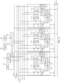
- FIG. 11 is a diagram of a structure of an energy storage system according to another embodiment of this application.
- a first interface WB1 may be further disposed in the energy storage system.
- the first interface WB 1 is configured to connect to an external power supply, and the external power supply inputs a first direct current signal for the battery pack through the first interface WB1.
- the positive electrode of the first diode D1_1 in the battery packs 100_1 to 100_3 is connected to a positive end of the first interface WB1 via the second switch K2_1, and second ports (for example, a total negative port) in the cells 120_1 to 120_3 are connected to a negative end of the first interface WB 1.
- the external power supply may be a direct current power supply.
- the two manners may coexist in the energy storage system, or one of the two manners may exist. This is not limited herein. It may be understood that, for an operating process of the energy storage system in this embodiment, refer to the foregoing embodiments. Details are not described herein again.
- the first interface WB1 may be integrated into the BCU 220.
- the first interface WB 1 may be integrated into each battery pack.
- a first interface WB 1 is integrated into each battery pack, and a first interface WB 1 is also integrated into the BCU 220, and the first interface WB 1 of the battery pack is aggregated to the first interface WB 1 in the BCU 220.
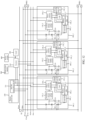
- FIG. 12 is a diagram of a structure of an energy storage system according to another embodiment of this application.
- a second interface WB2 may be further disposed in the energy storage system.
- the second interface WB2 is configured to connect to an external power supply, and the external power supply inputs a second direct current signal for the battery pack through the second interface WB2.
- the positive power supply transmission line Cus+ is connected to a positive end of the second interface WB2
- the negative power supply transmission line Cus- is connected to a negative end of the second interface WB2.
- the external power supply may be a direct current power supply.
- both manners may coexist in the energy storage system, or one of the manners may exist. This is not limited herein. It may be understood that, for an operating process of the energy storage system in this embodiment, refer to the foregoing embodiments. Details are not described herein again.
- the second interface WB2 may be integrated into the BCU 220.
- the second interface WB2 may be integrated into each battery pack.
- a second interface WB2 is integrated into each battery pack, and a second interface WB2 is also integrated into the BCU 220, and the second interface WB2 of the battery pack is aggregated to the second interface WB2 in the BCU 220.
- An embodiment of this application further provides a power supply method for an energy storage system.
- the method includes: in response to that a first power supply voltage of a first direct current signal is greater than a second power supply voltage of a second direct current signal, activating an auxiliary power supply circuit via a first unilateral conduction component to supply power to a direct current converter; or in response to that the second power supply voltage is greater than the first power supply voltage, activating the auxiliary power supply circuit via a second unilateral conduction component to supply power to the direct current converter.
- a battery voltage of a cell is converted into a discharge voltage and then the discharge voltage is output.
- an inverter converts the discharge voltage into a load voltage and then outputs the load voltage to a load, to supply power to the load.
- An embodiment of this application further provides a charge method for an energy storage system.
- the method includes: An inverter converts an input voltage into a first charge voltage and then outputs the first charge voltage to a battery control unit; and the battery control unit converts the first charge voltage into a second power supply voltage and then outputs the second power supply voltage to power supply transmission lines, so that a second unilateral conduction component activates, based on the second power supply voltage, an auxiliary power supply circuit to supply power to a direct current converter. Based on this, the direct current converter converts the first charge voltage into a second charge voltage and then outputs the second charge voltage to a cell, to charge the cell.
Landscapes
- Engineering & Computer Science (AREA)
- Power Engineering (AREA)
- Microelectronics & Electronic Packaging (AREA)
- Manufacturing & Machinery (AREA)
- Chemical & Material Sciences (AREA)
- Chemical Kinetics & Catalysis (AREA)
- Electrochemistry (AREA)
- General Chemical & Material Sciences (AREA)
- Charge And Discharge Circuits For Batteries Or The Like (AREA)
Applications Claiming Priority (1)
| Application Number | Priority Date | Filing Date | Title |
|---|---|---|---|
| CN202310961415.4A CN117200416A (zh) | 2023-07-31 | 2023-07-31 | 一种电池包、储能系统及供电方法 |
Publications (3)
| Publication Number | Publication Date |
|---|---|
| EP4503363A1 true EP4503363A1 (de) | 2025-02-05 |
| EP4503363B1 EP4503363B1 (de) | 2026-01-28 |
| EP4503363C0 EP4503363C0 (de) | 2026-01-28 |
Family
ID=89002495
Family Applications (1)
| Application Number | Title | Priority Date | Filing Date |
|---|---|---|---|
| EP24188001.2A Active EP4503363B1 (de) | 2023-07-31 | 2024-07-11 | Batteriepack, energiespeichersystem und stromversorgungsverfahren |
Country Status (2)
| Country | Link |
|---|---|
| EP (1) | EP4503363B1 (de) |
| CN (1) | CN117200416A (de) |
Citations (7)
| Publication number | Priority date | Publication date | Assignee | Title |
|---|---|---|---|---|
| US6208117B1 (en) * | 1999-07-30 | 2001-03-27 | Fujitsu Limited | Battery pack and electronic apparatus using the same |
| GB2467231A (en) * | 2009-01-27 | 2010-07-28 | Hitachi Ltd | High voltage battery controller with isolation |
| US20190319472A1 (en) * | 2016-11-30 | 2019-10-17 | Bombardier Recreational Products Inc. | Electric system and method for energizing the electric system |
| EP3712007A1 (de) * | 2018-11-16 | 2020-09-23 | Contemporary Amperex Technology Co., Limited | Umwandlungsschaltung, batterieausgleichssystem und batterieverwaltungssystem |
| CN212012176U (zh) * | 2020-04-09 | 2020-11-24 | 苏州山倍能源科技有限公司 | 一种电池管理系统 |
| WO2022163475A1 (ja) * | 2021-01-27 | 2022-08-04 | 三洋電機株式会社 | 電源装置 |
| EP4199295A1 (de) * | 2021-06-30 | 2023-06-21 | Huawei Digital Power Technologies Co., Ltd. | Energiespeichervorrichtung, steuerungsverfahren für energiespeichervorrichtung und fotovoltaisches system |
-
2023
- 2023-07-31 CN CN202310961415.4A patent/CN117200416A/zh active Pending
-
2024
- 2024-07-11 EP EP24188001.2A patent/EP4503363B1/de active Active
Patent Citations (7)
| Publication number | Priority date | Publication date | Assignee | Title |
|---|---|---|---|---|
| US6208117B1 (en) * | 1999-07-30 | 2001-03-27 | Fujitsu Limited | Battery pack and electronic apparatus using the same |
| GB2467231A (en) * | 2009-01-27 | 2010-07-28 | Hitachi Ltd | High voltage battery controller with isolation |
| US20190319472A1 (en) * | 2016-11-30 | 2019-10-17 | Bombardier Recreational Products Inc. | Electric system and method for energizing the electric system |
| EP3712007A1 (de) * | 2018-11-16 | 2020-09-23 | Contemporary Amperex Technology Co., Limited | Umwandlungsschaltung, batterieausgleichssystem und batterieverwaltungssystem |
| CN212012176U (zh) * | 2020-04-09 | 2020-11-24 | 苏州山倍能源科技有限公司 | 一种电池管理系统 |
| WO2022163475A1 (ja) * | 2021-01-27 | 2022-08-04 | 三洋電機株式会社 | 電源装置 |
| EP4199295A1 (de) * | 2021-06-30 | 2023-06-21 | Huawei Digital Power Technologies Co., Ltd. | Energiespeichervorrichtung, steuerungsverfahren für energiespeichervorrichtung und fotovoltaisches system |
Also Published As
| Publication number | Publication date |
|---|---|
| EP4503363B1 (de) | 2026-01-28 |
| CN117200416A (zh) | 2023-12-08 |
| EP4503363C0 (de) | 2026-01-28 |
Similar Documents
| Publication | Publication Date | Title |
|---|---|---|
| CN104285351B (zh) | 作为两端口网络的能量供应模块,分离器件在该能量供应模块中的使用以及该能量供应模块的操作方法 | |
| CN113972817B (zh) | 固态变压器故障处理系统 | |
| US8294435B2 (en) | Power supply apparatus supplying power stored in power storage unit to load and power supply system including power supply apparatus | |
| US20140103723A1 (en) | Maximum power point controller transistor driving circuitry and associated methods | |
| CN114006433A (zh) | 电池装置 | |
| US8384356B2 (en) | Self contained power source | |
| CN102684301B (zh) | 电能管理系统和电能传输方法 | |
| CN117595449A (zh) | 一种充放电控制装置、充电控制方法及放电控制方法 | |
| EP4503363B1 (de) | Batteriepack, energiespeichersystem und stromversorgungsverfahren | |
| CN209313501U (zh) | 一种基于理想二极管的双电池组并联隔离电路 | |
| EP4270703A1 (de) | Elektrochemische vorrichtung mit langem bereitschaftsbetrieb, energiespeichersystem und elektrofahrzeug | |
| JP4767976B2 (ja) | 直流電源システム | |
| CN219678160U (zh) | 一种电池的无极性安装装置和移动式电子消费类设备 | |
| CN112803085A (zh) | 智慧电池 | |
| CN114094684B (zh) | 一种用于给电池充电的架构 | |
| WO2012133186A1 (ja) | スイッチ回路制御部及び充放電システム | |
| CN101420123A (zh) | 一种防止蓄电池反接的太阳能控制器 | |
| CN205622277U (zh) | 一种便携设备的电源电路 | |
| CN206948184U (zh) | 一种用于电池开关控制电路的升压电路 | |
| WO2006136100A1 (en) | Power supplying device and power supplying method | |
| CN222052627U (zh) | 电池包和储能电源 | |
| CN119727051B (zh) | 充放电控制电路及电池管理系统 | |
| CN205829243U (zh) | 一种电源电路 | |
| CN223559496U (zh) | 一种供电电路 | |
| CN224163734U (zh) | 电压采集电路及卫星电源系统 |
Legal Events
| Date | Code | Title | Description |
|---|---|---|---|
| PUAI | Public reference made under article 153(3) epc to a published international application that has entered the european phase |
Free format text: ORIGINAL CODE: 0009012 |
|
| STAA | Information on the status of an ep patent application or granted ep patent |
Free format text: STATUS: THE APPLICATION HAS BEEN PUBLISHED |
|
| AK | Designated contracting states |
Kind code of ref document: A1 Designated state(s): AL AT BE BG CH CY CZ DE DK EE ES FI FR GB GR HR HU IE IS IT LI LT LU LV MC ME MK MT NL NO PL PT RO RS SE SI SK SM TR |
|
| STAA | Information on the status of an ep patent application or granted ep patent |
Free format text: STATUS: REQUEST FOR EXAMINATION WAS MADE |
|
| 17P | Request for examination filed |
Effective date: 20250805 |
|
| GRAP | Despatch of communication of intention to grant a patent |
Free format text: ORIGINAL CODE: EPIDOSNIGR1 |
|
| STAA | Information on the status of an ep patent application or granted ep patent |
Free format text: STATUS: GRANT OF PATENT IS INTENDED |
|
| INTG | Intention to grant announced |
Effective date: 20250929 |
|
| RAP3 | Party data changed (applicant data changed or rights of an application transferred) |
Owner name: HUAWEI DIGITAL POWER TECHNOLOGIES CO. LTD. |
|
| GRAS | Grant fee paid |
Free format text: ORIGINAL CODE: EPIDOSNIGR3 |
|
| GRAA | (expected) grant |
Free format text: ORIGINAL CODE: 0009210 |
|
| STAA | Information on the status of an ep patent application or granted ep patent |
Free format text: STATUS: THE PATENT HAS BEEN GRANTED |
|
| AK | Designated contracting states |
Kind code of ref document: B1 Designated state(s): AL AT BE BG CH CY CZ DE DK EE ES FI FR GB GR HR HU IE IS IT LI LT LU LV MC ME MK MT NL NO PL PT RO RS SE SI SK SM TR |
|
| REG | Reference to a national code |
Ref country code: CH Ref legal event code: F10 Free format text: ST27 STATUS EVENT CODE: U-0-0-F10-F00 (AS PROVIDED BY THE NATIONAL OFFICE) Effective date: 20260128 Ref country code: GB Ref legal event code: FG4D |
|
| REG | Reference to a national code |
Ref country code: IE Ref legal event code: FG4D |
|
| U01 | Request for unitary effect filed |
Effective date: 20260128 |
|
| U07 | Unitary effect registered |
Designated state(s): AT BE BG DE DK EE FI FR IT LT LU LV MT NL PT RO SE SI Effective date: 20260203 |