EP4503384A1 - Flugzeugbauteil mit integriertem elektrischen system - Google Patents
Flugzeugbauteil mit integriertem elektrischen system Download PDFInfo
- Publication number
- EP4503384A1 EP4503384A1 EP23315304.8A EP23315304A EP4503384A1 EP 4503384 A1 EP4503384 A1 EP 4503384A1 EP 23315304 A EP23315304 A EP 23315304A EP 4503384 A1 EP4503384 A1 EP 4503384A1
- Authority
- EP
- European Patent Office
- Prior art keywords
- wireless power
- power transfer
- transfer module
- aircraft
- electrical
- Prior art date
- Legal status (The legal status is an assumption and is not a legal conclusion. Google has not performed a legal analysis and makes no representation as to the accuracy of the status listed.)
- Pending
Links
Images


Classifications
-
- H—ELECTRICITY
- H02—GENERATION; CONVERSION OR DISTRIBUTION OF ELECTRIC POWER
- H02J—ELECTRIC POWER NETWORKS; CIRCUIT ARRANGEMENTS OR SYSTEMS FOR SUPPLYING OR DISTRIBUTING ELECTRIC POWER; SYSTEMS FOR STORING ELECTRIC ENERGY
- H02J50/00—Circuit arrangements or systems for wireless supply or distribution of electric power
- H02J50/10—Circuit arrangements or systems for wireless supply or distribution of electric power using inductive coupling
-
- H—ELECTRICITY
- H02—GENERATION; CONVERSION OR DISTRIBUTION OF ELECTRIC POWER
- H02J—ELECTRIC POWER NETWORKS; CIRCUIT ARRANGEMENTS OR SYSTEMS FOR SUPPLYING OR DISTRIBUTING ELECTRIC POWER; SYSTEMS FOR STORING ELECTRIC ENERGY
- H02J50/00—Circuit arrangements or systems for wireless supply or distribution of electric power
- H02J50/40—Circuit arrangements or systems for wireless supply or distribution of electric power using two or more transmitting or receiving devices
- H02J50/402—Circuit arrangements or systems for wireless supply or distribution of electric power using two or more transmitting or receiving devices the two or more transmitting or the two or more receiving devices being integrated in the same unit, e.g. power mats with several coils or antennas with several sub-antennas
-
- H—ELECTRICITY
- H02—GENERATION; CONVERSION OR DISTRIBUTION OF ELECTRIC POWER
- H02J—ELECTRIC POWER NETWORKS; CIRCUIT ARRANGEMENTS OR SYSTEMS FOR SUPPLYING OR DISTRIBUTING ELECTRIC POWER; SYSTEMS FOR STORING ELECTRIC ENERGY
- H02J2105/00—Networks for supplying or distributing electric power characterised by their spatial reach or by the load
- H02J2105/30—Networks for supplying or distributing electric power characterised by their spatial reach or by the load the load networks being external to vehicles, i.e. exchanging power with vehicles
- H02J2105/32—Networks for supplying or distributing electric power characterised by their spatial reach or by the load the load networks being external to vehicles, i.e. exchanging power with vehicles for aircrafts
-
- H—ELECTRICITY
- H02—GENERATION; CONVERSION OR DISTRIBUTION OF ELECTRIC POWER
- H02J—ELECTRIC POWER NETWORKS; CIRCUIT ARRANGEMENTS OR SYSTEMS FOR SUPPLYING OR DISTRIBUTING ELECTRIC POWER; SYSTEMS FOR STORING ELECTRIC ENERGY
- H02J50/00—Circuit arrangements or systems for wireless supply or distribution of electric power
- H02J50/005—Mechanical details of housing or structure aiming to accommodate the power transfer means, e.g. mechanical integration of coils, antennas or transducers into emitting or receiving devices
-
- H—ELECTRICITY
- H02—GENERATION; CONVERSION OR DISTRIBUTION OF ELECTRIC POWER
- H02J—ELECTRIC POWER NETWORKS; CIRCUIT ARRANGEMENTS OR SYSTEMS FOR SUPPLYING OR DISTRIBUTING ELECTRIC POWER; SYSTEMS FOR STORING ELECTRIC ENERGY
- H02J7/00—Circuit arrangements for charging or discharging batteries or for supplying loads from batteries
- H02J7/60—Circuit arrangements for charging or discharging batteries or for supplying loads from batteries including safety or protection arrangements
- H02J7/663—Circuit arrangements for charging or discharging batteries or for supplying loads from batteries including safety or protection arrangements using battery or load disconnect circuits
Definitions
- the invention relates to an aircraft component.
- the invention further relates to a wireless power transmission arrangement and an aircraft.
- Modern aircraft include a variety of electrical systems that can range from systems important to aircraft control to passenger convenience.
- the integrated energy storage is typically supplied using plugs and connectors as well as cables or conductors within the structure.
- the invention provides an aircraft component, preferably a structural component or an interior component, the aircraft component comprising:
- the wireless power transfer module comprises a coil member that is embedded in the body portion and electrically coupled to the electrical apparatus.
- the wireless power transfer module comprises a plurality of coil members that is electrically coupled in parallel, and each coil member is electrically coupled to one electrical apparatus.
- the wireless power transfer module comprises a plurality of coil members being electrically coupled in series, and at least two coil members are electrically coupled to one electrical apparatus.
- the wireless power transfer module comprises a plurality of coil members where some of the coil members are electrically coupled in series and some of the coil members are electrically coupled in parallel, and each electrical apparatus is electrically coupled to both parallel and series coil members.
- each coil member is formed by litz wire that is embedded in the body portion or wherein each coil member is formed by a conductive path on a foil member that embedded in the body portion.
- the wireless power transfer module comprises at least one magnetic core that is integrated in the body portion and at least one coil member that encircles the magnetic core.
- the coil member has a circle-like or a rectangular outer contour.
- the coil member is formed by a conductive trace on a substrate.
- the coil member is formed by a conductive trace on a substrate.
- the conductive trace has a first trace portion and a second trace portion.
- the first trace portion is disposed on a first substrate surface or first intermediate layer of the substrate.
- the second trace portion is formed on a second substrate surface or second intermediate layer of the substrate that are different from the respective first substrate surface and first intermediate layer.
- the first trace portion and the second trace portion electrically coupled in series or in parallel.
- the coil member being formed by a plurality of conductive traces on a substrate.
- the conductive traces are pairwise electrically isolated.
- each conductive trace has a first trace portion and a second trace portion, wherein the first trace portion is disposed on a first substrate surface or first intermediate layer of the substrate and the second trace portion is formed on a second substrate surface or second intermediate layer of the substrate that are different from the respective first substrate surface and first intermediate layer.
- the first trace portion and the second trace portion electrically coupled in series, and each conductive trace crosses another conductive trace in different layers forming a braid-like structure.
- the wireless power transfer module comprises an electrical switch arrangement configured for selectively coupling the coil members in parallel, in series, or decoupling one or more coil members from other coil members.
- the wireless power transfer module comprises an AC-DC-converter configured for converting the wirelessly received electrical power to DC-power for supplying the electrical apparatus.
- the wireless power transfer module comprises at least one electrical switch configured for selectively coupling or decoupling the wireless power transfer module to each electrical apparatus.
- the wireless power transfer module comprises a controller configured for controlling the wireless power transfer module based on a sensor input.
- the controller is configured to control the output power of the wireless power transfer module in accordance with a power demand of the electrical apparatus.
- the controller is configured to control the output power by selectively electrically coupling or decoupling a number of coil members to its output.
- the wireless power transfer module comprises a current sensor that is configured to measure the current demand of the electrical apparatus.
- each electrical apparatus comprises an energy storage apparatus configured for storing electrical energy.
- each electrical apparatus comprises a DC-DC converter configured for adapting received DC-power to be used in the electrical apparatus.
- each electrical apparatus comprises a flight related sensor that is configured for measuring flight data indicative of the flight state of the aircraft.
- each electrical apparatus comprises a geoinformation sensor that is configured for measuring geoinformation data that is indicative of the ground environment below the aircraft.
- each electrical apparatus comprises an environmental sensor that is configured for measuring environmental data that is indicative of the environment around the aircraft.
- each electrical apparatus comprises a combined sensor that is configured to act as a combination of any of the flight related sensor, the geoinformation sensor, and the environmental sensor.
- the aircraft component is an interior component of a passenger cabin of an aircraft.
- the body portion is configured as a tray that is movable between a stowed position, in which the wireless power transfer module is deactivated, and an operating position, in which each wireless power transfer module is activated to allow wireless charging of a personal device deposited on the tray, wherein preferably the wireless power transfer module is integrated in the tray.
- the invention provides a wireless power transfer arrangement comprising a preferred aircraft component and a second wireless power transfer module that is configured to be inductively coupled to the wireless power transfer module to transmit electrical power thereto.
- the invention provides an aircraft, preferably a UAV, comprising a preferred aircraft component and/or a preferred wireless power transfer arrangement.
- the aircraft comprises an electrical propulsion system
- the electrical apparatus is configured for supplying electrical power to the electrical propulsion system.
- an aircraft component preferably a structural component or an interior component comprises a body portion; a wireless power transfer module being configured for wirelessly transmitting and/or receiving electrical power by induction; and at least one electrical apparatus being electrically coupled to the wireless power transfer module to supply or be supplied with the electrical power through the wireless power transfer module.
- the wireless power transfer module is integrated into the body portion. In some embodiments each electrical apparatus is integrated onto the body portion.
- the wireless power transfer module comprises at least one coil member being electrically coupled to the electrical apparatus.
- the wireless power transfer module comprises a plurality of coil members being electrically coupled in parallel.
- each coil member is electrically coupled to one electrical apparatus.
- the wireless power transfer module comprises a plurality of coil members being electrically coupled in series. Preferably, at least two coil members are electrically coupled to one electrical apparatus.
- each electrical apparatus comprises an AC-DC-converter configured for converting the electrical power received by induction to DC-power.
- each electrical apparatus comprises an energy storage apparatus and/or a sensor.
- the wireless power transfer module comprises at least one electrical switch configured for selectively coupling or decoupling the wireless power transfer module each electrical apparatus.
- the wireless power transfer module comprises an electrical switch arrangement configured for selectively coupling the coil members in parallel, in series, or decoupling one or more coil members from other coil members.
- the aircraft component is a structural component of an aircraft, preferably of an unmanned aerial vehicle.
- the electrical apparatus comprises a controller configured for controlling the wireless power transfer module based on a sensor input.
- the aircraft component is an interior component of a passenger cabin of an aircraft.
- the body portion is configured as a tray that is movable between a stowed position and an operating position, wherein the wireless power transfer module is integrated in the tray to allow charging of a personal device.
- the wireless power transfer module is energized in the operating position and deenergized in the stowed position.
- high power transfer for wireless charging of a UAV is possible.
- embedding of a serial network foil with coils in thermoplastic composite to simplify recycling is possible.
- the coils can be integrated into the structural material, e.g., the secondary structure.
- the structural material is or includes thermoplastic material.
- a structural embedding of ferrite in the secondary composite structure is possible.
- the realisation of coils on PEI foil material is possible.
- the PEI foil is particularly suitable for bonding to epoxy resins.
- the use of switch connectors is proposed to supply the coils after activation by the passenger.
- a low power transfer is proposed, e.g., by serial connection of several coils allowing to transfer power to receivers at different locations.
- a support e.g. foil, with sensors, electronics, wireless data transfer, or energy storage can be installed on the aircraft.
- inductive resonant charging can be performed by placing a primary coil in proximity on demand, e.g., when aircraft is on ground.
- the coils can be arranged in the aircraft wing, e.g. along a spar.
- the transferred power can be tapped along the length of the coil to supply inaccessible loads.
- the coils may be connected in series or parallel, preferably depending on load configuration.
- the coils may be used to power an active load (e.g. sensor) or charge a storage element for future use.
- a closed loop control implementation is in place.
- the coil configuration can be switched by detecting the resonant current in the coils, so that their current rating is respected.
- the system is configured for opposite operation.
- distributed coils are disposed in floor panels or in the cabin serving as primary coils to transfer power to individual passenger seats, e.g. to charge mobile devices.
- the support foil is equipped with switches for each coil. In some embodiments, manual switching is possible based on user needs.
- the coils may be integrated into cabin lining panels offering wireless power supply to passengers' personal devices. In some embodiments passengers can move down their tray thereby activating the switch to charge personal devices by wireless power transfer.
- the circuits can be formed by directly printing (e.g. by inkjet, aerosol jet, cold spray, screen printing or a combination thereof) of coils and dielectric material on ferroelectric material.
- directly printing e.g. by inkjet, aerosol jet, cold spray, screen printing or a combination thereof
- An additive manufacturing approach may save material resources, simplify the manufacturing process, allow for a reduction of installation time and/or allow weight savings.
- the wireless power transfer arrangement 10 comprises an aircraft component 12.
- the aircraft component 12 may be configured as a structural element of an aircraft (not depicted). Examples for structural elements are frames, stringers, stiffening elements, skin panels and other members that are typically part of the primary or secondary structure of the aircraft.
- the aircraft component 12 may be an interior component of the aircraft, such as a cabin monument, a passenger seat and accessories, a galley, a bathroom, an overhead compartment, a cabin separator and/or cabin panels.
- the aircraft component 12 comprises a body portion 14 that is preferably configured as a laminate structure.
- the body portion 14 may be manufactured from fibre reinforced plastic or other composite materials.
- the aircraft component 12 comprises a wireless power transfer module 16.
- the wireless power transfer module 16 is at least partially integrated in the body portion 14.
- the wireless power transfer module 16 is configured for wirelessly transmitting and/or receiving electrical power by means of an alternating electromagnetic field.
- the wireless power transfer module 16 comprises at least one coil member 18. As indicated in Fig. 1 , a plurality of coil members 18 can be electrically coupled together in parallel.
- the aircraft component 12 further comprises an electrical apparatus 20.
- the electrical apparatus 20 may be integrated into the body portion 14. It is also possible that the electrical apparatus 20 is arranged in the vicinity of the body portion 14 but not necessarily part of it.
- the electrical apparatus 20 may have various configurations as will be described later.
- the electrical apparatus 20 is electrically coupled to the coil members 18 of the wireless power transfer module 16.
- the wireless power transfer arrangement 10 further comprises a second wireless power transfer module 22 that is typically not part of the aircraft component 12.
- the second wireless power transfer module 22 includes a power supply 24.
- the power supply 24 may be a portable power supply based on batteries, capacitors or a wired power supply that can be connected to an electrical power grid.
- the second wireless power transfer module 22 further includes at least one second coil member 26.
- the second coil member 26 is electrically coupled to the power supply 24 to be energized with an alternating electrical current.
- the wireless power transfer arrangement 10 works as follows.
- the electrical apparatus 20 may be chosen from a group of configurations including sensors, electronics, wireless data transfer modules, or energy storage that is installed on an aircraft.
- the aircraft component 12 is available for the second wireless power transfer module 22.
- the second wireless power transfer module 22 is brought close to the wireless power transfer module 16, specifically the coil members 18.
- the power supply 24 energizes the second coil member 26 with an alternating electrical current, which causes the second coil member 26 to emit an alternating electromagnetic field.
- This electromagnetic field couples to the coil members 18 and generates an alternating electrical current within the wireless power transfer module 16.
- This current can be used to supply the electrical apparatus 20 with electrical energy without any direct contact and in particular, without opening the aircraft or removing the aircraft component 12. As a result, it is possible to supply hidden electrical apparatus 20 with electrical power.
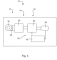
- a second embodiment of the wireless power transfer arrangement 10 is described in more detail.
- the second embodiment of the wireless power transfer arrangement 10 is only described insofar as it differs from the first embodiment.
- the wireless power transfer module 16 comprises a plurality of coil members 18 that are connected in series or in parallel. Furthermore, each coil member 18 may include a capacitor 28 between its two leads.
- the wireless power transfer module 16 comprises an AC/DC converter 30 that is electrically coupled to the coil members 18. Examples for a suitable AC/DC converter 30 are an active or passive rectifier.
- the wireless power transfer arrangement 10 comprises a plurality of electrical apparatus 20. Each electrical apparatus 20 includes an energy storage 32, e.g., a battery and a sensor 34. Each electrical apparatus 20 is connected to the AC/DC converter 30. Specifically, each energy storage 32 is connected to the AC/DC converter 30 for charging. Each sensor 34 is connected to the energy storage 32 to be supplied with electrical energy. Furthermore, it is possible that the sensor 34 has a data connection to the coil member 18 so that while the sensor 34 is powered and measuring, the detected results can be transmitted via the coil member 18.
- the sensor 34 may be a flight related sensor that is configured for measuring flight data indicative of the flight state of the aircraft.
- flight related sensors including pitot tubes, angle of attack sensors, sensors measuring the deflection of control surfaces or the extension of high-lift devices, and the like.
- the sensor 34 may be chosen as a geoinformation sensor that is configured for measuring geoinformation data that is indicative of the ground environment below the aircraft.
- sensors include laser sensors, cameras (infrared, UV ,visual), or similar kinds.
- the sensor 34 may also be chosen from a group environmental sensors that are configured for detecting the environment around the aircraft.
- Environmental sensors include radar, wind shear sensors (by means of laser Doppler effect, for example), temperature sensors, humidity sensors and pressure sensors for static air pressure.
- the senor 34 is a combined sensor that is capable of a combination of the aforementioned sensor types.
- the second wireless power transfer module 22 may also include a DC/AC converter 36 that is connected to one or more second coil members 26.
- a DC/AC converter 36 is an inverter.
- the second coil member 26 may also include a second capacitor 38 that is connected between its leads.
- the electrical connection and thus charging of the energy storage 32 functions similar to the first embodiment.
- the second wireless power transfer module 22 is brought close to the wireless power transfer module 16, specifically the coil members 18.
- the DC/AC converter 36 is supplied with direct current, for example from the power supply 24 and converts the direct current to alternating current.
- the alternating current is fed to the second coil member 26 and generates an alternating electromagnetic field.
- the alternating electromagnetic field couples to the coil members 18 which generates an alternating current in the wireless power transfer module 16.
- the alternating current is fed to the AC/DC converter 30 which converts the alternating current to a direct current that is suitable for charging the energy storage 32.
- the senor 34 transmits stored data using the wireless power transfer module 16 and the second wireless power transfer module 22.
- the data so transmitted for example flight data, geoinformation data and/or environmental data, can then be extracted for further analysis.
- the electrical apparatus 20 includes a DC/DC converter 40.
- the DC/DC converter 40 is connected to a sensor 34 that may be of the type that is very sensitive to variations in input voltage, for example.
- the electrical apparatus 20 further includes a controller 42 that is connected to the sensor 34 and receives its supply voltage as an input.
- the controller 42 is operatively coupled to the DC/DC converter 40 for controlling the output voltage.
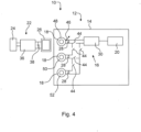
- the wireless power transfer arrangement 10 includes a plurality of switches 44 which are arranged such that the configuration of coil members 18 can be changed, i.e. whether the respective coil member 18 can supply the electrical apparatus 20 or not.
- a current sensor 46 may be arranged on a lead of a first coil member 48. If the current sensor 46 determines the current in the first coil member 48 to be below a predetermined first threshold, e.g., 3 A, then only the first coil member 48 is active to supply the electrical apparatus 20.
- a predetermined first threshold e.g. 3 A
- the switches 44 are opened and closed such that the first coil member 48 and the second coil member 50 are coupled in series and together supply the electrical apparatus 20.
- This configuration is active until a predetermined second threshold which is greater than the predetermined first threshold, e. g., 5 A, is exceeded.
- the switches 44 are opened and closed such that the first and second coil members 48, 50 are connected in series with a third coil member 52 to supply the electrical apparatus.
- any sensible number of coil members can be used in this manner.
- the aircraft component 12 is preferably configured as a passenger seat having an integrated passenger tray or other surface to which a passenger has access.
- the body portion 14, which includes the coil member 18 is preferably formed as a passenger tray that can be stowed and deployed by flipping between a vertical and horizontal position.
- the body portion 14 is operatively coupled to a switch 44. This coupling can be mechanical, for example.
- the switch 44 is electrically connected to the electrical apparatus 20, for example the energy storage 32.
- the switch 44 Upon flipping the body portion 14 from the stowed vertical position to the deployed horizontal position, the switch 44 is activated and the respective coil member 18 is energized by the energy storage 32. Now a passenger can charge his mobile device, for example, by putting it onto the body portion 14, specifically close to coil member 18. The respective zone may be marked on the body portion 14 for the users convenience.
- the invention proposes an aircraft component (12) that includes a wireless power transfer module (16).
- the wireless power transfer module (16) is integrated into a body portion (40), for example a tray.
- An electrical apparatus (20) such as an integrated energy storage (32), is electrically connected to the wireless power transfer module (16) to be charged by an external power supply (24).
Landscapes
- Engineering & Computer Science (AREA)
- Computer Networks & Wireless Communication (AREA)
- Power Engineering (AREA)
- Charge And Discharge Circuits For Batteries Or The Like (AREA)
Priority Applications (1)
| Application Number | Priority Date | Filing Date | Title |
|---|---|---|---|
| EP23315304.8A EP4503384A1 (de) | 2023-08-03 | 2023-08-03 | Flugzeugbauteil mit integriertem elektrischen system |
Applications Claiming Priority (1)
| Application Number | Priority Date | Filing Date | Title |
|---|---|---|---|
| EP23315304.8A EP4503384A1 (de) | 2023-08-03 | 2023-08-03 | Flugzeugbauteil mit integriertem elektrischen system |
Publications (1)
| Publication Number | Publication Date |
|---|---|
| EP4503384A1 true EP4503384A1 (de) | 2025-02-05 |
Family
ID=88510849
Family Applications (1)
| Application Number | Title | Priority Date | Filing Date |
|---|---|---|---|
| EP23315304.8A Pending EP4503384A1 (de) | 2023-08-03 | 2023-08-03 | Flugzeugbauteil mit integriertem elektrischen system |
Country Status (1)
| Country | Link |
|---|---|
| EP (1) | EP4503384A1 (de) |
Citations (13)
| Publication number | Priority date | Publication date | Assignee | Title |
|---|---|---|---|---|
| US6489745B1 (en) * | 2001-09-13 | 2002-12-03 | The Boeing Company | Contactless power supply |
| WO2015077239A1 (en) * | 2013-11-22 | 2015-05-28 | Johnson Controls Technology Company | System for charging and securing an electronic device in a vehicle |
| WO2016108949A1 (en) * | 2014-12-31 | 2016-07-07 | Massachusetts Institute Of Technology | Adaptive control of wireless power transfer |
| US20180301940A1 (en) * | 2017-04-12 | 2018-10-18 | Samsung Electronics Co., Ltd. | Wireless power transmitter, wireless power receiving electronic device, and method for operating the same |
| EP3142223B1 (de) * | 2015-09-11 | 2018-11-14 | Astronics Advanced Electronic Systems Corp. | Bewegliches oberflächenstromversorgungssystem |
| US20190027972A1 (en) * | 2017-07-20 | 2019-01-24 | Goodrich Control Systems | Wireless power system |
| EP3222514B1 (de) | 2016-03-21 | 2019-05-22 | Airbus Operations GmbH | Hautschicht mit energiespeicherschicht für ein flugzeug oder ein raumfahrzeug sowie verfahren zur herstellung einer energiespeicherschicht für eine hautschicht |
| EP3561909A1 (de) | 2018-04-27 | 2019-10-30 | Airbus Operations GmbH | Strukturbauteil mit einem integrierten batterieaufbau |
| US20200119591A1 (en) * | 2018-10-11 | 2020-04-16 | Searete, Llc | Dynamic rectifier circuits with multiple-order timescale feedback controls |
| WO2021178821A1 (en) * | 2020-03-05 | 2021-09-10 | Yank Technologies, Inc. | Automotive car seat wireless charging system |
| EP4040635A1 (de) | 2021-02-08 | 2022-08-10 | Airbus Operations GmbH | Strukturbauteil für ein fahrzeug und befestigungsanordnung |
| EP4051579A1 (de) | 2019-12-05 | 2022-09-07 | Airbus Operations GmbH | Leichtbaustruktur für ein fahrzeug und luftfahrzeug |
| EP4122816A1 (de) | 2021-07-21 | 2023-01-25 | Airbus Operations GmbH | Seitenwandteil einer flugzeugkabine, rumpfstruktur und flugzeug damit |
-
2023
- 2023-08-03 EP EP23315304.8A patent/EP4503384A1/de active Pending
Patent Citations (13)
| Publication number | Priority date | Publication date | Assignee | Title |
|---|---|---|---|---|
| US6489745B1 (en) * | 2001-09-13 | 2002-12-03 | The Boeing Company | Contactless power supply |
| WO2015077239A1 (en) * | 2013-11-22 | 2015-05-28 | Johnson Controls Technology Company | System for charging and securing an electronic device in a vehicle |
| WO2016108949A1 (en) * | 2014-12-31 | 2016-07-07 | Massachusetts Institute Of Technology | Adaptive control of wireless power transfer |
| EP3142223B1 (de) * | 2015-09-11 | 2018-11-14 | Astronics Advanced Electronic Systems Corp. | Bewegliches oberflächenstromversorgungssystem |
| EP3222514B1 (de) | 2016-03-21 | 2019-05-22 | Airbus Operations GmbH | Hautschicht mit energiespeicherschicht für ein flugzeug oder ein raumfahrzeug sowie verfahren zur herstellung einer energiespeicherschicht für eine hautschicht |
| US20180301940A1 (en) * | 2017-04-12 | 2018-10-18 | Samsung Electronics Co., Ltd. | Wireless power transmitter, wireless power receiving electronic device, and method for operating the same |
| US20190027972A1 (en) * | 2017-07-20 | 2019-01-24 | Goodrich Control Systems | Wireless power system |
| EP3561909A1 (de) | 2018-04-27 | 2019-10-30 | Airbus Operations GmbH | Strukturbauteil mit einem integrierten batterieaufbau |
| US20200119591A1 (en) * | 2018-10-11 | 2020-04-16 | Searete, Llc | Dynamic rectifier circuits with multiple-order timescale feedback controls |
| EP4051579A1 (de) | 2019-12-05 | 2022-09-07 | Airbus Operations GmbH | Leichtbaustruktur für ein fahrzeug und luftfahrzeug |
| WO2021178821A1 (en) * | 2020-03-05 | 2021-09-10 | Yank Technologies, Inc. | Automotive car seat wireless charging system |
| EP4040635A1 (de) | 2021-02-08 | 2022-08-10 | Airbus Operations GmbH | Strukturbauteil für ein fahrzeug und befestigungsanordnung |
| EP4122816A1 (de) | 2021-07-21 | 2023-01-25 | Airbus Operations GmbH | Seitenwandteil einer flugzeugkabine, rumpfstruktur und flugzeug damit |
Similar Documents
| Publication | Publication Date | Title |
|---|---|---|
| US11685290B2 (en) | Construction and operation of electric or hybrid aircraft | |
| Rong et al. | Critical review of recent development of wireless power transfer technology for unmanned aerial vehicles | |
| US11027838B2 (en) | In flight charging system | |
| KR101171024B1 (ko) | 비접촉 수전장치 및 그것을 구비하는 차량 | |
| EP3129286B1 (de) | Induktive energieübertragung in flugzeugsitzen | |
| US20180273158A1 (en) | Multi-Architecture Modular Unmanned Aerial System | |
| US9386638B2 (en) | Autonomous emergency light unit for an aircraft and emergency lighting system comprising such light unit | |
| US10992140B2 (en) | Electrical power distribution assembly for an aircraft | |
| JP6179688B1 (ja) | 飛行体の飛行システム、及び飛行体の飛行方法 | |
| US7649283B2 (en) | Inductive coupling method for remote powering of sensors | |
| EP2601101B1 (de) | Aufbau eines integrierten frachtladesystems | |
| US12246607B2 (en) | Electric power supply system for vehicle | |
| US20160185456A1 (en) | Power and data transmission over thin conductor for unmanned aerial vehicle | |
| KR101867424B1 (ko) | 비행 중인 드론에 무선으로 전력을 전송하는 무선충전장치 | |
| EP2896566B1 (de) | Berührungsloses Energieversorgungssystem für eine elektrische Sitzvorrichtung in einem Luftfahrzeug oder Raumfahrzeug | |
| EP4503384A1 (de) | Flugzeugbauteil mit integriertem elektrischen system | |
| CA2807268A1 (en) | System for contactless power transfer | |
| CN109774500A (zh) | 一种激光无人机有序充电系统 | |
| KR20170047029A (ko) | 무인 비행체 충전장치 | |
| CN110825150A (zh) | 一种无人机用具有配电功能的数字化电源装置 | |
| US10630420B2 (en) | Hybrid energy storage modules for directed energy systems | |
| CA2974749C (en) | Systems and methods for wireless transmitting electrical signals to an overhead stowage bin assembly of a vehicle | |
| JP2025535399A (ja) | 分散されたワイヤレス電力分配システム | |
| CN211529030U (zh) | 一种无人机用具有配电功能的数字化电源装置 | |
| CN116853027B (zh) | 一种飞机电推进系统动力电池组空中充电装置 |
Legal Events
| Date | Code | Title | Description |
|---|---|---|---|
| PUAI | Public reference made under article 153(3) epc to a published international application that has entered the european phase |
Free format text: ORIGINAL CODE: 0009012 |
|
| STAA | Information on the status of an ep patent application or granted ep patent |
Free format text: STATUS: THE APPLICATION HAS BEEN PUBLISHED |
|
| AK | Designated contracting states |
Kind code of ref document: A1 Designated state(s): AL AT BE BG CH CY CZ DE DK EE ES FI FR GB GR HR HU IE IS IT LI LT LU LV MC ME MK MT NL NO PL PT RO RS SE SI SK SM TR |
|
| STAA | Information on the status of an ep patent application or granted ep patent |
Free format text: STATUS: REQUEST FOR EXAMINATION WAS MADE |
|
| 17P | Request for examination filed |
Effective date: 20250723 |