EP4503405A1 - Dispositif d'assemblage de moteur électrique - Google Patents
Dispositif d'assemblage de moteur électrique Download PDFInfo
- Publication number
- EP4503405A1 EP4503405A1 EP23773674.9A EP23773674A EP4503405A1 EP 4503405 A1 EP4503405 A1 EP 4503405A1 EP 23773674 A EP23773674 A EP 23773674A EP 4503405 A1 EP4503405 A1 EP 4503405A1
- Authority
- EP
- European Patent Office
- Prior art keywords
- electric motor
- rotor shaft
- bearing
- assembling device
- clamping
- Prior art date
- Legal status (The legal status is an assumption and is not a legal conclusion. Google has not performed a legal analysis and makes no representation as to the accuracy of the status listed.)
- Pending
Links
Images
Classifications
-
- H—ELECTRICITY
- H02—GENERATION; CONVERSION OR DISTRIBUTION OF ELECTRIC POWER
- H02K—DYNAMO-ELECTRIC MACHINES
- H02K15/00—Processes or apparatus specially adapted for manufacturing, assembling, maintaining or repairing of dynamo-electric machines
- H02K15/14—Casings; Enclosures; Supports
- H02K15/144—Casings; Enclosures; Supports of shafts, bearings or supports therefor
-
- H—ELECTRICITY
- H02—GENERATION; CONVERSION OR DISTRIBUTION OF ELECTRIC POWER
- H02K—DYNAMO-ELECTRIC MACHINES
- H02K15/00—Processes or apparatus specially adapted for manufacturing, assembling, maintaining or repairing of dynamo-electric machines
- H02K15/40—Assembling dynamo-electric machines
-
- B—PERFORMING OPERATIONS; TRANSPORTING
- B23—MACHINE TOOLS; METAL-WORKING NOT OTHERWISE PROVIDED FOR
- B23P—METAL-WORKING NOT OTHERWISE PROVIDED FOR; COMBINED OPERATIONS; UNIVERSAL MACHINE TOOLS
- B23P19/00—Machines for simply fitting together or separating metal parts or objects, or metal and non-metal parts, whether or not involving some deformation; Tools or devices therefor so far as not provided for in other classes
- B23P19/02—Machines for simply fitting together or separating metal parts or objects, or metal and non-metal parts, whether or not involving some deformation; Tools or devices therefor so far as not provided for in other classes for connecting objects by press fit or for detaching same
-
- H—ELECTRICITY
- H02—GENERATION; CONVERSION OR DISTRIBUTION OF ELECTRIC POWER
- H02K—DYNAMO-ELECTRIC MACHINES
- H02K2215/00—Specific aspects not provided for in other groups of this subclass relating to methods or apparatus specially adapted for manufacturing, assembling, maintaining or repairing of dynamo-electric machines
Definitions
- the present disclosure relates to the field of electric motor assembling, and more particularly to an electric motor assembling device.
- an assembling manner of a bearing, a rotor shaft and a housing of an electric motor is that the bearing is firstly assembled with the rotor shaft to form a rotor assembly, and then the bearing of the rotor assembly is assembled in place with a bearing hole of the housing to complete the assembling of the electric motor.
- the present disclosure provides an electric motor assembling device.
- the present disclosure provides an electric motor assembling device, including a lifting mechanism, a pressure mechanism, a press head mechanism, an assembling station and a control mechanism.
- the pressure mechanism is located at one side of the assembling station, the lifting mechanism and the press head mechanism are located at the other side of the assembling station, and the pressure mechanism, the lifting mechanism and the press head mechanism are all electrically connected with the control mechanism.
- the pressure mechanism includes a pressure mechanism body and a pushing portion connected with the pressure mechanism body, and the pushing portion is configured to be pushed into the assembling station relative to the pressure mechanism body under the control of the control mechanism.
- the press head mechanism includes an abutting portion at a side of the press head mechanism facing the assembling station.
- the lifting mechanism includes a clamping portion at a side of the lifting mechanism facing the assembling station. The clamping portion is configured to move in a direction running away from the assembling station relative to the press head mechanism under the control of the control mechanism.
- the electric motor assembling device further includes a rotor shaft, and the rotor shaft is connected with the clamping portion.
- the lifting mechanism is arranged above the assembling station, and is configured to clamp the rotor shaft through the clamping portion, so that the clamping portion drives the rotor shaft to move in a direction approaching a bearing and to be fitted with a bearing inner ring under the control of the control mechanism.
- the abutting portion of the press head mechanism is configured to abut against a top of the bearing inner ring under the action of the control mechanism when the rotor shaft moves towards the bearing and is fitted with the bearing inner ring.
- the lifting mechanism further includes a connecting block connected with the clamping portion, and the connecting block is detachably connected with a rotor shaft of an electric motor.
- the clamping portion includes a first clamping body and a second clamping body, and one end of the first clamping body is connected with one end of the second clamping body; and the other end of the first clamping body and the other end of the second clamping body are attached to clamp the connecting block, or the other end of the first clamping body and the other end of the second clamping body are separated to release the connecting block.
- a first connecting portion is formed on the connecting block
- a second connecting portion is formed on the rotor shaft at a position corresponding to the first connecting portion
- the connecting block is connected with the rotor shaft through the fit of the first connecting portion and the second connecting portion.
- the first connecting portion is a first connecting hole
- the second connecting portion is a second connecting hole
- a fastener is arranged in the first connecting hole and the second connecting hole to realize the detachable connection between the rotor shaft and the connecting block.
- the first connecting portion is an engaging protrusion
- the second connecting portion is an engaging groove engaged and fitted with the engaging protrusion
- the connecting block is detachably connected with the rotor shaft through the fit of the engaging protrusion and the engaging groove.
- the first connecting portion includes a connecting thread formed on an outer wall of the connecting block, and the second connecting portion includes a threaded hole fitted with the connecting thread.
- the first connecting portion includes an engaging groove formed on an outer wall of the connecting block
- the second connecting portion includes an engaging block engaged with the engaging groove
- the connecting block includes a connecting head portion and a connecting rod portion located at a side of the connecting head portion adjacent to the assembling station, the connecting head portion is connected with the clamping portion, and the connecting thread is arranged on an outer wall of the connecting rod portion.
- an outer diameter of the connecting head portion is larger than an outer diameter of the connecting rod portion.
- the connecting head portion and the connecting rod portion are integrally formed.
- the abutting portion includes a first abutting portion arranged at a top of the lifting mechanism, and a second abutting portion and a third abutting portion respectively arranged at two sides of the first abutting portion.
- the first abutting portion, the second abutting portion and the third abutting portion are integrally formed.
- the second abutting portion and the third abutting portion are located at the top of the bearing inner ring and correspond to a position of the bearing inner ring, so as to abut against the top of the bearing inner ring when the rotor shaft moves towards the bearing and is fitted with the bearing inner ring.
- the present disclosure provides the electric motor assembling device, which includes the lifting mechanism, the pressure mechanism, the press head mechanism, the control mechanism and the assembling station.
- the pressure mechanism is located at one side of the assembling station, the lifting mechanism and the press head mechanism are located at the other side of the assembling station, and the pressure mechanism, the lifting mechanism and the press head mechanism are all electrically connected with the control mechanism.
- the pressure mechanism includes the pressure mechanism body and the pushing portion configured to abut against the bearing outer ring, and the pushing portion is configured to push into the assembling station relative to the pressure mechanism body under the control of the control mechanism.
- the press head mechanism includes the abutting portion at the side of the press head mechanism facing the assembling station, and the abutting portion is configured to abut against the bearing inner ring.
- the lifting mechanism includes the clamping portion at the side of the lifting mechanism facing the assembling station, and the clamping portion is configured to be connected with the rotor shaft.
- the clamping portion is configured to move in a direction running away from the assembling station relative to the press head mechanism under the control of the control mechanism. That is, when the bearing outer ring is assembled with a housing, a force can be applied to the bearing outer ring through the pushing portion of the pressure mechanism, so that the bearing is press-fitted into a bearing hole of the housing at the assembling station, and the bearing inner ring is not stressed at this time.
- the rotor shaft When the bearing inner ring is assembled with the rotor shaft, the rotor shaft can be driven by the lifting mechanism to move in the direction running away from the assembling station, so that the rotor shaft is installed in the bearing inner ring, and the bearing inner ring is abutted by the abutting portion of the press head mechanism, thus overcoming the acting force when the rotor shaft is assembled with the bearing inner ring.
- the bearing outer ring is not stressed at this time. That is, in the whole installation process, there are no opposite forces between the bearing inner ring and the bearing outer ring in an axial direction, so that the bearing can be prevented from being damaged to some extent, which otherwise will affect the service life of the bearing.
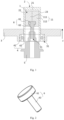
- the embodiments provide an electric motor assembling device, which includes a lifting mechanism 1, a pressure mechanism, a press head mechanism 2, a control mechanism and an assembling station.
- the pressure mechanism is located at one side of the assembling station, the lifting mechanism 1 and the press head mechanism 2 are located at the other side of the assembling station, and the pressure mechanism, the lifting mechanism 1 and the press head mechanism 2 are all electrically connected with the control mechanism.
- the pressure mechanism 2 includes a pressure mechanism body and a pushing portion for abutting against a bearing outer ring 41, and the pushing portion can be pushed into the assembling station relative to the pressure mechanism body under the control of the control mechanism.
- a side of the press head mechanism 2 facing the assembling station is provided with an abutting portion for abutting against a bearing inner ring 42.
- a side of the lifting mechanism 1 facing the assembling station is provided with a clamping portion 11 for connecting with a rotor shaft 5, and the clamping portion 11 can move in a direction running away from the assembling station relative to the press head mechanism 2 under the control of the control mechanism.
- the assembling process includes the following steps.
- a force is applied to the bearing outer ring 41 by the pushing portion of the pressure mechanism, so that a bearing 4 is press-fitted into a bearing hole 31 of the housing 3 at the assembling station, and at this time, the bearing inner ring 42 is not stressed.
- the bearing inner ring 42 When the bearing inner ring 42 is assembled with the rotor shaft 5, the rotor shaft 5 is driven by the lifting mechanism 1 to move in the direction running away from the assembling station, so that the rotor shaft 5 is installed in the bearing inner ring 42, and the bearing inner ring 42 is abutted by the abutting portion of the press head mechanism 2, thus overcoming an acting force when the rotor shaft 5 is assembled with the bearing inner ring 42.
- the bearing outer ring 41 At this time, the bearing outer ring 41 is not stressed. That is, in the whole installation process, there are no opposite forces between the bearing inner ring 42 and the bearing outer ring 41 in an axial direction, so that the bearing 4 can be prevented from being damaged to some extent, which otherwise will affect the service life of the bearing 4.
- the realization of the electric motor assembling device includes the following steps.
- the pushing portion of the pressure mechanism can abut against a top of the bearing outer ring 41 of the bearing 4 of the electric motor, and apply an axial force to the bearing outer ring 41 under the control of the control mechanism, so that the bearing 4 moves in a direction approaching the housing 3 located at the assembling station and is installed in the bearing hole 31 of the housing 3 to form a housing bearing assembly.
- the housing 3 when the housing 3 and the bearing 4 are assembled, the housing 3 can be placed at the assembling station first, the pushing portion of the pressure mechanism abuts against the bearing outer ring 41 of the bearing 4, and the bearing 4 is pressed and moved under the control of the control mechanism, so that the bearing 4 is press-fitted in the bearing hole 31 of the housing 3, to complete the assembling of the housing 3 and the bearing 4.
- the bearing 4 of the bearing housing assembly is assembled in place with the rotor shaft 5.
- the assembling structure and process of the bearing 4 of the bearing housing assembly and the rotor shaft 5 are as follows.
- the bearing housing assembly is placed as a whole at the assembling station at this time, the press head mechanism 2 is located above the assembling station, and the abutting portion of the press head mechanism is pressed and arranged on the bearing inner ring 42 of the bearing housing assembly.
- the clamping portion 11 of the lifting mechanism 1 is connected with the rotor shaft 5 of the electric motor, and clamps the rotor shaft 5 to move the rotor shaft 5 upwards under the control of the control mechanism, so as to press-fit the rotor shaft 5 in the bearing inner ring 42 of the bearing housing assembly, thus completing the assembling of the electric motor.
- the pressure mechanism can be a common press machine, etc., which is selected according to actual needs.
- the lifting mechanism 1 is arranged above the assembling station, and is used for clamping the rotor shaft 5 of the electric motor through the clamping portion 11, so that the clamping portion 11 drives the rotor shaft 5 to move in a direction approaching the bearing 4 under the control of the control mechanism and to be fitted with the bearing inner ring 42 of the bearing housing assembly.
- the abutting portion of the press head mechanism 2 is used to abut against a top of the bearing inner ring 42 under the action of the control mechanism when the rotor shaft 5 moves towards the bearing 4 and is fitted with the bearing inner ring 42.
- the lifting mechanism 1 includes a lifting body and the clamping portion 11 for clamping the rotor shaft 5.
- the control mechanism controls the clamping portion 11 to drive the rotor shaft 5 to move towards the bearing 4, and the specific direction of moving towards the bearing 4 is a Z direction shown in Fig. 1 .
- the specific structure and implementation principle of the lifting body reference can be made to the structure and principle of a lifting device in the related art, which is not specifically limited in the embodiments.
- a connecting block 6 can also be provided, and the connecting block 6 is detachably connected with the rotor shaft 5.
- the clamping portion 11 clamps the connecting block 6 to move the connecting block 6 towards the bearing 4, so as to drive the rotor shaft 5 to move towards the bearing 4 and to be assembled in the bearing inner ring 42.
- the specific connection structure between the clamping portion 11 and the connecting block 6 can be as follows.
- the clamping portion 11 includes a first clamping body 111 and a second clamping body 112, one end of the first clamping body 111 is connected with one end of the second clamping body 112, and the other end of the first clamping body 111 and the other end of the second clamping body 112 can move towards each other to clamp the connecting block 6 or move away from each other to release the connecting block 6.
- the connecting structure of the connecting block 6 and the rotor shaft 5 can be as follows. A first connecting portion is formed on the connecting block 6, a second connecting portion is formed on the rotor shaft 5 at a position corresponding to the first connecting portion, and the connecting block 6 is connected with the rotor shaft 5 through the fit of the first connecting portion and the second connecting portion, so that the connecting block 6 can be detached after the rotor shaft 5 is assembled in place.
- the first connecting portion includes a connecting thread formed on an outer wall of the connecting block
- the second connecting portion includes a threaded hole 51 fitted with the connecting thread. That is, a top end of the rotor shaft 5 is provided with an inner hole, and the inner hole specifically can be the threaded hole 51 engaged with the connecting thread.
- the connecting block 6 includes a connecting head portion 61 and a connecting rod portion 62 which can be integrally formed with the connecting head portion 61.
- An outer contour size of the connecting head portion 61 is larger than an outer diameter of the connecting rod portion 62, so that the clamping portion 11 can conveniently clamp the connecting head portion 61, and the connecting thread provided on an outer wall of the connecting rod portion 62 is engaged with the threaded hole 51.
- the first connecting portion can also be a first connecting hole and the second connecting portion is a second connecting hole, and a fastener is arranged in the first connecting hole and the second connecting hole to realize the detachable connection between the rotor shaft 5 and the connecting block 6.
- the first connecting portion can also be an engaging protrusion
- the second connecting portion is an engaging groove which is engaged and fitted with the engaging protrusion, so that the rotor shaft 5 can be detachably connected with the connecting block 6 through the fit of the engaging protrusion and the engaging groove.
- the abutting portion of the press head mechanism 2 includes a first abutting portion 21 arranged at a top of the lifting mechanism 1, and a second abutting portion 22 and a third abutting portion 23 arranged at two sides of the first abutting portion 21.
- the second abutting portion 22 and the third abutting portion 23 are located at the top of the bearing inner ring 42 and correspond to the position of the bearing inner ring 42, so as to abut against the top of the bearing inner ring 42 when the rotor shaft 5 moves towards the bearing 4 and is fitted with the bearing inner ring 42, thereby overcoming the force exerted on the bearing inner ring 42 to ensure that the bearing outer ring 41 is not stressed. That is, there are no opposite forces between the bearing inner ring 42 and the bearing outer ring 41 in the axial direction, so that the bearing 4 can be prevented from being damaged to some extent, which otherwise will affect the service life of the bearing 4.
- first abutting portion 21, the second abutting portion 22 and the third abutting portion 23 can be integrally formed, so as to save the process and improve the structural strength of the whole press head mechanism 2.
- the extension directions of the second abutting portion 22 and the third abutting portion 23 are both parallel to the direction of the rotor shaft 5 moving towards the bearing 4, so that the pressures exerted by the second abutting portion 22 and the third abutting portion 23 on the bearing inner ring 42 are axial forces, thus preventing a radial force from being generated to cause pressure and damage on the bearing outer ring 41.
- the embodiments provide the electric motor assembling device, and the assembling process of the electric motor is as follows.
- the bearing 4 is installed in the housing 3.
- a certain press-fitting force can be provided to the bearing outer ring 41 through the pressure mechanism during installation.
- only the bearing outer ring 41 is subjected to the press-fitting force and the bearing inner ring 42 is not stressed, thus ensuring that the bearing 4 itself will not be damaged in the assembling process.
- the threaded connecting block 6 is installed at the end of the rotor shaft 5.
- the clamping portion 11 grabs the connecting block 6 and lifts the rotor shaft 5 upwards, so that the rotor shaft 5 is suspended and located in a fixed position.
- stator and the rotor continue being mould-assembled until the bearing inner ring 42 is about to contact with the rotor shaft 5, the bearing inner ring 42 is pressed against by the press head mechanism 2, and the rotor shaft 5 is lifted up by the lifting mechanism 1 to be fitted with the bearing 4, so that the bearing 4 and the rotor shaft 5 are assembled in place and also the mould assembling of the stator and the rotor of the electric motor is completed. Finally, fixing bolts on the housing 3 are locked to complete the assembling of the electric motor assembly. In the whole assembling process, the bearing 4 itself can be completely avoided from being subjected to the acting force, which otherwise will case the risks of the bearing 4, such as damages to the bearing 4 and influences on the service life of the bearing 4.
Landscapes
- Engineering & Computer Science (AREA)
- Manufacturing & Machinery (AREA)
- Power Engineering (AREA)
- Manufacture Of Motors, Generators (AREA)
- Mounting Of Bearings Or Others (AREA)
Applications Claiming Priority (2)
| Application Number | Priority Date | Filing Date | Title |
|---|---|---|---|
| CN202220677290.3U CN217991608U (zh) | 2022-03-24 | 2022-03-24 | 电机装配装置 |
| PCT/CN2023/081665 WO2023179426A1 (fr) | 2022-03-24 | 2023-03-15 | Dispositif d'assemblage de moteur électrique |
Publications (2)
| Publication Number | Publication Date |
|---|---|
| EP4503405A1 true EP4503405A1 (fr) | 2025-02-05 |
| EP4503405A4 EP4503405A4 (fr) | 2025-07-09 |
Family
ID=84288018
Family Applications (1)
| Application Number | Title | Priority Date | Filing Date |
|---|---|---|---|
| EP23773674.9A Pending EP4503405A4 (fr) | 2022-03-24 | 2023-03-15 | Dispositif d'assemblage de moteur électrique |
Country Status (4)
| Country | Link |
|---|---|
| US (1) | US20250219516A1 (fr) |
| EP (1) | EP4503405A4 (fr) |
| CN (1) | CN217991608U (fr) |
| WO (1) | WO2023179426A1 (fr) |
Families Citing this family (1)
| Publication number | Priority date | Publication date | Assignee | Title |
|---|---|---|---|---|
| CN217991608U (zh) * | 2022-03-24 | 2022-12-09 | 北京车和家汽车科技有限公司 | 电机装配装置 |
Family Cites Families (7)
| Publication number | Priority date | Publication date | Assignee | Title |
|---|---|---|---|---|
| JP2005006439A (ja) * | 2003-06-12 | 2005-01-06 | Nippon Densan Corp | スピンドルモータ組立方法及び組立装置 |
| CN102412680B (zh) * | 2011-11-21 | 2013-07-31 | 福安市闽东安波电器有限公司 | 一种电机轴承装配工艺及配套工装 |
| CN203788106U (zh) * | 2014-04-01 | 2014-08-20 | 武汉轻工大学 | 电机装配装置 |
| JP2016174512A (ja) * | 2015-03-18 | 2016-09-29 | アスモ株式会社 | 回転電機及び回転電機の製造方法 |
| CN206732916U (zh) * | 2017-03-21 | 2017-12-12 | 成都华川电装有限责任公司 | 一种电机转子压装入轴承装置 |
| CN209551033U (zh) * | 2018-12-12 | 2019-10-29 | 珠海格力电器股份有限公司 | 减速器压装设备 |
| CN217991608U (zh) * | 2022-03-24 | 2022-12-09 | 北京车和家汽车科技有限公司 | 电机装配装置 |
-
2022
- 2022-03-24 CN CN202220677290.3U patent/CN217991608U/zh active Active
-
2023
- 2023-03-15 EP EP23773674.9A patent/EP4503405A4/fr active Pending
- 2023-03-15 US US18/850,359 patent/US20250219516A1/en active Pending
- 2023-03-15 WO PCT/CN2023/081665 patent/WO2023179426A1/fr not_active Ceased
Also Published As
| Publication number | Publication date |
|---|---|
| US20250219516A1 (en) | 2025-07-03 |
| WO2023179426A1 (fr) | 2023-09-28 |
| EP4503405A4 (fr) | 2025-07-09 |
| CN217991608U (zh) | 2022-12-09 |
Similar Documents
| Publication | Publication Date | Title |
|---|---|---|
| EP4503405A1 (fr) | Dispositif d'assemblage de moteur électrique | |
| KR980002906A (ko) | O링의 부착방법 및 부착장치 | |
| CN218041123U (zh) | 一种电机安装装置 | |
| CN214722039U (zh) | 一种倒挡器轴承组合压装装置 | |
| CN211449542U (zh) | 发动机皮带装配工装 | |
| CN111682716B (zh) | 辅助安装装置及辅助安装方法 | |
| CN212372063U (zh) | 一种用于齿轮组装配的定位夹具机构 | |
| CN201546643U (zh) | 可实现主动钻进的液压弹簧卡盘 | |
| CN210819344U (zh) | 一种柱塞泵用柱塞安装工具 | |
| CN108799207B (zh) | 泵体装配工艺及高效磁力驱动泵装配工艺 | |
| CN218416132U (zh) | 一种液压柱塞泵尾轴滚珠轴承便捷装配工装 | |
| CN209755985U (zh) | 自动快插快速螺纹防脱锁紧机构 | |
| CN213702615U (zh) | 压止推块夹具 | |
| CN211127500U (zh) | 一种用于电机转子铁芯的铆紧设备 | |
| JPH0984284A (ja) | ロータ用磁石の被覆方法および装置 | |
| CN212886079U (zh) | 一种多级液压油缸中缸拆装机 | |
| CN113182794B (zh) | 一种制动钳活塞和防尘罩的装配设备及其使用方法 | |
| CN220030093U (zh) | 一种衬套收口机构 | |
| CN113829273A (zh) | 一种用于齿轮组装配的定位夹具机构 | |
| CN210452582U (zh) | 一种轴承安装工具 | |
| KR100568503B1 (ko) | 보빈 홀더 | |
| CN217727769U (zh) | 一种缸体压轴承工装 | |
| JP3299113B2 (ja) | ロータ用磁石の被覆方法および装置 | |
| CN213165139U (zh) | 一种机械密封装配压板 | |
| CN223172892U (zh) | 轴承压配自动释放装置 |
Legal Events
| Date | Code | Title | Description |
|---|---|---|---|
| STAA | Information on the status of an ep patent application or granted ep patent |
Free format text: STATUS: THE INTERNATIONAL PUBLICATION HAS BEEN MADE |
|
| PUAI | Public reference made under article 153(3) epc to a published international application that has entered the european phase |
Free format text: ORIGINAL CODE: 0009012 |
|
| STAA | Information on the status of an ep patent application or granted ep patent |
Free format text: STATUS: REQUEST FOR EXAMINATION WAS MADE |
|
| 17P | Request for examination filed |
Effective date: 20240930 |
|
| AK | Designated contracting states |
Kind code of ref document: A1 Designated state(s): AL AT BE BG CH CY CZ DE DK EE ES FI FR GB GR HR HU IE IS IT LI LT LU LV MC ME MK MT NL NO PL PT RO RS SE SI SK SM TR |
|
| REG | Reference to a national code |
Ref country code: DE Ref legal event code: R079 Free format text: PREVIOUS MAIN CLASS: H02K0015000000 Ipc: H02K0015144000 |
|
| DAV | Request for validation of the european patent (deleted) | ||
| DAX | Request for extension of the european patent (deleted) | ||
| A4 | Supplementary search report drawn up and despatched |
Effective date: 20250611 |
|
| RIC1 | Information provided on ipc code assigned before grant |
Ipc: B23P 19/02 20060101ALI20250604BHEP Ipc: H02K 15/144 20250101AFI20250604BHEP |
|
| STAA | Information on the status of an ep patent application or granted ep patent |
Free format text: STATUS: THE APPLICATION IS DEEMED TO BE WITHDRAWN |