EP4503440A1 - Système et procédé de vérification de l'intégrité fonctionnelle d'un moniteur de tête de commande - Google Patents
Système et procédé de vérification de l'intégrité fonctionnelle d'un moniteur de tête de commande Download PDFInfo
- Publication number
- EP4503440A1 EP4503440A1 EP24191626.1A EP24191626A EP4503440A1 EP 4503440 A1 EP4503440 A1 EP 4503440A1 EP 24191626 A EP24191626 A EP 24191626A EP 4503440 A1 EP4503440 A1 EP 4503440A1
- Authority
- EP
- European Patent Office
- Prior art keywords
- output signal
- terminal
- mode
- line
- control head
- Prior art date
- Legal status (The legal status is an assumption and is not a legal conclusion. Google has not performed a legal analysis and makes no representation as to the accuracy of the status listed.)
- Pending
Links
Images


Classifications
-
- H—ELECTRICITY
- H03—ELECTRONIC CIRCUITRY
- H03K—PULSE TECHNIQUE
- H03K17/00—Electronic switching or gating, i.e. not by contact-making and –breaking
- H03K17/18—Modifications for indicating state of switch
-
- H—ELECTRICITY
- H03—ELECTRONIC CIRCUITRY
- H03K—PULSE TECHNIQUE
- H03K17/00—Electronic switching or gating, i.e. not by contact-making and –breaking
- H03K17/51—Electronic switching or gating, i.e. not by contact-making and –breaking characterised by the components used
- H03K17/56—Electronic switching or gating, i.e. not by contact-making and –breaking characterised by the components used by the use, as active elements, of semiconductor devices
- H03K17/687—Electronic switching or gating, i.e. not by contact-making and –breaking characterised by the components used by the use, as active elements, of semiconductor devices the devices being field-effect transistors
- H03K17/693—Switching arrangements with several input- or output-terminals, e.g. multiplexers, distributors
-
- G—PHYSICS
- G01—MEASURING; TESTING
- G01R—MEASURING ELECTRIC VARIABLES; MEASURING MAGNETIC VARIABLES
- G01R31/00—Arrangements for testing electric properties; Arrangements for locating electric faults; Arrangements for electrical testing characterised by what is being tested not provided for elsewhere
- G01R31/327—Testing of circuit interrupters, switches or circuit-breakers
- G01R31/3277—Testing of circuit interrupters, switches or circuit-breakers of low voltage devices, e.g. domestic or industrial devices, such as motor protections, relays, rotation switches
-
- G—PHYSICS
- G01—MEASURING; TESTING
- G01R—MEASURING ELECTRIC VARIABLES; MEASURING MAGNETIC VARIABLES
- G01R31/00—Arrangements for testing electric properties; Arrangements for locating electric faults; Arrangements for electrical testing characterised by what is being tested not provided for elsewhere
- G01R31/50—Testing of electric apparatus, lines, cables or components for short-circuits, continuity, leakage current or incorrect line connections
-
- H—ELECTRICITY
- H01—ELECTRIC ELEMENTS
- H01P—WAVEGUIDES; RESONATORS, LINES, OR OTHER DEVICES OF THE WAVEGUIDE TYPE
- H01P1/00—Auxiliary devices
- H01P1/10—Auxiliary devices for switching or interrupting
- H01P1/15—Auxiliary devices for switching or interrupting by semiconductor devices
-
- H—ELECTRICITY
- H03—ELECTRONIC CIRCUITRY
- H03K—PULSE TECHNIQUE
- H03K17/00—Electronic switching or gating, i.e. not by contact-making and –breaking
- H03K17/51—Electronic switching or gating, i.e. not by contact-making and –breaking characterised by the components used
- H03K17/74—Electronic switching or gating, i.e. not by contact-making and –breaking characterised by the components used by the use, as active elements, of diodes
- H03K17/76—Switching arrangements with several input- or output-terminals, e.g. multiplexers, distributors
-
- A—HUMAN NECESSITIES
- A62—LIFE-SAVING; FIRE-FIGHTING
- A62C—FIRE-FIGHTING
- A62C37/00—Control of fire-fighting equipment
- A62C37/50—Testing or indicating devices for determining the state of readiness of the equipment
Definitions
- the disclosure generally relates to control head monitors. More particularly, the disclosure relates to a system and a method for verifying operational integrity of the control head monitor.
- Control Head Monitors are typically installed onto a supervisory circuit monitored for integrity by an end of line resistor. Compromised integrity in the supervisory circuit can be differentiated from a supervisory alert as the difference between a signal indicating a broken circuit in comparison to a signal indicating a short circuit.
- CHMs Control Head Monitors
- a control head monitor including a single pole double throw (SPDT) switch having a first terminal, a second terminal, a third terminal, and a switching element.
- a load element is connected between an input line and the second terminal.
- the input line of a detection circuit is connected to the first terminal and an output line of the detection circuit is connected to the third terminal.
- the switching element is adapted, during an OFF mode, to connect the first terminal and the third terminal.
- the switching element is adapted to connect the second terminal and the third terminal to generate at least one of an output signal and an absence of an output signal.
- the load element is at least one of a resistor, a diode, an inductor, and a capacitor.
- the load element is connected on a bypassing line between the input line and the second terminal.
- a system for verifying operational integrity of a control head monitor includes the control head monitor having a single pole double throw (SPDT) switch with a first terminal, a second terminal, a third terminal, and a switching element.
- the load element is connected between an input line and the second terminal.
- the input line of a detection circuit is connected to the first terminal and an output line of the detection circuit is connected to the third terminal.
- the switching element is adapted, during an OFF mode, to connect the first terminal and the third terminal.
- the switching element is adapted, during an ON mode, to connect the second terminal and the third terminal, to generate at least one of an output signal and an absence of an output signal.
- the detection circuit includes at least one controller coupled to the input line and the output line.
- the at least one controller is adapted to receive at least one of the generated output signal and the absence of the output signal during the OFF mode and the ON mode of the control head monitor. Then, the at least one controller verifies the operational integrity of the control head monitor based on the received at least one of the output signal and the absence of the output signal during the OFF mode and the ON mode of the control head monitor.
- verifying the operational integrity of the control head monitor includes comparing at least one of the generated output signal and the absence of the output signal received during the ON mode with at least one of the generated output signal and the absence of the output signal received during the OFF mode.
- the input line, the output line, and a bypassing line through the load element is identified as in an undamaged state based on the compared at least one of the generated output signal and the absence of the output signal during the ON mode and the OFF mode.
- verifying the operational integrity of the control head monitor includes comparing at least one of the generated output signal and the absence of the output signal received during the ON mode with at least one of the generated output signal and the absence of the output signal received during the OFF mode. Next, at least one of a portion of the input line, a portion of the output line, and a portion of a bypassing line through the load element as in a damaged state based on the compared at least one of the generated output signal and the absence of the output signal during the ON mode and the OFF mode.
- the controller is adapted to generate a first notification based on the input line, the output line, and the bypassing line through the load element being identified as in the undamaged state.
- the controller generates a second notification based on at least one of a portion of the input line, a portion of the output line, and a portion of a bypassing line through the load element being identified as in the damaged state.
- the first notification and the second notification are at least one of a visual notification, an audio notification, an audio visual notification, and a haptic notification.
- the load element is at least one of a resistor, a diode, an inductor, and a capacitor.
- the load element is connected on a bypassing line between the input line and the second terminal.
- a method for verifying operational integrity of a control head monitor includes providing the control head monitor including a single pole double throw (SPDT) switch having a first terminal, a second terminal, a third terminal, and a switching element.
- SPDT single pole double throw
- a load element is connected between an input line and the second terminal.
- the input line of a detection circuit is connected to the first terminal and an output line of the detection circuit connected to the third terminal.
- the switching element is adapted, during an OFF mode, to connect the first terminal and the third terminal.
- the switching element connects the second terminal and the third terminal.
- at least one of an output signal and an absence of an output signal is generated.
- At least one controller of a detection circuit receives at least one of the generated output signal and the absence of the output signal during the OFF mode and the ON mode of the control head monitor.
- the at least one controller verifies the operational integrity of the control head monitor based on the received at least one of the output signal and the absence of the output signal during the OFF mode and the ON mode of the control head monitor.
- verifying the operational integrity of the control head monitor includes comparing at least one of the generated output signal and the absence of the output signal received during the ON mode with at least one of the generated output signal and the absence of the output signal received during the OFF mode.
- the input line, the output line, and a bypassing line through the load element is identified as in an undamaged state based on the compared at least one of the generated output signal and the absence of the output signal during the ON mode and the OFF mode.
- verifying the operational integrity of the control head monitor includes comparing at least one of the generated output signal and the absence of the output signal received during the ON mode with at least one of the generated output signal and the absence of the output signal received during the OFF mode. Next, at least one of a portion of the input line, a portion of the output line, and a portion of a bypassing line through the load element is identified as in a damaged state based on the compared at least one of the generated output signal and the absence of the output signal during the ON mode and the OFF mode.
- the controller is adapted to generate a first notification based on the input line, the output line, and the bypassing line through the load element being identified as in the undamaged state.
- the controller is adapted to generate a second notification based on at least one of a portion of the input line, a portion of the output line, and a portion of the bypassing line through the load element being identified as in the damaged state.
- the first notification and the second notification are at least one of a visual notification, an audio notification, an audio visual notification, and a haptic notification.
- FIG. 1A illustrates a schematic representation of a control head monitor 100.
- Figure 1B illustrates a circuit diagram representation of the control head monitor 100.
- the control head monitor 100 includes a single pole double throw (SPDT) switch 101 having a first terminal 101a, a second terminal 101b, a third terminal 101c, and a switching element 102.
- a load element 103 is connected between an input line 104 and the second terminal 101b. More particularly, the load element 103 is connected on a bypassing line 106 between the input line 104 and the second terminal 101b.
- the load element 103 is at least one of a resistor, a diode, an inductor, and a capacitor.
- the load element 103 may be assumed to be a resistor, a diode, an inductor, or a combination of the same; any circuit element may be used instead that, when engaged or included as part of the monitored circuit would cause the signal output to be recognizably different from either the open circuit condition or the condition when the circuit element in question is bypassed by a "short circuit" condition.
- a high or infinite resistance may be possible when the circuit is open/incomplete
- a medium or specific resistance e.g., 10ohms for a 10ohm resistor
- a low or zero resistance may be possible when the circuit has a completed path that bypasses the resistor. Therefore, if another load element can be used to produce the medium or specific resistance, which would contrast with the open or shorted conditions, then this switch arrangement would also be useful in theory as the arrangement facilitates a switching between those three possible output conditions.
- the input line 104 of a detection circuit is connected to the first terminal 101a and an output line 105 of the detection circuit is connected to the third terminal 101c.
- the switching element 102 is adapted to connect the first terminal 101a and the third terminal 101c. Since the first terminal 101a and the third terminal 101c are connected, an input signal supplied through the input line 104 is transmitted through the output line 105 as an output signal.
- the input signal may be supplied to the SPDT switch 101 to determine if internal wiring of the control head monitor 100 is unbroken or not damaged.
- an "ON mode" of the control head monitor 100 refers to a state in which the control head monitor 100 is installed and the "OFF mode" of the control head monitor 100 refers to the state in which the control head monitor is uninstalled or dismantled.
- the switching element 102 is adapted to connect the second terminal 101b and the third terminal 101c. Since the second terminal 101b and the third terminal 101c are connected, an input signal supplied through the input line 104 is transmitted to the output line 105 through the load element 103 on the bypassing line 106 as the output signal. Therefore, during both the OFF mode and the ON mode of the control head monitor 100, the input signal supplied must generate the output signal if there are no breakages or damage to the internal wires of the control head monitor 100.
- an absence of the output signal is generated.
- the output signal or the absence of the output signal may be detected to determine if a notification or alert must be generated to notify security personnel.
- FIG 2A illustrates a block diagram representation of a system 200 for verifying operational integrity of the control head monitor 100.
- the system 200 includes the control head monitor 100 having the single pole double throw (SPDT) switch 101 with the first terminal 101a, the second terminal 101b, the third terminal 101c, and the switching element 102.
- the load element 103 is connected between the input line 104 and the second terminal 101b.
- the input line 104 of the detection circuit is connected to the first terminal 101a and the output line 105 of the detection circuit is connected to the third terminal 101c as shown in Figure 1B .
- the detection circuit 201 includes at least one controller 202 coupled to the input line 104 and the output line 105.
- the at least one controller 202 is connected to the SPDT switch 101 and the load element 103 through the input line 104 and the output line 105.
- the at least one controller 202 is adapted to receive at least one of the generated output signal and the absence of the output signal during the OFF mode and the ON mode of the control head monitor 100. This means that the at least one controller 202 is adapted to receive the generated output signal or the absence of the output signal during both the OFF mode and the ON mode separately.
- the at least one controller 202 verifies the operational integrity of the control head monitor 100 based on the received at least one of the output signal and the absence of the output signal during the OFF mode and the ON mode of the control head monitor 100.
- the at least one controller 202 determines the operational integrity as being compromised. Alternatively, if the output signal is generated for both the OFF mode and the ON mode separately, then the at least one controller 202 verifies the operational integrity of the control head monitor 100.
- the term "operational integrity" refers to a normal functioning or intended state of functioning of the control head monitor 100 disclosed herein. With prolonged use, over the years, the individual components, such as the internal wires, the supply lines, terminals, etc., are prone to wear or damage. This prevents the control head monitor 100 from functioning as intended or designed. Consequently, the operational integrity of the system 200 is compromised. Therefore, periodic inspection to ascertain the operational integrity or system readiness is desirable.
- the term "at least one controller 202" may be construed to encompass one or a combination of microprocessors, suitable logic, circuits, printed circuit boards (PCB), audio interfaces, visual interfaces, haptic interfaces, or the like.
- the at least one controller 202 may include, but are not limited to a microcontroller, a Reduced Instruction Set Computing (RISC) processor, an Application-Specific Integrated Circuit (ASIC) processor, a Complex Instruction Set Computing (CISC) processor, a central processing unit (CPU), a graphics processing unit (GPU), a state machine, and/or other processing units or circuits.
- RISC Reduced Instruction Set Computing
- ASIC Application-Specific Integrated Circuit
- CISC Complex Instruction Set Computing
- CPU central processing unit
- GPU graphics processing unit
- state machine and/or other processing units or circuits.
- the at least one controller 202 may also comprise suitable logic, circuits, interfaces, and/or code that may be configured to execute a set of instructions stored in a memory unit.
- the memory unit may include, but is not limited to, Electrically Erasable Programmable Read-only Memory (EEPROM), Random Access Memory (RAM), Read Only Memory (ROM), Hard Disk Drive (HDD), Flash memory, Solid-State Drive (SSD), and/or CPU cache memory.
- EEPROM Electrically Erasable Programmable Read-only Memory
- RAM Random Access Memory
- ROM Read Only Memory
- HDD Hard Disk Drive
- Flash memory Solid-State Drive
- SSD Solid-State Drive
- the at least one controller 202 may receive power from a suitably coupled power source.
- the suitably coupled power source may be electrically coupled to the at least one controller 202 for supplying electrical power.
- the power source may be, for example, a battery, such as a rechargeable battery or a non-rechargeable battery.
- suitable batteries include, for example, a lithium battery (such as a lithium-ion battery), a nickel battery (such as a nickel-cadmium battery), and an alkaline battery.
- Figure 2B illustrates a set of sample output signals generated by the system 200 shown in Figure 2A for verifying operational integrity of the control head monitor 100.
- the step of verifying the operational integrity of the control head monitor 100 includes firstly, comparing at least one of the generated output signal or the absence of the output signal received during the ON mode with at least one of the generated output signal or the absence of the output signal received during the OFF mode.
- the input line (104), the output line (105), and the bypassing line (106) through the load element (103) are identified as in an undamaged state based on the compared at least one of the generated output signal and the absence of the output signal during the ON mode and the OFF mode.
- the controller 202 is adapted to generate a first notification based on the input line 104, the output line 105, and the bypassing line 106 through the load element 103 being identified as in the undamaged state.
- the first notification may be at least one of a visual notification, an audio notification, an audio visual notification, and a haptic notification.
- the first notification may be visual notification such as "SYSTEM READY", "SYSTEM OK", etc.
- the step of verifying the operational integrity of the control head monitor 100 may include firstly, comparing at least one of the generated output signal or the absence of the output signal received during the ON mode with at least one of the generated output signal or the absence of the output signal received during the OFF mode. Next, at least one of a portion of the input line 104, a portion the output line 105, and/or a portion of the bypassing line 106 through the load element 103 are identified as in a damaged state based on the compared at least one of the generated output signal and the absence of the output signal during the ON mode and the OFF mode.
- the output signal is absent or undetected by the detection circuit 201 at the output line 105 to be identified as in the damaged state. If the output signal is absent during either the ON mode and/or the OFF mode of the control head monitor 100, at least a portion of the input line 104, a portion of the output line 105, and/or a portion of the bypassing line 106 may be identified as in the damaged state.
- the controller 202 is adapted to generate a second notification based on at least one of a portion of the input line 104, a portion of the output line 105, and a portion of the bypassing line 106 through the load element 103 being identified as in the damaged state.
- the second notification may be at least one of a visual notification, an audio notification, an audio visual notification, and a haptic notification.
- the second notification may be visual notification such as "SYSTEM MALFUNCTION”, “TROUBLE”, “ALERT”, “TROUBLE”, “SUPERVISORY ALERT”, etc.
- the system 200 is also adapted to identify specific portions (15, 16, 17, 18, 19, 20) of the input line 104, specific portions (1, 2, 3, 4, 5) of the output line 105, and/or specific portions (6, 7, 8, 9, 10, 11, 12, 13, 14) of the bypassing line 106 as being in the damaged state.
- This is exemplarily illustrated by a sample table 203.
- Column 203a of the table 203 represents the second notification during the ON mode and Column 203b represents the second notification during the OFF mode.
- the controller 202 may determine the specific portions (15, 16, 17, 18, 19, 20) of the input line 104, the specific portions (1, 2, 3, 4, 5) of the output line 105, and/or the specific portions (6, 7, 8, 9, 10, 11, 12, 13, 14) of the bypassing line 106 as being in the damaged state.
- the second notification "TROUBLE” is displayed during both the ON mode and the OFF mode.
- an inspection or maintenance personnel can quickly identify that at least one of the specific portions (1, 2, 3, 4, 5) are damaged. This features ensures quick identification and solution of the problem.
- "SUPERVISORY” alert may be generated when the panel sees a short circuit which does not have the specified resistance (resistance is closer to zero), while “TROUBLE” alert may be generated when the loop is broken (resistance is effectively infinite). This features ensures quick identification and solution of the problem.
- the second notification "TROUBLE” is generated during the OFF mode.
- the inspection or maintenance personnel can quickly identify that at least one of the specific portions (17, 18, 19, 20) is damaged.
- the inspection or maintenance personnel can quickly identify that at least one of the specific portions (15, 16) is damaged.
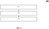
- Figure 3 illustrates a flowchart indicating a method 300 for verifying operational integrity of the control head monitor.
- FIG. 3 illustrates a flowchart indicating a method 300 for verifying operational integrity of the control head monitor.
- the method 300 for verifying operational integrity of the control head monitor 100 includes, at Step 301, providing the control head monitor 100 including the single pole double throw switch (SPDT) 101 having the first terminal 101a, the second terminal 101b, the third terminal 101c, and the switching element 102, the load element 103 is connected between the input line 104 and the second terminal 101b.
- the input line 104 of the detection circuit is connected to the first terminal 101a and the output line 105 of the detection circuit is connected to the third terminal 101c.
- the switching element 102 is adapted, during an OFF mode, to connect the first terminal 101a and the third terminal 101c.
- the switching element 102 is adapted, during an ON mode, to connect the second terminal 101b and the third terminal 101c, to generate at least one of the output signal and the absence of the output signal.
- the at least one controller 202 of the detection circuit 201 receives at least one of the generated output signal and the absence of the output signal during the OFF mode and the ON mode of the control head monitor 100.
- the at least one controller 202 verifies the operational integrity of the control head monitor 100 based on the received at least one of the output signal and the absence of the output signal during the OFF mode and the ON mode of the control head monitor 100.
- control head monitor 100 utilizes the SPDT switch 101, complex modification of existing control head monitors 100 or existing systems are eliminated.
- the system 200 allows easy monitoring and diagnosis of potential damage or breakages of the internal wires or wiring of the control head monitor 100.
- the controller 202 may determine the specific portions (15, 16, 17, 18, 19, 20) of the input line 104, the specific portions (1, 2, 3, 4, 5) of the output line 105, and/or the specific portions (6, 7, 8, 9, 10, 11, 12, 13, 14) of the bypassing line 106 as being in the damaged state. This allows maintenance or inspecting personnel to quickly identify the problem associated with the control head monitor 100 thereby ensuring quick resolution and reduced downtime.
Landscapes
- Physics & Mathematics (AREA)
- General Physics & Mathematics (AREA)
- Testing Of Short-Circuits, Discontinuities, Leakage, Or Incorrect Line Connections (AREA)
- Testing And Monitoring For Control Systems (AREA)
Applications Claiming Priority (1)
| Application Number | Priority Date | Filing Date | Title |
|---|---|---|---|
| US202363517889P | 2023-08-04 | 2023-08-04 |
Publications (1)
| Publication Number | Publication Date |
|---|---|
| EP4503440A1 true EP4503440A1 (fr) | 2025-02-05 |
Family
ID=92142201
Family Applications (1)
| Application Number | Title | Priority Date | Filing Date |
|---|---|---|---|
| EP24191626.1A Pending EP4503440A1 (fr) | 2023-08-04 | 2024-07-30 | Système et procédé de vérification de l'intégrité fonctionnelle d'un moniteur de tête de commande |
Country Status (2)
| Country | Link |
|---|---|
| EP (1) | EP4503440A1 (fr) |
| CN (1) | CN119438743A (fr) |
Citations (4)
| Publication number | Priority date | Publication date | Assignee | Title |
|---|---|---|---|---|
| WO2016196104A1 (fr) * | 2015-06-04 | 2016-12-08 | Utc Fire & Security Corporation | Dispositif monté à l'extérieur, permettant de surveiller un système d'extinction d'incendie |
| WO2017153847A1 (fr) * | 2016-03-11 | 2017-09-14 | Analog Devices Global | Plateforme matérielle configurable servant à des fins de mesure ou de commande |
| WO2019237056A1 (fr) * | 2018-06-08 | 2019-12-12 | Tyco Fire Products Lp | Système de surveillance de cartouche |
| WO2020112216A1 (fr) * | 2018-11-30 | 2020-06-04 | Carrier Corporation | Surveillance à distance d'un système d'extinction d'incendie |
-
2024
- 2024-07-30 EP EP24191626.1A patent/EP4503440A1/fr active Pending
- 2024-08-02 CN CN202411054177.XA patent/CN119438743A/zh active Pending
Patent Citations (4)
| Publication number | Priority date | Publication date | Assignee | Title |
|---|---|---|---|---|
| WO2016196104A1 (fr) * | 2015-06-04 | 2016-12-08 | Utc Fire & Security Corporation | Dispositif monté à l'extérieur, permettant de surveiller un système d'extinction d'incendie |
| WO2017153847A1 (fr) * | 2016-03-11 | 2017-09-14 | Analog Devices Global | Plateforme matérielle configurable servant à des fins de mesure ou de commande |
| WO2019237056A1 (fr) * | 2018-06-08 | 2019-12-12 | Tyco Fire Products Lp | Système de surveillance de cartouche |
| WO2020112216A1 (fr) * | 2018-11-30 | 2020-06-04 | Carrier Corporation | Surveillance à distance d'un système d'extinction d'incendie |
Also Published As
| Publication number | Publication date |
|---|---|
| US20250047280A1 (en) | 2025-02-06 |
| CN119438743A (zh) | 2025-02-14 |
Similar Documents
| Publication | Publication Date | Title |
|---|---|---|
| KR940021405A (ko) | 엘리베이터의 이상 해석 데이터 수집장치 | |
| JP6046404B2 (ja) | 表示装置 | |
| JPH09230929A (ja) | 車載コントローラの故障診断方法及び装置 | |
| CN102457275B (zh) | 电子控制装置 | |
| US20220406103A1 (en) | Fault diagnosis device, fault diagnosis system, fault diagnosis method, and fault diagnosis program | |
| KR20210098124A (ko) | 전동화 자동차 교육용 고장 진단 시스템 | |
| KR20130120330A (ko) | 자동차 고장 진단 시스템 | |
| EP4503440A1 (fr) | Système et procédé de vérification de l'intégrité fonctionnelle d'un moniteur de tête de commande | |
| US12615046B2 (en) | System and method for verifying operational integrity of a control head monitor | |
| JP3965772B2 (ja) | 車両用故障診断装置 | |
| US10032356B1 (en) | Display card protection circuit monitoring structure | |
| CN112988445A (zh) | 一种计算机板卡故障诊断方法、系统及计算机板卡 | |
| US7903539B2 (en) | Electronic control unit | |
| KR101938756B1 (ko) | 전원 공급 상태 진단 및 표시 기능을 구비한 poe 패치 패널 | |
| US9501347B2 (en) | Documentation of faults in a fault memory of a motor vehicle | |
| US12261868B2 (en) | On-vehicle device and log management method | |
| JPH1019662A (ja) | 自己診断装置 | |
| KR101669401B1 (ko) | 검사기기 사전 경보시스템 | |
| US20020194537A1 (en) | Diagnosis of fault conditions in embedded systems | |
| JP2010002188A (ja) | 半導体試験装置 | |
| KR0136225B1 (ko) | 건설중장비 제어기의 이상진단장치 및 진단방법 | |
| KR19980075069A (ko) | 차량 상태 음성 경고 장치 | |
| US20250189590A1 (en) | Method for Determining a Thermal Runaway of an Electric Energy Storage Unit of an at Least Partially Electrically Operated Motor Vehicle, Computer Program Product, and Electronic Computing Device | |
| JP2019139558A (ja) | 工作機械の制御装置 | |
| US11676477B2 (en) | Fire alarm system |
Legal Events
| Date | Code | Title | Description |
|---|---|---|---|
| PUAI | Public reference made under article 153(3) epc to a published international application that has entered the european phase |
Free format text: ORIGINAL CODE: 0009012 |
|
| STAA | Information on the status of an ep patent application or granted ep patent |
Free format text: STATUS: THE APPLICATION HAS BEEN PUBLISHED |
|
| AK | Designated contracting states |
Kind code of ref document: A1 Designated state(s): AL AT BE BG CH CY CZ DE DK EE ES FI FR GB GR HR HU IE IS IT LI LT LU LV MC ME MK MT NL NO PL PT RO RS SE SI SK SM TR |
|
| P01 | Opt-out of the competence of the unified patent court (upc) registered |
Free format text: CASE NUMBER: APP_30619/2025 Effective date: 20250626 |
|
| STAA | Information on the status of an ep patent application or granted ep patent |
Free format text: STATUS: REQUEST FOR EXAMINATION WAS MADE |
|
| 17P | Request for examination filed |
Effective date: 20250801 |