EP4505069B1 - Ensemble piston axial hydraulique et procédé de commande associé - Google Patents
Ensemble piston axial hydraulique et procédé de commande associé Download PDFInfo
- Publication number
- EP4505069B1 EP4505069B1 EP23705643.7A EP23705643A EP4505069B1 EP 4505069 B1 EP4505069 B1 EP 4505069B1 EP 23705643 A EP23705643 A EP 23705643A EP 4505069 B1 EP4505069 B1 EP 4505069B1
- Authority
- EP
- European Patent Office
- Prior art keywords
- pressure
- hydraulic
- port
- control port
- odc
- Prior art date
- Legal status (The legal status is an assumption and is not a legal conclusion. Google has not performed a legal analysis and makes no representation as to the accuracy of the status listed.)
- Active
Links
Images





Classifications
-
- F—MECHANICAL ENGINEERING; LIGHTING; HEATING; WEAPONS; BLASTING
- F04—POSITIVE - DISPLACEMENT MACHINES FOR LIQUIDS; PUMPS FOR LIQUIDS OR ELASTIC FLUIDS
- F04B—POSITIVE-DISPLACEMENT MACHINES FOR LIQUIDS; PUMPS
- F04B1/00—Multi-cylinder machines or pumps characterised by number or arrangement of cylinders
- F04B1/12—Multi-cylinder machines or pumps characterised by number or arrangement of cylinders having cylinder axes coaxial with, or parallel or inclined to, main shaft axis
- F04B1/26—Control
- F04B1/30—Control of machines or pumps with rotary cylinder blocks
- F04B1/32—Control of machines or pumps with rotary cylinder blocks by varying the relative positions of a swash plate and a cylinder block
- F04B1/324—Control of machines or pumps with rotary cylinder blocks by varying the relative positions of a swash plate and a cylinder block by changing the inclination of the swash plate
-
- F—MECHANICAL ENGINEERING; LIGHTING; HEATING; WEAPONS; BLASTING
- F04—POSITIVE - DISPLACEMENT MACHINES FOR LIQUIDS; PUMPS FOR LIQUIDS OR ELASTIC FLUIDS
- F04B—POSITIVE-DISPLACEMENT MACHINES FOR LIQUIDS; PUMPS
- F04B1/00—Multi-cylinder machines or pumps characterised by number or arrangement of cylinders
- F04B1/12—Multi-cylinder machines or pumps characterised by number or arrangement of cylinders having cylinder axes coaxial with, or parallel or inclined to, main shaft axis
- F04B1/20—Multi-cylinder machines or pumps characterised by number or arrangement of cylinders having cylinder axes coaxial with, or parallel or inclined to, main shaft axis having rotary cylinder block
- F04B1/2014—Details or component parts
- F04B1/2021—Details or component parts characterised by the contact area between cylinder barrel and valve plate
-
- F—MECHANICAL ENGINEERING; LIGHTING; HEATING; WEAPONS; BLASTING
- F04—POSITIVE - DISPLACEMENT MACHINES FOR LIQUIDS; PUMPS FOR LIQUIDS OR ELASTIC FLUIDS
- F04B—POSITIVE-DISPLACEMENT MACHINES FOR LIQUIDS; PUMPS
- F04B1/00—Multi-cylinder machines or pumps characterised by number or arrangement of cylinders
- F04B1/12—Multi-cylinder machines or pumps characterised by number or arrangement of cylinders having cylinder axes coaxial with, or parallel or inclined to, main shaft axis
- F04B1/26—Control
- F04B1/30—Control of machines or pumps with rotary cylinder blocks
-
- F—MECHANICAL ENGINEERING; LIGHTING; HEATING; WEAPONS; BLASTING
- F04—POSITIVE - DISPLACEMENT MACHINES FOR LIQUIDS; PUMPS FOR LIQUIDS OR ELASTIC FLUIDS
- F04B—POSITIVE-DISPLACEMENT MACHINES FOR LIQUIDS; PUMPS
- F04B49/00—Control, e.g. of pump delivery, or pump pressure of, or safety measures for, machines, pumps, or pumping installations, not otherwise provided for, or of interest apart from, groups F04B1/00 - F04B47/00
- F04B49/002—Hydraulic systems to change the pump delivery
Definitions
- the present invention relates to hydraulic axial piston units and a method for controlling hydraulic axial piston units. More specifically, the invention relates to hydraulic axial piston units of the swashplate type as well as hydraulic axial piston units of the bent-axis type of construction. The invention also relates to a method for controlling both types of hydraulic axial piston units.
- the hydraulic axial piston units to which the invention refers to can be used in open hydraulic circuits as well as in closed hydraulic circuits and can comprise a fixed displacement volume or a variable displacement volume.
- Hydraulic axial piston units of the swashplate or the bent-axis type of construction are widely known in the state of the art and are used as fixed or variable displacements units. All of them can be operated in pumping or motoring mode.
- the displacement volume of the hydraulic axial piston units can be set/controlled by means of setting/changing the tilt angle of a displacement element, i.e. the swashplate or the yoke.
- a hydraulic axial piston units comprise a rotational group.
- one of the inlet port or the outlet port is serving as a high pressure port and the respective other port serves as a low pressure port. It depends on the operational mode of the hydraulic unit and the hydraulic flow direction, which port serves as high pressure port and which port serves as low pressure port.
- hydraulic or electronic control units are used for setting the tilt angle of a displacement element of a hydraulic axial piston unit.
- these control units frequently control the movement of servo pistons in servo units by selectively directing hydraulic pressure into pressure chambers of the servo unit by means of shifting a control spool.
- These control and servo arrangements are complex due to the high level of demand in manufacturing and operation precision and are prone to errors. Thus, they are costly in manufacturing and installation work.
- control and servo units known in the art, and - due their amount of parts - are bulky and space consuming so that the overall size of hydraulic axial piston units is increased.
- the known controls of hydraulic axial piston units are developed for specific applications and require a specific adaptation of the control parts for each and every application, like specific valve plates and/or valve segments as well as specifically adapted servo and control spools and springs, which all require narrow tolerances.
- the components of the displacement control units are exposed to wear and therefore require continuous maintenance or replacement.
- these specific components are not suitable to be changed on the fly, i.e. once installed they cannot be adapted to individual load situations, and moreover they often cannot be used in different hydraulic axial piston units of different volumetric size/ cubic capacity.
- the hydraulic axial piston unit according to the invention shall be less costly and shall require less construction space compared to the solutions known in the art.
- the control system for a hydraulic axial piston unit according to invention is intended to be adaptable to different hydraulic axial piston units, even on-the-fly, i.e. without having to disassemble the hydraulic axial piston unit.
- the objective is solved by a hydraulic axial piston unit according to Claim 1 and a method for controlling the displacement volume of a hydraulic rotation group according to Claim 20.
- a hydraulic axial piston unit comprises a rotating group whose displacement volume is set by means of a displacement element.
- the rotating group comprises a rotatable cylinder block with cylinder bores in which working pistons are mounted reciprocally moveable.
- the pistons When the cylinder block rotates and the displacement element is inclined with respect to the rotational axis of the cylinder block, the pistons perform a fore-and-aft movement in the corresponding cylinder bores.
- the piston changes its direction of motion two times.
- the working piston changes its direction of motion from travelling towards fluid exchange opening of the cylinder bore to travelling away from the fluid exchange opening of the cylinder bore.
- the inner dead centre is the position in which the working piston is closest to the fluid exchange openings of the cylinder bore, that is, it is inserted furthest into the cylinder bore, and the fluid volume in the cylinder bore is minimum.
- ODC outer dead centre
- the movement of the working piston is changed from travelling away from the fluid exchange opening of the cylinder bore to a movement towards the fluid exchange openings of the cylinder bore.
- the working piston is at the position most distant from the fluid exchange opening of the corresponding cylinder bore, i.e. where the working piston is furthest extracted out of the cylinder bore, and the fluid volume in cylinder bore is the largest the set tilt angle permits.
- the adjustable longitudinal position of the inner dead centre and of the outer dead centre of the working pistons i.e., the position seen along the rotational axis of the rotational group, depends on the inclination angle/tilt angle of the displacement element.
- the angular position of the inner and the outer dead centre is set fixedly by the rotational group design as long as the orientation and the position of the tilt axis of the displacement element is not changed, i.e. independent of the tilt angle of the displacement element.
- the hydraulic axial piston unit further comprises a valve segment with a kidney-shaped first pressure port and a kidney-shaped second pressure port. Hydraulic fluid can be conducted to and drained from the cylinder bores when a cylinder bore overlaps with the first or the second pressure port.
- an IDC control port and an ODC control port are located on the valve segment in circumferential direction between the respective circumferential ends of the kidney-shaped first pressure port and the kidney-shaped second pressure port.
- the pressure and the control ports are arranged alternately in circumferential direction, e.g. ODC control port, first pressure port, IDC control port, second pressure port.
- the IDC and ODC control ports are arranged on the valve segment in such a way that a cylinder bore can be fluidly connected to the IDC control port or the ODC control port when the associated working piston is at or close to its inner dead centre (IDC) or is at or close to its outer dead centre (ODC), respectively.
- IDC inner dead centre
- ODC outer dead centre
- the circumferential position of the IDC and the ODC of the working pistons is constant.
- the circumferential position of the IDC control port on the valve segment is always at or near the IDC of the working pistons and analogously the ODC control port on the valve segment is always at or near the circumferential position of the ODC of the working pistons.
- the circumferential distance of the IDC control port to the first and second pressure ports and analogously the circumferential distance of the ODC control port to the first and second pressure ports is smaller than the circumferential extension of the cylinder bores or their openings towards the valve segment.
- a cylinder bore is simultaneously in contact with the IDC or with the ODC control port, when it stops overlapping with the first or second pressure ports, e.g. in case of a hydraulic axial piston pump, overpressure or excess hydraulic fluid can be drained via the IDC control port or cavitation can be avoided by additional hydraulic fluid supply via the ODC control port.
- cavitation may occur at the ODC of the working piston, therefore, in this case, hydraulic fluid supply over the ODC control port can avoid or at least can reduce the cavitation effect.
- pressure peaks and a disadvantageous pressure distribution over the valve segment is avoided as well as elongation grooves (fishtails) mentioned before.
- a first bypass line and a second bypass line are provided each connecting one of the control ports, i.e. the IDC control port or the ODC control port, with one of the first or the second pressure port or with a pressure compensation chamber.
- an adjustable orifice is arranged capable of continuously and variably opening and closing the first bypass line in order to enable an adjustable fluid flow connection between the connected pressure port and the passing cylinder bore via the first bypass line and the allocated control port.
- a second bypass line is connected to the respective other control port.
- the orifice in the first bypass line can be provided as an additional part, e.g. in form of a flow valve or similar, especially preferred an adjustable flow opening.
- non-adjustable orifices can be formed also integrally with the first and/or second bypass line, in which they are arranged.
- the tilt angle of the displacement element of the hydraulic unit can be adjusted and set.
- the magnitude of the opening of the orifice(s) can e.g. be controlled by an electronic control unit. Thereby, it is not required that hydraulic fluid is injected into a passing cylinder bore in a short time interval, e.g. in the range of milliseconds. Quite to the contrary, static pressure is used to control and set the pressure profile, which is encountered by a cylinder bore, when passing one of the control ports.
- the tilt angle of the displacement element and the opening of an adjustable orifice do not regularly change with a high frequency.
- the adjustable orifice can be a rotary spool valve or a linear spool valve which is accommodated in a valve bore.
- the rotary or linear spool of the valve can comprise recesses or openings which overlap with channels in the valve bore, i.e. valve ports, wherein the magnitude of overlapping can be continuously adjusted by rotating the rotary spool or by longitudinal moving the linear spool.
- the orifice can be a linear operating valve/orifice, a rotary valve/orifice, or a flow valve. Flow valves are generally less costly than linear or rotationally operating orifices.
- a person skilled in the relevant art will find plenty of solutions how to provide an adjustable orifice, i.e. an orifice whose magnitude of opening is adjustable.
- the shape of the control ports is relevant for achieving a good controllability of the tilt angle of the displacement element.
- a round/circular shape of the control ports requires low manufacturing effort and therefore represents a solution causing low costs.
- the shape of the control ports can also be adapted to the shape of the opening of the cylinder bores.
- the control ports can comprise any desired shape.
- the control ports can show an elongated shape in circumferential direction of the valve segment with a radial extension that matches the radial extension of the cylinder bores. This design provides an increased overlap between the opening of the cylinder bore and the control port.
- the control port can also comprise a kidney shape, wherein the longer side of the kidney preferably extends in circumferential direction.
- the control port can also comprise an ellipse shape, a triangle shape, or any other shape, wherein even the manufacturing direction must not coincide with rotational axis of the valve segment.
- the IDC control port and/or the ODC control port can be located on the valve segment exactly at that rotational position at which the working pistons are at their inner dead centre (IDC) and/or their outer dead centre (ODC), respectively.
- This arrangement can for example be preferable for hydraulic units, especially hydraulic motors, which are operated with changing directions of fluid flow, but whose displacement element can be tilted only in one direction.
- the algebraic sign of the tilt angle does not change, the rotational position of the inner dead centre and the outer dead centre remains the same, even if the direction of fluid flow is changed.
- the direction of the fluid flow is inverted and the direction of tilt remains constant, the direction of rotation of a hydraulic motor is inverted.
- the shuttle valve is capable of conducting the higher system pressure from the first or second pressure ports to the IDC control port, or to the ODC control port; or to the control valve.
- the IDC control port is connected to a higher pressure, e.g. inlet pressure
- the ODC control port can be connected in this case to a lower pressure, e.g. outlet pressure or to a hydraulic reservoir.
- the one-directional tilt angle of the displacement element can be controlled independently of the direction of rotation of the hydraulic unit, here exemplarily a hydraulic motor.
- the opening of an orifice in the second bypass line which could - for example - be connected to the ODC control port, could be adjusted in order to influence the tilt angle of the hydraulic unit.
- the opening of an orifice in the first bypass line connected to the IDC control port could be adjusted and therewith the pressure level present at the IDC control port can be controlled. This influences the profile of pressures acting on a working piston during one revolution around the cylinder block axis, at least until the working pistons reaches the other control port.
- the radial position of the control ports can deviate from the pitch diameter defined by the circumferential extension of the first and second pressure ports. In other words, the radial distance of the control ports to the rotational axis of the hydraulic unit must not be equal to the pitch radius of the pressure ports.
- a method for controlling the displacement volume of a hydraulic rotating group driving or being driven by a driving shaft comprises a displacement element which can be tilted in order to adjust the displacement volume of the rotating group.
- the rotating group comprises a rotatable cylinder block with cylinder bores in which working pistons are mounted reciprocally moveable, and a valve segment with a kidney-shaped first pressure port and with a kidney-shaped second pressure port.
- An IDC control port and an ODC control port are located on the valve segment in circumferential direction between the respective circumferential ends of the first pressure port and the second pressure port.
- reactio reactio
- the supporting force influences the balance of forces and torques present at the displacement element.
- supply or drain of hydraulic fluid is done with the pressure level of the subsequent/ next coming pressure port - seen in direction of rotation of the cylinder block or the rotating group.
- the pressure level at the IDC is changing from the high system pressure to the low system pressure such that according to the invention, the IDC control port located between the two pressure kidneys at, or nearby IDC is preferably connected via a bypass line to the low system pressure kidney.
- an adjustable orifice is arranged in this bypass line, in particular for hydraulic pumps operable with positive as well as negative tilt angles, as in this case the IDC changes with the ODC by tilting the displacement element over zero, and vice versa, such that the control port can be the IDC control port as well as the ODC control port.
- the method according to the invention may further comprise the step of processing a command of a control unit or an operator by means of an electronic control unit (ECU).
- the electronic control unit can comprise a microcontroller for adjusting the size of the openings of the orifices in the first bypass line and/or in the second bypass line, in order to adapt/control the pressure in the cylinder bores for controlling the displacement volume of the hydraulic axial piston unit.
- any of the adjustable orifices can be controlled by the electronic control unit, regardless of whether the bypass line in which the adjustable orifice is arranged, connects one of the control ports with one of the pressure ports, or with a hydraulic reservoir, or with a pressure compensation chamber or closed cavity.
- the method may further comprise the step of continuously monitoring the operational parameters of the hydraulic axial piston unit in order to smoothen pressure transitions between the kidney-shaped first and second pressure ports and vice versa, and/or for controlling the pressure level in the cylinder bores and thus the pressure profile in the cylinder bores on its way around the rotational axis of the hydraulic axial piston unit, i.e. the course of pressure in dependency of the rotational angle of the cylinder block.
- the method according to the invention further enables adjusting the tilt angle of the displacement element by controlling the pressure level present at the control ports by means of opening and closing the opening size of an adjustable orifice.
- measured operational parameters of the hydraulic unit can be processed by the electronic control unit.
- FIG. 1 shows an exemplary design of a first embodiment of a hydraulic axial piston unit according to the invention.
- the hydraulic pump comprises a displacement element 4 which can be tilted with respect to a tilt axis 9 in order to adjust the displacement volume of a rotating group 2 of the hydraulic unit.
- the rotating group 2 comprises a cylinder block 3 rotatable around a rotational axis 13, having cylinder bores 5 in which working pistons 6 are mounted reciprocally moveable between an outer dead centre (ODC) and an inner dead centre (IDC).
- ODC outer dead centre
- IDDC inner dead centre
- the hydraulic unit is operated in an open hydraulic circuit, for example.
- the first pressure port 21 is connected to a low system pressure, e.g. to the hydraulic reservoir 100.
- the second pressure port 22 is connected to high pressure line.
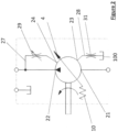
- An orifice 29 with a variably adjustable opening size is arranged in the first bypass line 27 for adjusting the fluid flow in the bypass line 27 and therewith the pressure level at the ODC control port 24.
- opening of the adjustable orifice 29 increases the flow and pressure at the ODC control port 24.
- the second bypass line 28 comprises an orifice 31, whose opening size in this embodiment is not adjustable.
- the flow resistance in the second bypass line 28 is not adjustable.
- the hydraulic unit further comprises a return mechanism 10 that forces the displacement element 4 of the hydraulic unit back into its initial position, when the displacement element 4 is titled out of this initial position.
- the initial position of the displacement element 4 can be at a tilt angle of zero degrees, e.g.
- the displacement element 4 can be initially tilted towards a non-zero tilt angle.
- the rotational axis 12 of the displacement element 4 respectively the rotational axis 12 of the sliding surface for the guiding shoes on the displacement element 4
- the displacement element 4 of the hydraulic unit can be biased to a non-zero displacement angle by means of an elastic force, e.g. provided by a spring.
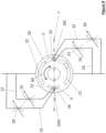
- FIG 3 schematically shows the valve segment 20 of the first embodiment of a hydraulic axial piston unit according to the invention.
- the valve segment 20 comprises a first pressure port 21 and a second pressure port 22. Both pressure ports show a kidney-shape.
- the first pressure port 21, - the suction port of the hydraulic unit in the example of the first embodiment according to Figures 2 and 3 - is connected to a hydraulic reservoir 100.
- a dash-dot-dot line represents a dead centre plane 7 in which the rotational position of the outer dead centre (ODC) and the inner dead centre (IDC) are located.
- the dead centre plane 7 represents a plane which is orthogonal to the tilt axis 9 of the displacement element 4 and which contains the rotational axis 13 of the cylinder block 3 in case of a hydraulic axial piston unit of the swashplate type of construction, or in case of a hydraulic axial piston unit of the bent axis type of construction, which contains the rotational axis of a driving shaft.
- the working pistons 6 (c.f. Figure 1 ) of the hydraulic unit abut with one side against the displacement element 4 via gliding shoes. On the other side, the working pistons 6 seal with a pressure chamber which is formed by the cylinder bores 5 in combination with the valve segment 20.
- the working pistons 6 move reciprocally in the cylinder bores 5 and the volume of the pressure chambers in the cylinder bores 5 increases, when a piston 6 is moving away from the valve segment 20.
- the volume of a pressure chamber decreases when a piston 6 is moving towards the valve segment 20.
- the volume of a pressure chamber is maximum, as the distance between the piston 6 and the valve segment 20 is maximum.
- the distance between piston 6 and valve segment 20 and therewith the volume of the pressure chamber is minimum.
- a working piston 6 transitions from the suction phase, in which the pressure chamber extends, and hydraulic fluid enters the pressure chamber, to a pressure phase, in which hydraulic fluid is pressed out of the pressure chamber.
- the phases are inverted, i.e. a working piston 6 transitions from a pressure phase to a suction phase.
- an ODC control port 24 is provided at or near the rotational position of the ODC.
- an IDC control port 23 is provided at or near the rotational position of the IDC.
- both control ports 23 and 24 are arranged in positions, where an offset-angle ⁇ O / ⁇ i is provided between the rotational position of the working pistons 6 at ODC and IDC (dead centre plane 17) and the rotational position of the ODC control port 24 and the IDC control port 23, respectively.
- the position of the ODC and IDC control ports 23, 24 is essential for the functionality of the invention, especially the offset-angle ⁇ O / ⁇ i .
- the IDC control port 23 is connected via the second bypass line 28 with a non-adjustable orifice 31 to the hydraulic reservoir 100 and the first pressure port 21, here the low system pressure side (inlet or suction side) of the hydraulic pump.
- the ODC control port 24 is connected via the first bypass line 27 comprising an adjustable orifice 29 to the second pressure port 22, here the high system pressure side (outlet or pressure side) of the hydraulic pump.
- the tilt angle of the displacement element 4 can be adjusted by controlling the magnitude of the opening of the adjustable orifice 29.
- the opening of the orifice 29 is increased, high pressure is conducted to the ODC control port 24. Therefore the pressure in the cylinder bore 5 passing the ODC control port 24 can be increased.
- Increased cylinder bore pressure leads to a higher force on the working piston 6 arranged in the passing cylinder bore 5. As this force is supported/abutted by the displacement element 4, respectively acts on the displacement element 4 via the gliding shoes, the tilt angle of the displacement element 4 can be increased by increasing the pressure in the cylinder bores 5 passing the ODC control port.
- the return mechanism 10 can exert a returning/neutralizing force which is higher than the on-stroking force on the displacement element 4 and tilts/de-strokes the displacement element 4 back towards its initial position until an equilibrium of the returning forces and the pressure forces acting on the displacement element 4 exerted by the working pistons 6 is established again.
- inventive concept can be applied in order to set the displacement volume of fixed displacement units as well as in order to set and adjust the displacement volume of variable displacement hydraulic units. Moreover the inventive concept can be used to improve and/or smoothening the running behaviour of a hydraulic unit as pressure transition steps can be lowered making the provision of "fishtails" unnecessary. Thereby the inventive concept can be applied to hydraulic units equipped with a servo unit or to hydraulic units without a servo unit to set/adjust the displacement volume.
- FIG. 4 schematically shows a valve segment 20 of a second embodiment of a hydraulic axial piston unit according to the invention.
- the arrangement according to the second embodiment of the invention is similar to the arrangement shown with Figures 1 and 2 .
- the second embodiment comprises an adjustable orifice 29 in the first bypass line 27, in order to control the pressure at the IDC control port 23.
- a non-adjustable orifice 31 is provided in the second bypass line 28 .
- the tilt angle of the displacement element 4 in this exemplary embodiment is controlled by means of adjusting the opening/flow resistance in the first bypass line 27 and therewith the pressure at the IDC control port 23.
- the pressure in a cylinder bore 5 passing the IDC control port 23 generates a moment with respect to the tilt axis of the displacement element 4, which is capable of decreasing the tilt angle.
- the working piston 6 is at its most introduced point in the passing cylinder bore 5, therefore, increasing the pressure in a cylinder bore 5 passing the IDC will decrease the tilt angle of displacement element 4.
- decreasing the pressure in a cylinder bore 5 which passes the IDC can lead to an increased angle of tilt of the displacement element 4, as the reaction force on the displacement element 4 is reduced.
- the first pressure port 21 and therewith the first bypass line 27 are connected to the low pressure side of the hydraulic unit, here to a hydraulic reservoir 100. Therefore, opening of the adjustable orifice 29 provides a reduced (back-) pressure at the IDC control port 23, as hydraulic fluid can be pushed out of the cylinder bores 5 with less resistance, and the pressure in the passing cylinder bore 5 is reduced. In consequence, the tilt angle of the displacement element 4 is increased. Closing the adjustable orifice 24 increases the resistance with hydraulic fluid can be discharged and a higher backpressure is build-up, therewith increasing the pressure in the passing cylinder bore 5 by restricting the pressure relief. Simultaneously, the pressure profile at the ODC pressure port 24 is not actively adjusted due to the non-adjustable orifice 31 in the second bypass line 28.
- FIG. 5 schematically shows a valve segment of a third embodiment of a hydraulic axial piston unit according to the invention.
- the third embodiment can be seen as a combination of the first and second embodiments.
- an adjustable orifice 29 is provided in the second bypass line 29 and an adjustable orifice 30 is provided in the first bypass line 27.
- the working principle of the hydraulic axial piston unit according to the third embodiment is similar to the above explained. Increasing the pressure at the ODC control port 24 leads to an increased tilt angle of the displacement element 4 due to the increased force on the displacement element 4 acting in the direction of tilt. Increasing the pressure at the IDC control port 24 leads to a decreasing tilt angle of the displacement element 4, as the corresponding pressure force acts in a direction which decreases the angle of tilt.
- the second ODC control port 26 is connected to the second pressure port 22 via an additional bypass line 33, which can comprise, e.g. an adjustable orifice 30 as well as a non-adjustable orifice.
- an additional bypass line 33 can comprise, e.g. an adjustable orifice 30 as well as a non-adjustable orifice.
Landscapes
- Engineering & Computer Science (AREA)
- Mechanical Engineering (AREA)
- General Engineering & Computer Science (AREA)
- Reciprocating Pumps (AREA)
Claims (23)
- Unité hydraulique à pistons axiaux dotée d'un groupe rotatif (2) dont la cylindrée est définie au moyen d'un élément de cylindrée (4), le groupe rotatif (2) comprenant un bloc-cylindres rotatif (3) pourvu d'alésages de cylindre (5), dans lesquels des pistons de travail (6) sont montés mobiles en va-et-vient, et pourvu d'un segment de vanne (20) comprenant un premier orifice de pression en forme de haricot (21) et un deuxième orifice de pression en forme de haricot (22), un alésage de cylindre (5) pouvant être en communication fluidique avec un orifice de commande de point mort inférieur (IDC) (23) ou un orifice de commande de point mort supérieur (ODC) (24) quand le piston de travail associé (6) se situe au niveau ou à proximité de son IDC ou au niveau ou à proximité de son ODC, respectivement, l'orifice de commande d'IDC (23) et l'orifice de commande d'ODC (24) étant situés dans une direction circonférentielle entre les extrémités circonférentielles respectives du premier orifice de pression (21) et du deuxième orifice de pression (22), la distance circonférentielle de l'orifice de commande d'IDC (23) aux premier et deuxième orifices de pression (21, 22) et la distance circonférentielle de l'orifice de commande d'ODC (24) aux premier et deuxième orifices de pression (21, 22) étant plus petites que l'extension circonférentielle des alésages de cylindre (5), et une première conduite de by-pass (27) et une deuxième conduite de by-pass (28) étant fournies, chacune reliant l'un des orifices de commande (23, 24), avec un orifice réglable (29) agencé dans la première conduite de by-pass (27), apte à ouvrir et fermer de manière variable et continue la première conduite de by-pass (27) afin de permettre un raccordement d'écoulement fluidique réglable de manière variable entre l'orifice de commande (23, 24) raccordé et un orifice de pression (21, 22) raccordé, caractérisée en ce que, la première conduite de by-pass (27) et la deuxième conduite de by-pass (28) raccordent chacune l'orifice de pression (21, 22) suivant après l'orifice de commande (23, 24) raccordé dans une direction de rotation du bloc-cylindres (3).
- Unité hydraulique à pistons axiaux selon l'une quelconque des revendications précédentes, dans laquelle la deuxième conduite de by-pass (28) est raccordée à une chambre de compensation de pression.
- Unité hydraulique à pistons axiaux selon l'une quelconque des revendications précédentes, dans laquelle les ouvertures des alésages de cylindre (5) faisant face au segment de vanne (20) présentent une section transversale en forme de haricot, les extensions circonférentielles des ouvertures en forme de haricot des alésages de cylindre (5) étant plus petites que la distance circonférentielle entre les extrémités adjacentes des premier et deuxième orifices de pression (21, 22) en forme de haricot.
- Unité hydraulique à pistons axiaux selon l'une quelconque des revendications précédentes, dans laquelle un orifice réglable (29, 30) est agencé dans chacune des conduites de by-pass (27, 28).
- Unité hydraulique à pistons axiaux selon l'une quelconque des revendications précédentes, dans laquelle une conduite de by-pass parallèle comprenant un orifice réglable (29, 30) ou un orifice non réglable (31) établit un raccordement d'écoulement fluidique parallèle au raccordement d'écoulement fluidique entre l'orifice de pression (21, 22) et l'orifice de commande (23, 24) raccordés par la première conduite de by-pass (27) ou entre l'orifice de pression (21, 22) et l'orifice de commande (23, 24) raccordés par la deuxième conduite de by-pass (28).
- Unité de piston radial hydraulique selon la revendication 1, dans laquelle chaque orifice de commande (23, 24) est en outre raccordé à l'autre orifice de pression (21, 22) par l'intermédiaire d'une troisième et d'une quatrième conduite de by-pass (32, 33), un orifice réglable (29, 30) étant agencé dans chacune des quatre conduites de by-pass (27, 28, 32, 33).
- Unité hydraulique à pistons axiaux selon l'une quelconque des revendications précédentes, dans laquelle, dans le cas où le groupe rotatif (2) est à la cylindrée maximale dans sa position initiale, une vanne de commutation de limiteur de pression de sécurité est agencée dans au moins l'une des conduites de by-pass (27, 28, 32, 33) afin de fermer la conduite de by-pass associée quand un niveau de pression du système dépasse une valeur seuil.
- Unité hydraulique à pistons axiaux selon l'une quelconque des revendications précédentes, dans laquelle la taille de l'ouverture des orifices (29, 30) est commandée mécaniquement ou par une unité de commande électronique (ECU) comprenant un microcontrôleur, et étant raccordée à au moins un capteur sélectionné parmi un groupe de capteurs comprenant un capteur d'angle d'inclinaison, un capteur de position d'arbre, un capteur de pression, un capteur de débit, un capteur de vitesse de rotation, un capteur de température, un capteur de direction, un capteur de couple, un capteur d'accélération ou tout autre capteur apte à surveiller au moins un paramètre opérationnel de l'unité hydraulique.
- Unité hydraulique à pistons axiaux selon l'une quelconque des revendications précédentes, comprenant au moins deux orifices réglables (29, 30), un disposé dans la première conduite de by-pass (27) et un disposé dans la deuxième conduite de by-pass (28), les dimensions d'ouverture des deux orifices réglables (29, 30) étant réglables séparément ou au moyen d'un mécanisme mécanique, électromécanique, hydraulique ou pneumatique partagé.
- Unité hydraulique à pistons axiaux selon l'une quelconque des revendications précédentes, dans laquelle l'orifice de commande d'IDC et/ou d'ODC (23, 24) comprend une forme circulaire, une forme allongée, une forme elliptique, une forme triangulaire, une forme en haricot ou toute autre forme.
- Unité hydraulique à pistons axiaux selon l'une quelconque des revendications précédentes, dans laquelle l'orifice de commande d'IDC (23) et/ou l'orifice de commande d'ODC (24) sont situés sur le segment de vanne (20) dans une direction circonférentielle avec un décalage angulaire par rapport à la position rotationnelle sur le segment de vanne (20) à laquelle les pistons de travail (6) sont à leur point mort inférieur (IDC) et/ou leur point mort supérieur (ODC), respectivement.
- Unité hydraulique à pistons axiaux selon la revendication 11, dans laquelle un deuxième orifice de commande d'ODC (26) est situé sur le segment de vanne (20) de telle sorte que les premier et deuxième orifices de commande d'ODC (24, 26) soient situés dans la direction circonférentielle de part et d'autre de la position rotationnelle sur le segment de vanne (20) qui correspond à la position du point mort supérieur (ODC) des pistons de travail (6).
- Unité hydraulique à pistons axiaux selon la revendication 12, dans laquelle un deuxième orifice de commande d'IDC (25) est situé sur le segment de vanne (20) de telle sorte que les premier et deuxième orifices de commande d'IDC (23, 25) soient situés dans la direction circonférentielle de part et d'autre de la position rotationnelle sur le segment de vanne (20) qui correspond à la position du point mort inférieur (IDC) des pistons de travail (6).
- Unité hydraulique à pistons axiaux selon la revendication 12 ou 13, dans laquelle le deuxième orifice de commande d'IDC (25) et/ou le deuxième orifice de commande d'ODC (26) sont respectivement raccordés à une troisième conduite de by-pass (32) et/ou une quatrième conduite de by-pass (33), au moins une des troisième et quatrième conduites de by-pass (32, 33) comprenant un orifice réglable (34, 39) apte à ouvrir et fermer de manière variable et continue la conduite de by-pass associée.
- Unité hydraulique à pistons axiaux selon l'une quelconque des revendications précédentes, fonctionnant dans un circuit hydraulique fermé et comprenant un sélecteur de circuit (35) ayant deux entrées (36, 37) et une sortie (38), les entrées (36, 37) étant en communication fluidique avec les premier et deuxième orifices de pression (21, 22) et la sortie (38) étant en communication fluidique avec l'orifice de commande d'IDC (23) ou l'orifice de commande d'ODC (24), de telle sorte que le sélecteur de circuit (35) soit apte à conduire la pression haute du système de l'un des premier et deuxième orifices de pression (21, 22) vers l'orifice de commande d'IDC (23) ou l'orifice de commande d'ODC (24) et/ou vers une vanne de commande (40).
- Unité hydraulique à pistons axiaux selon la revendication 15, dans laquelle une vanne de commande (40) est pourvue d'une première entrée (41) raccordée à la sortie (38) du sélecteur de circuit (35), d'une deuxième entrée (42) raccordée à une pression basse du système ou à un réservoir hydraulique (100), d'une première sortie (43) pouvant être raccordée à l'orifice de commande d'IDC (23) ou l'orifice de commande d'ODC (24) et d'une deuxième sortie (44) pouvant être raccordée à l'autre orifice de commande (24, 23), la vanne de commande (40) étant apte à raccorder sélectivement la première entrée (41) à la première sortie (43) et la deuxième entrée (42) à la deuxième sortie (44), ou à raccorder la première entrée (41) à la deuxième sortie (44) et la deuxième entrée (42) à la première sortie (43), ou à court-circuiter la première sortie (43) avec la deuxième sortie (44).
- Unité hydraulique à pistons axiaux selon les revendications 15 ou 16, comprenant une pompe de charge (50) apte à fournir un flux de fluide hydraulique vers l'un du premier ou du deuxième orifice de pression (21, 22) pour générer une différence de pression initiale entre les premier et deuxième orifices de pression (21, 22) et/ou pour commuter le sélecteur de circuit (35) quand l'unité hydraulique à pistons axiaux est dans sa position neutre.
- Unité hydraulique à pistons axiaux selon l'une quelconque des revendications précédentes, dans laquelle le ou les orifices réglables (29, 30) sont commandés par l'unité de commande électronique (ECU) sur la base d'une rétroaction de pression et/ou de cylindrée d'au moins un orifice réglable (29, 30, 34, 39).
- Unité hydraulique à pistons axiaux selon l'une quelconque des revendications précédentes, dans laquelle les orifices de commande (23, 24) sont inclinés par rapport à un axe de rotation de l'unité hydraulique à pistons axiaux.
- Procédé permettant de commander de manière variable la cylindrée d'un groupe rotatif hydraulique (2) menant ou mené par un arbre d'entraînement (8), ayant un élément de cylindrée (4) inclinable pour ajuster la cylindrée du groupe rotatif (2), le groupe rotatif (2) comprenant un bloc-cylindres rotatif (3) dans lequel des pistons de travail (6) sont montés mobiles en va-et-vient dans des alésages de cylindre (5), et un segment de vanne (20) doté d'un premier orifice de pression en forme de haricot (21) et d'un deuxième orifice de pression en forme de haricot (22), un orifice de commande d'IDC (23) et un orifice de commande d'ODC (24) étant situés sur le segment de vanne (20) dans une direction circonférentielle entre les extrémités circonférentielles respectives du premier orifice de pression (21) et du deuxième orifice de pression (22), un alésage de cylindre (5) pouvant être en communication fluidique avec l'orifice de commande d'IDC (23) ou l'orifice de commande d'ODC (24) quand le piston de travail (6) associé se situe au niveau ou à proximité de son point mort inférieur (IDC), ou se situe au niveau ou à proximité de son point mort supérieur (ODC), respectivement, la distance circonférentielle de l'orifice de commande d'IDC (23) aux premier et deuxième orifices de pression (21, 22) et la distance circonférentielle de l'orifice de commande d'ODC (24) aux premier et deuxième orifices de pression (21, 22) étant plus petite que l'extension circonférentielle des alésages de cylindre (5),
le procédé comprenant les étapes suivantes consistant à :- drainer ou alimenter un fluide hydraulique depuis ou vers les alésages de cylindre (5) passants par l'intermédiaire de l'orifice de commande d'IDC (23) au moyen d'une première conduite de by-pass (27) ayant un premier orifice (29),- alimenter ou drainer un fluide hydraulique vers ou depuis les alésages de cylindre (5) passants par l'intermédiaire de l'orifice de commande d'ODC (24) au moyen d'une deuxième conduite de by-pass (28) ayant un deuxième orifice (30),- régler une taille d'ouverture du premier orifice (29) ou une taille d'ouverture du deuxième orifice (30), ou régler les deux tailles d'ouverture du premier orifice (29) et du deuxième orifice (30) afin de définir ou de régler l'angle d'inclinaison de l'élément de cylindrée (4) et de commander la cylindrée du groupe rotatif hydraulique (2), caractérisé en ce qu'un fluide hydraulique provenant des orifices de commande d'ODC et d'IDC (23, 24) est alimenté ou drainé avec le niveau de pression de l'orifice de pression (21, 22) suivant dans une direction de rotation du bloc-cylindres (3). - Procédé selon la revendication 20, comprenant en outre l'étape consistant à :- traiter une commande d'une unité de commande ou d'un opérateur au moyen d'une unité de commande électronique (ECU) ayant un microcontrôleur destiné au réglage des tailles d'ouverture des orifices (29, 30) dans la première conduite de by-pass (27) et/ou dans la deuxième conduite de by-pass (28), afin de commander la pression dans les alésages de cylindre (5) pour commander la cylindrée de l'unité hydraulique à pistons axiaux.
- Procédé selon la revendication 21, comprenant en outre l'étape consistant à :- surveiller en continu les paramètres opérationnels de l'unité hydraulique à pistons axiaux afin de lisser la transition de pression entre les premier et deuxième orifices de pression (21, 22) et vice versa, et/ou pour commander la pression dans les alésages de cylindre (5), et/ou pour ajuster l'angle d'inclinaison de l'élément de cylindrée (4).
- Procédé selon l'une quelconque des revendications 20 à 22, comprenant en outre, dans un cas où le groupe rotatif (2) est utilisé dans une application hydraulique à circuit fermé ayant une pompe de charge (50), les étapes consistant à :- alimenter une pression de charge vers l'un des premier ou deuxième orifices de pression (21, 22) par l'intermédiaire d'une vanne de pression de charge (51, 52), quand le groupe rotatif (2) est dans sa position neutre ;- guider le fluide hydraulique au moyen de l'une de la première ou la deuxième conduite de by-pass (27, 28) de l'orifice de pression (21, 22) ayant la pression la plus élevée vers l'orifice de commande (23, 24) associé ;- drainer le fluide hydraulique au moyen de l'autre conduite de by-pass (28, 27) de l'autre orifice de commande (24, 23) vers un réservoir de fluide hydraulique (100).
Applications Claiming Priority (2)
| Application Number | Priority Date | Filing Date | Title |
|---|---|---|---|
| DE102022107860.4A DE102022107860A1 (de) | 2022-04-01 | 2022-04-01 | Hydraulische Axialkolbeneinheit und Verfahren zum Steuern einer hydraulischen Axialkolbeneinheit |
| PCT/IB2023/020007 WO2023187476A1 (fr) | 2022-04-01 | 2023-02-10 | Ensemble piston axial hydraulique et procédé de commande associé |
Publications (2)
| Publication Number | Publication Date |
|---|---|
| EP4505069A1 EP4505069A1 (fr) | 2025-02-12 |
| EP4505069B1 true EP4505069B1 (fr) | 2025-07-09 |
Family
ID=85278156
Family Applications (1)
| Application Number | Title | Priority Date | Filing Date |
|---|---|---|---|
| EP23705643.7A Active EP4505069B1 (fr) | 2022-04-01 | 2023-02-10 | Ensemble piston axial hydraulique et procédé de commande associé |
Country Status (5)
| Country | Link |
|---|---|
| US (1) | US20250223951A1 (fr) |
| EP (1) | EP4505069B1 (fr) |
| CN (1) | CN119137371A (fr) |
| DE (1) | DE102022107860A1 (fr) |
| WO (1) | WO2023187476A1 (fr) |
Families Citing this family (4)
| Publication number | Priority date | Publication date | Assignee | Title |
|---|---|---|---|---|
| DE102023132860A1 (de) * | 2023-11-24 | 2025-05-28 | Danfoss Power Solutions Inc. | Triebwerk einer hydrostatischen axialkolbeneinheit |
| DE102023134408A1 (de) * | 2023-12-08 | 2025-06-12 | Danfoss Power Solutions Inc. | Hydraulische Axialkolbeneinheit und Verfahren zur Steuerung einer hydraulischen Axialkolbeneinheit |
| DE102024113748A1 (de) | 2024-05-16 | 2025-11-20 | Danfoss Power Solutions Inc. | Triebwerkgruppe einer hydrostatischen Axialkolbeneinheit mit variabler Verdrängung |
| DE102024209077A1 (de) | 2024-09-23 | 2026-03-26 | Robert Bosch Gesellschaft mit beschränkter Haftung | Verstellung einer Axialkolbenmaschine über Umsteuerventile mit abschaltbarer Entlastung |
Family Cites Families (16)
| Publication number | Priority date | Publication date | Assignee | Title |
|---|---|---|---|---|
| US3727521A (en) * | 1971-04-12 | 1973-04-17 | Sundstrand Corp | Rotary pump with displacement control |
| JPS62169268U (fr) | 1986-03-15 | 1987-10-27 | ||
| JPS63134869A (ja) * | 1986-11-25 | 1988-06-07 | Daikin Ind Ltd | 可変容量形ピストン機械 |
| JPH03246377A (ja) * | 1990-02-26 | 1991-11-01 | Komatsu Ltd | 可変容量形ピストン機械 |
| JP2943085B2 (ja) | 1991-05-22 | 1999-08-30 | 株式会社小松製作所 | 可変ポンプ・モータのロッカーカム傾転装置 |
| JP2588939Y2 (ja) | 1991-11-05 | 1999-01-20 | 株式会社小松製作所 | 斜板式可変ピストンポンプモータの斜板支承構造 |
| JPH07180654A (ja) | 1993-12-24 | 1995-07-18 | Aisin Seiki Co Ltd | アキシャルポンプ |
| US5554007A (en) * | 1994-10-17 | 1996-09-10 | Caterpillar Inc. | Variable displacement axial piston hydraulic unit |
| US6196109B1 (en) * | 1998-11-16 | 2001-03-06 | Eaton Corporation | Axial piston pump and improved valve plate design therefor |
| DE10034857A1 (de) * | 2000-07-18 | 2002-01-31 | Liebherr Machines Bulle S A | Hydrostatische Axialkolbenmaschine |
| US6510779B2 (en) * | 2001-02-02 | 2003-01-28 | Sauer-Danfoss, Inc. | Electronic bore pressure optimization mechanism |
| US6413055B1 (en) * | 2001-02-02 | 2002-07-02 | Sauer-Danfoss Inc. | Swashplate position assist mechanism |
| DE102008061349A1 (de) | 2008-09-08 | 2010-03-11 | Robert Bosch Gmbh | Hydrostatische Kolbenmaschine mit Pulsationsminderungsvorrichtung |
| DE112011102155B4 (de) * | 2010-08-26 | 2015-02-12 | Komatsu Ltd. | Hydraulische Axialpumpe oder hydraulischer Axialmotor mit einer Vorrichtung zur Reduktion von Druckpulsationen |
| US11592000B2 (en) | 2018-07-31 | 2023-02-28 | Danfoss Power Solutions, Inc. | Servoless motor |
| US11946462B2 (en) * | 2019-12-02 | 2024-04-02 | Danfoss Power Solutions, Inc. | Hydraulic axial piston unit and method for controlling of a hydraulic axial piston unit |
-
2022
- 2022-04-01 DE DE102022107860.4A patent/DE102022107860A1/de active Pending
-
2023
- 2023-02-10 US US18/852,703 patent/US20250223951A1/en active Pending
- 2023-02-10 WO PCT/IB2023/020007 patent/WO2023187476A1/fr not_active Ceased
- 2023-02-10 CN CN202380037292.3A patent/CN119137371A/zh active Pending
- 2023-02-10 EP EP23705643.7A patent/EP4505069B1/fr active Active
Also Published As
| Publication number | Publication date |
|---|---|
| DE102022107860A1 (de) | 2023-10-05 |
| US20250223951A1 (en) | 2025-07-10 |
| WO2023187476A1 (fr) | 2023-10-05 |
| CN119137371A (zh) | 2024-12-13 |
| EP4505069A1 (fr) | 2025-02-12 |
Similar Documents
| Publication | Publication Date | Title |
|---|---|---|
| EP4505069B1 (fr) | Ensemble piston axial hydraulique et procédé de commande associé | |
| US8074558B2 (en) | Axial piston device having rotary displacement control | |
| EP3569860B1 (fr) | Pompe hydraulique | |
| US20230136445A1 (en) | Servoless motor | |
| WO2008114843A1 (fr) | Pompe/moteur de piston de type plaque oscillante opposée | |
| JP4847242B2 (ja) | ミキサドラム駆動装置 | |
| CN102388217B (zh) | 液压马达驱动装置 | |
| JP6075866B2 (ja) | ポンプ制御装置 | |
| JP6114089B2 (ja) | 対向式斜板型ピストンポンプ・モータ | |
| CN105339656B (zh) | 液压斜块定位系统 | |
| US10316867B2 (en) | Hydraulic rotary actuator with built-in mechanical position feedback | |
| US20030113212A1 (en) | Hydraulic transformer | |
| CN114294193A (zh) | 流体静力的轴向活塞机 | |
| JP7760371B2 (ja) | 過圧補正を有する液圧アクチュエータ | |
| EP1350010B1 (fr) | Dispositif hydraulique utilis en tant que pompe ou que moteur | |
| JP6688980B2 (ja) | 可変容量型ピストンポンプ | |
| US6481333B1 (en) | Positioning device, capacity controller using positioning device, and speed changing device | |
| JP4056596B2 (ja) | 液圧源装置を使用した液圧システム | |
| JP4275119B2 (ja) | 液圧供給ポンプ | |
| JP2003139046A (ja) | ロッカーカムのカウンタバランスに流体を供給するアキシャルピストンポンプ | |
| US5035170A (en) | Direct drive variable displacement hydraulic apparatus | |
| JP7441737B2 (ja) | サーボ機構 | |
| WO2025238596A1 (fr) | Groupe rotatif pour unité de piston axial hydrostatique à cylindrée variable | |
| JP2019044750A (ja) | 可変容量型斜板式液圧回転機の傾転アクチュエータ | |
| JP2017180125A (ja) | 傾転制御装置、およびこれを備えた液圧回転装置 |
Legal Events
| Date | Code | Title | Description |
|---|---|---|---|
| STAA | Information on the status of an ep patent application or granted ep patent |
Free format text: STATUS: UNKNOWN |
|
| STAA | Information on the status of an ep patent application or granted ep patent |
Free format text: STATUS: THE INTERNATIONAL PUBLICATION HAS BEEN MADE |
|
| PUAI | Public reference made under article 153(3) epc to a published international application that has entered the european phase |
Free format text: ORIGINAL CODE: 0009012 |
|
| STAA | Information on the status of an ep patent application or granted ep patent |
Free format text: STATUS: REQUEST FOR EXAMINATION WAS MADE |
|
| 17P | Request for examination filed |
Effective date: 20241017 |
|
| AK | Designated contracting states |
Kind code of ref document: A1 Designated state(s): AL AT BE BG CH CY CZ DE DK EE ES FI FR GB GR HR HU IE IS IT LI LT LU LV MC ME MK MT NL NO PL PT RO RS SE SI SK SM TR |
|
| GRAP | Despatch of communication of intention to grant a patent |
Free format text: ORIGINAL CODE: EPIDOSNIGR1 |
|
| STAA | Information on the status of an ep patent application or granted ep patent |
Free format text: STATUS: GRANT OF PATENT IS INTENDED |
|
| DAV | Request for validation of the european patent (deleted) | ||
| DAX | Request for extension of the european patent (deleted) | ||
| INTG | Intention to grant announced |
Effective date: 20250423 |
|
| GRAS | Grant fee paid |
Free format text: ORIGINAL CODE: EPIDOSNIGR3 |
|
| GRAA | (expected) grant |
Free format text: ORIGINAL CODE: 0009210 |
|
| STAA | Information on the status of an ep patent application or granted ep patent |
Free format text: STATUS: THE PATENT HAS BEEN GRANTED |
|
| AK | Designated contracting states |
Kind code of ref document: B1 Designated state(s): AL AT BE BG CH CY CZ DE DK EE ES FI FR GB GR HR HU IE IS IT LI LT LU LV MC ME MK MT NL NO PL PT RO RS SE SI SK SM TR |
|
| REG | Reference to a national code |
Ref country code: GB Ref legal event code: FG4D |
|
| REG | Reference to a national code |
Ref country code: CH Ref legal event code: EP |
|
| P01 | Opt-out of the competence of the unified patent court (upc) registered |
Free format text: CASE NUMBER: APP_26887/2025 Effective date: 20250605 |
|
| REG | Reference to a national code |
Ref country code: IE Ref legal event code: FG4D |
|
| REG | Reference to a national code |
Ref country code: DE Ref legal event code: R096 Ref document number: 602023004724 Country of ref document: DE |
|
| REG | Reference to a national code |
Ref country code: NL Ref legal event code: MP Effective date: 20250709 |
|
| PG25 | Lapsed in a contracting state [announced via postgrant information from national office to epo] |
Ref country code: PT Free format text: LAPSE BECAUSE OF FAILURE TO SUBMIT A TRANSLATION OF THE DESCRIPTION OR TO PAY THE FEE WITHIN THE PRESCRIBED TIME-LIMIT Effective date: 20251110 |
|
| PG25 | Lapsed in a contracting state [announced via postgrant information from national office to epo] |
Ref country code: NL Free format text: LAPSE BECAUSE OF FAILURE TO SUBMIT A TRANSLATION OF THE DESCRIPTION OR TO PAY THE FEE WITHIN THE PRESCRIBED TIME-LIMIT Effective date: 20250709 |
|
| REG | Reference to a national code |
Ref country code: AT Ref legal event code: MK05 Ref document number: 1812025 Country of ref document: AT Kind code of ref document: T Effective date: 20250709 |
|
| PG25 | Lapsed in a contracting state [announced via postgrant information from national office to epo] |
Ref country code: IS Free format text: LAPSE BECAUSE OF FAILURE TO SUBMIT A TRANSLATION OF THE DESCRIPTION OR TO PAY THE FEE WITHIN THE PRESCRIBED TIME-LIMIT Effective date: 20251109 |
|
| PG25 | Lapsed in a contracting state [announced via postgrant information from national office to epo] |
Ref country code: NO Free format text: LAPSE BECAUSE OF FAILURE TO SUBMIT A TRANSLATION OF THE DESCRIPTION OR TO PAY THE FEE WITHIN THE PRESCRIBED TIME-LIMIT Effective date: 20251009 |
|
| REG | Reference to a national code |
Ref country code: LT Ref legal event code: MG9D |
|
| PG25 | Lapsed in a contracting state [announced via postgrant information from national office to epo] |
Ref country code: AT Free format text: LAPSE BECAUSE OF FAILURE TO SUBMIT A TRANSLATION OF THE DESCRIPTION OR TO PAY THE FEE WITHIN THE PRESCRIBED TIME-LIMIT Effective date: 20250709 |
|
| PG25 | Lapsed in a contracting state [announced via postgrant information from national office to epo] |
Ref country code: FI Free format text: LAPSE BECAUSE OF FAILURE TO SUBMIT A TRANSLATION OF THE DESCRIPTION OR TO PAY THE FEE WITHIN THE PRESCRIBED TIME-LIMIT Effective date: 20250709 |
|
| PG25 | Lapsed in a contracting state [announced via postgrant information from national office to epo] |
Ref country code: HR Free format text: LAPSE BECAUSE OF FAILURE TO SUBMIT A TRANSLATION OF THE DESCRIPTION OR TO PAY THE FEE WITHIN THE PRESCRIBED TIME-LIMIT Effective date: 20250709 |
|
| PG25 | Lapsed in a contracting state [announced via postgrant information from national office to epo] |
Ref country code: GR Free format text: LAPSE BECAUSE OF FAILURE TO SUBMIT A TRANSLATION OF THE DESCRIPTION OR TO PAY THE FEE WITHIN THE PRESCRIBED TIME-LIMIT Effective date: 20251010 |
|
| PG25 | Lapsed in a contracting state [announced via postgrant information from national office to epo] |
Ref country code: SE Free format text: LAPSE BECAUSE OF FAILURE TO SUBMIT A TRANSLATION OF THE DESCRIPTION OR TO PAY THE FEE WITHIN THE PRESCRIBED TIME-LIMIT Effective date: 20250709 |
|
| PG25 | Lapsed in a contracting state [announced via postgrant information from national office to epo] |
Ref country code: LV Free format text: LAPSE BECAUSE OF FAILURE TO SUBMIT A TRANSLATION OF THE DESCRIPTION OR TO PAY THE FEE WITHIN THE PRESCRIBED TIME-LIMIT Effective date: 20250709 |
|
| PG25 | Lapsed in a contracting state [announced via postgrant information from national office to epo] |
Ref country code: PL Free format text: LAPSE BECAUSE OF FAILURE TO SUBMIT A TRANSLATION OF THE DESCRIPTION OR TO PAY THE FEE WITHIN THE PRESCRIBED TIME-LIMIT Effective date: 20250709 Ref country code: BG Free format text: LAPSE BECAUSE OF FAILURE TO SUBMIT A TRANSLATION OF THE DESCRIPTION OR TO PAY THE FEE WITHIN THE PRESCRIBED TIME-LIMIT Effective date: 20250709 |
|
| PG25 | Lapsed in a contracting state [announced via postgrant information from national office to epo] |
Ref country code: RS Free format text: LAPSE BECAUSE OF FAILURE TO SUBMIT A TRANSLATION OF THE DESCRIPTION OR TO PAY THE FEE WITHIN THE PRESCRIBED TIME-LIMIT Effective date: 20251009 |
|
| PG25 | Lapsed in a contracting state [announced via postgrant information from national office to epo] |
Ref country code: ES Free format text: LAPSE BECAUSE OF FAILURE TO SUBMIT A TRANSLATION OF THE DESCRIPTION OR TO PAY THE FEE WITHIN THE PRESCRIBED TIME-LIMIT Effective date: 20250709 |
|
| PG25 | Lapsed in a contracting state [announced via postgrant information from national office to epo] |
Ref country code: SM Free format text: LAPSE BECAUSE OF FAILURE TO SUBMIT A TRANSLATION OF THE DESCRIPTION OR TO PAY THE FEE WITHIN THE PRESCRIBED TIME-LIMIT Effective date: 20250709 |
|
| PG25 | Lapsed in a contracting state [announced via postgrant information from national office to epo] |
Ref country code: DK Free format text: LAPSE BECAUSE OF FAILURE TO SUBMIT A TRANSLATION OF THE DESCRIPTION OR TO PAY THE FEE WITHIN THE PRESCRIBED TIME-LIMIT Effective date: 20250709 |
|
| PGFP | Annual fee paid to national office [announced via postgrant information from national office to epo] |
Ref country code: DE Payment date: 20260102 Year of fee payment: 4 |
|
| PG25 | Lapsed in a contracting state [announced via postgrant information from national office to epo] |
Ref country code: IT Free format text: LAPSE BECAUSE OF FAILURE TO SUBMIT A TRANSLATION OF THE DESCRIPTION OR TO PAY THE FEE WITHIN THE PRESCRIBED TIME-LIMIT Effective date: 20250709 |
|
| PG25 | Lapsed in a contracting state [announced via postgrant information from national office to epo] |
Ref country code: CZ Free format text: LAPSE BECAUSE OF FAILURE TO SUBMIT A TRANSLATION OF THE DESCRIPTION OR TO PAY THE FEE WITHIN THE PRESCRIBED TIME-LIMIT Effective date: 20250709 |
|
| PG25 | Lapsed in a contracting state [announced via postgrant information from national office to epo] |
Ref country code: SK Free format text: LAPSE BECAUSE OF FAILURE TO SUBMIT A TRANSLATION OF THE DESCRIPTION OR TO PAY THE FEE WITHIN THE PRESCRIBED TIME-LIMIT Effective date: 20250709 Ref country code: EE Free format text: LAPSE BECAUSE OF FAILURE TO SUBMIT A TRANSLATION OF THE DESCRIPTION OR TO PAY THE FEE WITHIN THE PRESCRIBED TIME-LIMIT Effective date: 20250709 |