EP4505865A1 - Serre pour la culture de plantes et procédé d'installation de ladite serre - Google Patents
Serre pour la culture de plantes et procédé d'installation de ladite serre Download PDFInfo
- Publication number
- EP4505865A1 EP4505865A1 EP24193694.7A EP24193694A EP4505865A1 EP 4505865 A1 EP4505865 A1 EP 4505865A1 EP 24193694 A EP24193694 A EP 24193694A EP 4505865 A1 EP4505865 A1 EP 4505865A1
- Authority
- EP
- European Patent Office
- Prior art keywords
- greenhouse
- plant
- support
- internal
- pitched roof
- Prior art date
- Legal status (The legal status is an assumption and is not a legal conclusion. Google has not performed a legal analysis and makes no representation as to the accuracy of the status listed.)
- Pending
Links
Images


Classifications
-
- A—HUMAN NECESSITIES
- A01—AGRICULTURE; FORESTRY; ANIMAL HUSBANDRY; HUNTING; TRAPPING; FISHING
- A01G—HORTICULTURE; CULTIVATION OF VEGETABLES, FLOWERS, RICE, FRUIT, VINES, HOPS OR SEAWEED; FORESTRY; WATERING
- A01G9/00—Cultivation in receptacles, forcing-frames or greenhouses; Edging for beds, lawn or the like
- A01G9/24—Devices or systems for heating, ventilating, regulating temperature, illuminating, or watering, in greenhouses, forcing-frames, or the like
- A01G9/243—Collecting solar energy
-
- A—HUMAN NECESSITIES
- A01—AGRICULTURE; FORESTRY; ANIMAL HUSBANDRY; HUNTING; TRAPPING; FISHING
- A01G—HORTICULTURE; CULTIVATION OF VEGETABLES, FLOWERS, RICE, FRUIT, VINES, HOPS OR SEAWEED; FORESTRY; WATERING
- A01G9/00—Cultivation in receptacles, forcing-frames or greenhouses; Edging for beds, lawn or the like
- A01G9/14—Greenhouses
-
- A—HUMAN NECESSITIES
- A01—AGRICULTURE; FORESTRY; ANIMAL HUSBANDRY; HUNTING; TRAPPING; FISHING
- A01G—HORTICULTURE; CULTIVATION OF VEGETABLES, FLOWERS, RICE, FRUIT, VINES, HOPS OR SEAWEED; FORESTRY; WATERING
- A01G9/00—Cultivation in receptacles, forcing-frames or greenhouses; Edging for beds, lawn or the like
- A01G9/24—Devices or systems for heating, ventilating, regulating temperature, illuminating, or watering, in greenhouses, forcing-frames, or the like
- A01G9/246—Air-conditioning systems
-
- Y—GENERAL TAGGING OF NEW TECHNOLOGICAL DEVELOPMENTS; GENERAL TAGGING OF CROSS-SECTIONAL TECHNOLOGIES SPANNING OVER SEVERAL SECTIONS OF THE IPC; TECHNICAL SUBJECTS COVERED BY FORMER USPC CROSS-REFERENCE ART COLLECTIONS [XRACs] AND DIGESTS
- Y02—TECHNOLOGIES OR APPLICATIONS FOR MITIGATION OR ADAPTATION AGAINST CLIMATE CHANGE
- Y02A—TECHNOLOGIES FOR ADAPTATION TO CLIMATE CHANGE
- Y02A40/00—Adaptation technologies in agriculture, forestry, livestock or agroalimentary production
- Y02A40/10—Adaptation technologies in agriculture, forestry, livestock or agroalimentary production in agriculture
- Y02A40/25—Greenhouse technology, e.g. cooling systems therefor
Definitions
- the present greenhouse is advantageously intended to be employed for housing one or more cultivations, directly conducted on the ground or in vases, of plants, such as for example vegetables, fruit plants, flowers or ornamental plants.
- the present greenhouse is also advantageously intended to be self-sufficient at least in terms of energy and water supply.
- the present greenhouse and installation process are therefore inserted in the industrial field of production of structures and buildings for agriculture and horticulture.
- greenhouses employed for cultivating plants of different type, such as for example vegetables, fruit trees, generally with small sizes, or ornamental plants or flowers.
- Such greenhouses generally have quite simple structure and are provided with a plurality of metal sections, generally hollow and with circular section, fixed to each other in order to constitute a support framework provided with a lower portion with prismatic shape with rectangular base and with an upper portion with pitched roofs that are tilted or are vaulted roofs.
- the greenhouses are provided with cover sheets, which are mounted on the support framework, externally thereto, and fixed to the metal sections of the latter by means of coupling elements, such as for example brackets or metal listels, and possibly with tensioning elements.
- the cover sheets are made of flexible material and are generally transparent or translucent, in a manner such to allow sunlight to pass within the greenhouse.
- cover sheets can be removable in order to allow portions of the support framework to remain uncovered and hence allow the ventilation therethrough.
- cover sheets were substituted with rigid cover panels, also transparent or translucent, e.g. made of plastic material or glass.
- a first drawback lies in the fact that such greenhouses do not allow the continuous cultivation of the same plant type, since the environmental conditions within the same, in particular the temperature, even if mitigated by the presence of the cover, are still influenced by the environmental conditions outside the greenhouse and therefore they are not constant over time. Consequently, in multiple periods of the year it is necessary to remove the plants cultivated in the greenhouse and pause the cultivation work, or replace these plants with others, converting the use destination of the greenhouse. Such operations consequently increase the nonuse time of the greenhouse and the management costs of the same.
- a further drawback lies in the fact that the cultivations in such greenhouses often require significant amounts of water and energy, increasing the cultivation production costs. In addition, for the same reason, the management of such greenhouses involves a high environmental impact.
- greenhouses In order to resolve the abovementioned drawbacks, and in particular in order to render the cultivation within such greenhouses more productive and continuous, greenhouses have included lighting plants, heating plants or other utilities.
- the problem underlying the present invention is therefore that of overcoming the drawbacks manifested by the solutions of known type discussed above, by providing a greenhouse for cultivating plants which allows the prolonged cultivation of the same plant independent of external environmental factors.
- Another object of the present invention is to provide a greenhouse for cultivating plants, in which the cultivation requires low or no water or energy supply, i.e. a greenhouse which is advantageously self-sufficient with regard to energy and water.
- Another object of the present invention is to provide a greenhouse for cultivating plants, which has low environmental impact.
- Another object of the present invention is to provide a greenhouse for cultivating plants, which is inexpensive to manage and durable over time.
- Another object of the present invention is to provide a greenhouse for cultivating plants, which is simple to manage and control.
- Another object of the present invention is to provide a method for installing the greenhouse, which is simple and inexpensive to actuate.
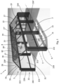
- reference number 1 indicates the greenhouse for cultivating plants, object of the present invention.
- the present greenhouse 1 is advantageously intended to be employed for housing at its interior one or more cultivations of plants, such as for example vegetables, fruit plants, flowers or ornamental plants.
- cultivations can be conducted directly on the ground, i.e. on the terrain on which the greenhouse is intended to be fixed, or in a vase.
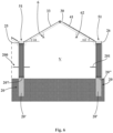
- the greenhouse 1 comprises a support framework 2, which is intended to be fixed to the ground, defines an internal volume V and comprises a first side 21 and a second side 22, extended substantially perpendicular to the ground and parallel to each other and to a main extension direction X.
- the support framework 2 comprises at least two first support uprights 210, each of which extended between a first lower end 211 thereof, intended to be fixed to the ground, and an opposite first upper end 212, and defining between them the aforesaid first side 21.
- the support framework 2 advantageously also comprises at least one first intermediate upright 210' placed between the first support uprights 210 and parallel thereto.
- the support framework 2 also comprises at least two second support uprights 220, each of which extended between a second lower end 221 thereof, intended to be fixed to the ground, and an opposite second upper end 222, and defining between them the second side 22.
- the support framework 2 advantageously also comprises at least one second intermediate upright 220' placed between the first support uprights 220 and parallel thereto.
- the support framework 2 comprises at least one first lateral crosspiece 25 and one second lateral crosspiece 26, placed parallel to each other and placed to respectively connect the first upper ends 212 of the first support uprights 210 and the second upper ends 222 of the second support uprights 220.
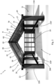
- the support framework 2 of the greenhouse 1 also comprises a first pitched roof 23, which is extended from the first side 21 and is tilted with a first tilt angle ⁇ 1, and a second pitched roof 24, which is extended from the second side 22 and is tilted with a second tilt angle ⁇ 2.
- first pitched roof 23 and the second pitched roof 24 are tilted towards each other and the first tilt angle ⁇ 1 is opposite the second tilt angle ⁇ 2.
- the first tilt angle ⁇ 1 is comprised between 20 and 40° and still more preferably is about 30°.
- the second tilt angle ⁇ 2 is comprised between 20 and 40° and still more preferably is about 30°.
- the tilt angles ⁇ 1, ⁇ 2 will suitably be intended as measured with respect to the horizon, i.e. the angles formed between the extensions of the planes of the roofs 23, 24 and the ground, as illustrated in figure 6 .
- the support framework 2 comprises at least two first tilted profiles 27, mechanically connected to the first lateral crosspiece 25 and defining the first pitched roof 23.
- the support framework 2 also comprises at least one first tilted intermediate profile 27' interposed between the first tilted profiles 27 and parallel thereto.
- the first tilted intermediate profile 27' is extended substantially starting from the corresponding first intermediate upright 210'.
- the support framework 2 also advantageously comprises at least two second tilted profiles 28, mechanically connected to the second lateral crosspiece 26 and defining the second pitched roof 24.
- the support framework 2 also comprises at least one second tilted intermediate profile 28' interposed between the second tilted profiles 28 and parallel thereto.
- the second tilted intermediate profile 28' is extended substantially starting from the corresponding second intermediate upright 220'.
- the presence of the intermediate uprights 210', 220' and of the tilted intermediate profiles 27', 28' advantageously allows rendering the support framework 2 more resistant, in particular if large size.
- the support framework 2 also advantageously comprises at least one top crosspiece 29, placed at the meeting of the first pitched roof 23 and the second pitched roof 24, parallel to the main extension direction X, and in particular supported by the first tilted profiles 27 and by the second tilted profiles 28.
- the various parts of the support framework 2 are fixed together by means of screws and/or brackets that are per se known in the field and therefore not described in detail hereinbelow.
- At least part of the support framework 2 (i.e. at least several between the uprights 210, 210', 220, 220', the crosspieces 25, 26, the tilted profiles 27, 27', 28, 28' and the top crosspiece 29) is attained by means of hollow profiles made of metal, preferably aluminum, in particular with square or rectangular section.
- the support framework 2 is completely attained with hollow aluminum profiles.
- the greenhouse 1 comprises a plurality of fixing elements 20, comprising an elongated body 20' intended to be planted in the ground, and an upper plate 20", to which it is fixed, e.g. by means of screws and bolts, the support framework 2, and in particular the lower end 211, 221 of a corresponding first support upright 210 thereof, first intermediate upright 210', second support upright 220 or second intermediate upright 220'.
- each aforesaid lower end 211, 221 comprises a respective lower plate in order to allow an easier fixing of the support framework 2.
- such fixing elements 20 are designed with a length depending on the type of ground on which said greenhouse 1 is intended to be mounted.
- the fixing elements 20 are made of metal, preferably of galvanized steel.
- the greenhouse 1 advantageously comprises a plurality of plates made of plastic material (not illustrated in the figures), each interposed between the corresponding upper plate 20" of the fixing element 20 and the support framework 2, in particular the lower end 211, 221 of its corresponding first support upright 210, first intermediate upright 210', second support upright 220 or second intermediate upright 220'.
- the greenhouse 1 comprises a plurality of transparent or translucent cover panels 3, fixed to the support framework 2 at least to cover the first pitched roof 23 and at least one between the first side 21 and the second side 22.
- cover panels 3 are fixed, for example by means of screws and/or brackets, at least to the first tilted profiles 27 and to the first support uprights 210 and/or second support uprights 220.
- cover panels 3 are preferably placed to completely cover the first tilted profiles 27 and the first support uprights 210 and/or second support uprights 220. In this manner, by completely covering the support framework 2, an optimal insulation of the internal volume V is obtained, allowing the elimination of possible heat bridges.
- the plurality of cover panels 3 comprises at least one first lateral panel 31 fixed to cover the first side 21 of the support framework 2, preferably fixed to the first support uprights 210.
- the plurality of cover panels 3 comprises at least one second lateral panel 32 fixed to cover the second side 22 of the support framework 2, preferably fixed to the second support uprights 220.
- the plurality of cover panels 3 comprises at least one upper panel 33 fixed to cover the first pitched roof 23 of the support framework 2, preferably fixed to the first tilted profiles 27.
- the plurality of cover panels 3 comprises at least one front panel 34 and a rear panel 35, which are placed to join together the first side 21 and the second side 22 of the support framework 2, on opposite sides of the support framework 2 itself.
- front and rear of the greenhouse 1 are interchangeable, rotating 180° around a vertical axis.
- the front panel 34 is constrained, preferably hinged, to one of the first support uprights 210 or of the second support uprights 220 placed frontal. In this manner, the front panel 34 can be opened and usable in order to access within the greenhouse 1.
- two front panels 34 are present, each hinged to a corresponding first support upright 210 and second support upright 220 placed frontal.
- the rear panel 35 is constrained, preferably hinged, to one of the first support uprights 210 or of the second support uprights 220 placed to the rear. In this manner, also the rear panel 35 is openable and usable for accessing within the greenhouse 1. In accordance with an embodiment variant, two rear panels 35 are present, each hinged to a corresponding first support upright 210 and second support upright 220 placed to the rear.
- the front panel 34 and the rear panel 35 can be made in any other way in order to allow the access to the greenhouse.
- the front 34 and rear 35 panel/panels can be foldable as bellows or slidably, or they can provide for through openings in which access doors are embedded.
- the cover panels 3 are made of plastic material or glass, still more preferably made of polycarbonate.
- the latter material is indeed resistant to hail, to UV rays and has a high durability.
- An important advantage of polycarbonate is that it retains heat very well, contributing to creating an ideal microclimate for the plants, and is therefore ideal for use in the greenhouse 1 according to the preferred embodiment of the invention. Its lightness also facilitates the attainment of the structure, as well as a possible substitution of the cover panels 3 in case of need.
- the use of polycarbonate is eco-sustainable, since it has a long duration and the cover panels 3 are completely recyclable.
- the greenhouse 1 also comprises at least one support panel 30, which is fixed to the support framework 2 to cover the second pitched roof 24. More in detail, the support panel 30 is fixed to the second tilted profiles 28. In addition, the support panel 30 is preferably placed to completely cover the second tilted profiles 28 in order to insulate them and prevent the formation of heat bridges.
- the support panel 30 is made of an insulating multilayer material, in particular opaque.
- the greenhouse 1 comprises only one support framework 2, i.e. only one pitched roof truss, and therefore such support framework 2 is entirely covered perimetrically, i.e. enclosed, by the cover panels 3.
- the greenhouse 1 comprises at least two support frameworks 2 facing each other with their main extension directions X parallel.
- the second side 22 of a first 2' of the two support frameworks 2 is in common with the first side 21 of an adjacent second 2" of the two support frameworks 2, and the plurality of cover panels 3 comprises at least one between a first lateral panel 31 fixed to cover the first side 21 of the first support framework 2' and a second lateral panel 32 fixed to cover the second side 22 of the adjacent second support framework 2".
- the cover panels might not cover each side 21, 22 of each support framework 2, but only the sides 21, 22 of the support frameworks 2 placed externally, so as to cover only the external perimeter of the greenhouse 1 and obtaining a single covered environment.
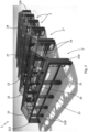
- the greenhouse 1 is substantially modular, being able to vary - depending on the structural needs - the length of the greenhouse 1 itself along the main extension direction X, for example by varying the distance between the support uprights 210, 220 of a same side and the quantity of intermediate uprights 210', 220' interposed therebetween.
- a single module M which can be spatially repeated is for example shown in figure 5 .
- cover panels 3 can also be placed on the sides 21, 22 between two support frameworks 2 in order to maintain multiple internal volumes V separated, for example if it is desired to recreate different environmental conditions.
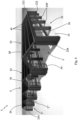
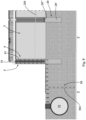
- the greenhouse also comprises energy supply means 4, comprising at least one photovoltaic module 41, which is mounted on the second pitched roof 24 in order to be exposed to sunrays and intended to convert the energy of the sunrays into electrical energy.
- energy supply means 4 comprising at least one photovoltaic module 41, which is mounted on the second pitched roof 24 in order to be exposed to sunrays and intended to convert the energy of the sunrays into electrical energy.
- the photovoltaic module 41 is about 615 Watt.
- the photovoltaic module 41 is mounted on the support panel 30, for example fixed to the latter by means of suitable brackets (not illustrated in the enclosed figures).
- the energy supply means 4 comprise a plurality of photovoltaic modules 41 in order to cover the entire second pitched roof 24, as is visible for example in figure 4 .
- the energy supply means 4 comprise at least one energy storage device, e.g. a battery, electrically connected to the photovoltaic module 41 in order to store the electrical energy generated by the photovoltaic module 41 itself.
- a battery electrically connected to the photovoltaic module 41 in order to store the electrical energy generated by the photovoltaic module 41 itself.
- the energy storage device is placed inside the internal volume V of the greenhouse 1.
- the energy supply means 4 are also connected to a power grid at least in order to introduce, in such power grid, the electrical energy generated in excess, not used and/or not stored in the energy storage device.
- the greenhouse also comprises water recovery means 5, arranged for recovering rainwater, and/or water extraction means 50, arranged for extracting water from an aquifer F.
- the greenhouse 1 comprises both such water recovery and extraction means 5, 50.
- the water recovery means 5 comprise one or more gutters 51, placed at the first and/or second lateral crosspiece 25, 26 and one or more uprights 210, 210', 220, 220', as illustrated for example in figures 6 and 8 .
- the gutters 51 are integrated in the support framework, i.e. they are integral with the first and/or second lateral crosspiece 25, 26 and with one or more uprights 210, 210', 220, 220'.
- the water recovery means 5 advantageously comprise at least one storage tank 52, preferably intended to be embedded, in fluid communication with the aforesaid gutters 51, in order to collect the water that flows from the latter.
- the water recovery means 5 are also arranged for recovering the condensation that forms, for example at night, outside of the cover panels 3 and that also in this case is intended to flow into the gutters 51.
- the water recovery means 5 comprise, in addition, a filtering device (not illustrated in the enclosed figures), arranged for filtering the collected water.
- the water extraction means 50 comprise one or more pipes 501, intended to be placed in hydraulic communication with an aquifer F deep underground, as illustrated for example in figures 7 and 8 .
- the water extraction means 50 comprise one or more extraction pumps (not illustrated in the enclosed figures) placed to intercept the pipes 501, in order to suction the water from the aquifer F.
- the extraction pump is electrically connected to the energy supply means 4 in order to be power supplied by the latter.
- the water extraction means 50 are also in fluid communication with the storage tank 52 for the water recovery means 5 so as to store, in the latter, also water suctioned from the aquifer F, as illustrated in figure 8 .
- the greenhouse 1 also comprises an irrigation plant 6, placed at least partially within the internal volume V of the greenhouse 1, hydraulically connected to the water recovery means 5 and/or to said water extraction means 50, preferably both, and arranged for irrigating the plants placed in the greenhouse 1.
- the irrigation plant 6 comprises, in a per se known manner, a plurality of channels 61, in fluid communication with water recovery means 5 and/or with said water extraction means 50 intercepted by a plurality of dispensing mouths 62.
- a "rain" irrigation plant is for example illustrated, fixed to the first pitched roof 23 and to the second pitched roof 24, in particular to the tilted profiles 27, 27', 28, 28'.
- the irrigation plant 6 can also be an irrigation plant on the ground or of any other type.
- the irrigation plant 6 comprises one or more irrigation pumps (not illustrated in the enclosed figures) in fluid communication with the channels 61 of the irrigation plant 6 and with the storage tank 52 for the water recovery means 5 and/or the pipe 501 of the water extraction means 50.
- the irrigation pump can coincide with the extraction pump.
- the irrigation pump is electrically connected to the energy supply means 4 in order to be power supplied by the latter.
- the greenhouse 1 also comprises a heating plant 7, electrically powered at least partially by the energy supply means 4 and arranged for heating the internal volume V of the greenhouse 1.
- the heating plant 7 comprises one or more heat pumps (not illustrated in the enclosed figures) power supplied by the energy supply means 4.
- the greenhouse 1 also comprises a ventilation plant 8, comprising at least one recirculation fan 81 for recirculating air within the internal volume V of the greenhouse 1, electrically power supplied at least partially by the energy supply means 4.
- the ventilation plant 8 also comprises at least one aeration grid 82, mounted at the first pitched roof 23 of the support framework 2 in order to selectively place in air communication the internal volume V with the greenhouse 1 exterior.
- the plurality of cover panels 3 comprises at least one upper panel 33, placed to cover said first pitched roof 23.
- at least one through opening is made on the upper panel 33.
- the aeration grid 82 is mounted on the upper panel 33, embedded in the through opening and is provided with a plurality of blades placed in series and rotatable between an open position, in which the internal volume V and the greenhouse 1 exterior are in air communication through the through opening, and a closed position, in which the blades are placed to close the through opening.
- At least one recirculation fan 81 is mounted at the first pitched roof 23, in particular at the through opening of the upper panel 33, so as to force the entrance of the air into the internal volume V of the greenhouse 1.
- the aeration grid 82 is superimposed on such recirculation fan 81, such to allow adjusting the entrance of air into the greenhouse 1 also with the opening and closing of the aeration grid 82.
- the ventilation plant 8 comprises a dehumidification device 83, which is placed within the internal volume V of the greenhouse 1 and is arranged for removing the humidity of the air.
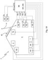
- the greenhouse 1 also comprises an environment control system 9 comprising at least one first temperature sensor 91 and at least one first humidity sensor 92, schematically illustrated in figure 10 .
- the first temperature sensor 91 is placed inside the internal volume V of the greenhouse 1 and is configured for determining an internal temperature data Ti and generating a corresponding internal temperature signal STi.
- the first humidity sensor 92 is placed inside the internal volume V of the greenhouse 1 and is configured for detecting internal environmental humidity data Ui and generating a corresponding internal humidity signal SUi.
- the greenhouse 1 also comprises a logic control unit 90, which is placed in data connection at least with the environment control system 9, the heating plant 7 and the ventilation plant 8 and is configured for receiving the internal temperature signal STi and the internal humidity signal SUi and, on the basis at least of the internal temperature data Ti and of the internal humidity data Ui, controlling the actuation of the heating plant 7 and/or of the ventilation plant 8.
- a logic control unit 90 which is placed in data connection at least with the environment control system 9, the heating plant 7 and the ventilation plant 8 and is configured for receiving the internal temperature signal STi and the internal humidity signal SUi and, on the basis at least of the internal temperature data Ti and of the internal humidity data Ui, controlling the actuation of the heating plant 7 and/or of the ventilation plant 8.
- the logic control unit 90 can actuate the heating plant 7 (by actuating the heat pump) and/or the ventilation plant 8 (by actuating the recirculation fan 81, the aeration grid 82 and/or the dehumidifier 83) when the internal temperature data Ti and/or the internal humidity data Ui exceed preset limit values on the basis of the cultivated plant, so as to bring such data back within a pre-established optimal interval.
- the greenhouse 1 according to the invention is arranged for being adapted to the needs of each cultivation type independent of the climate conditions outside of the greenhouse 1 itself, controlling internal temperature and humidity.
- the environment control system 9 also comprising a second temperature sensor 93 and a second humidity sensor 94, schematically illustrated in figure 10 .
- the second temperature sensor 93 is placed outside the internal volume V of the greenhouse 1 and is configured for determining an external temperature data Te and generating a corresponding external temperature signal STe.
- the second humidity sensor (94) is placed outside the internal volume V of the greenhouse 1 and is configured for detecting an external environmental humidity data Ue and generating a corresponding external humidity signal SUe.
- the logic control unit 90 is configured for also receiving the external temperature signal STe and the external humidity signal SUe and calculating a temperature difference DT, between the external temperature data Te and the internal temperature data Ti, and a humidity difference DU, between the external humidity data Ue and the internal humidity data Ui.
- the logic control unit 90 is advantageously configured for controlling, also on the basis at least of the temperature difference DT and of the humidity difference DU, the actuation of the heating plant 7 and/or of the ventilation plant 8.
- the logic control unit 90 can establish if it is more convenient to actuate the heating plant 7 or the ventilation plant 8 based on the comparison of the temperature and humidity data.
- the environment control system 9 also comprises at least one third humidity sensor 95, schematically illustrated in figure 10 , which is intended to be placed within the ground in which the plants are planted and is configured for determining a ground humidity data Ut and generating a corresponding ground humidity signal SUt.
- the logic control unit 90 is placed in data connection also with said irrigation plant 6 and is configured for receiving the ground humidity signal SUt and, on the basis at least of the ground humidity data Ut, controlling the actuation of the irrigation plant 6.
- the logic control unit 90 can actuate the irrigation plant 6.
- the logic control unit 90 can actuate the heating plant 7 or the ventilation plant 8 in order to remove the humidity from the ground.
- the greenhouse 1 also comprises illumination means 70 placed within the internal volume V of the greenhouse 1 and electrically power supplied at least partially by the energy supply means 4.
- the illumination means 70 comprise LED lamps, preferably infrared, still more preferably of the type known as "grow light", capable of balancing hot and cold light of the LEDs in order to accurately reproduce the natural light.
- the illumination means 70 are advantageously placed below the second pitched roof 24 and preferably also the first pitched roof 23, and advantageously fixed to the relative tilted profiles 27, 27', 28, 28'.
- the environment control system 9 also comprises at least one brightness sensor 96, for example a twilight sensor, illustrated schematically in figure 10 , which is intended to be placed within the internal volume V of the greenhouse 1 and is configured for determining internal brightness data Li and generating a corresponding internal brightness signal SLi.
- at least one brightness sensor 96 for example a twilight sensor, illustrated schematically in figure 10 , which is intended to be placed within the internal volume V of the greenhouse 1 and is configured for determining internal brightness data Li and generating a corresponding internal brightness signal SLi.
- the logic control unit 90 is advantageously placed in data connection also with the illumination means 70 and is configured for receiving the internal brightness signal SLi and, on the basis at least of the internal brightness data Li, controlling the actuation of the illumination means 70.
- the logic control unit 90 can be completely managed remotely.
- the logic control unit 90 is advantageously connected to an Internet network, to which also one or more of the utilities (such as for example the water recovery means 5, the water extraction means 50, the irrigation plant 6, the heating plant 7, the ventilation plant 8, the environment control system 9 and the illumination means 70) can be connected in a manner such that also the latter can be controlled by the logic control unit 90 or directly by a user without requiring a connection via cable.
- the utilities such as for example the water recovery means 5, the water extraction means 50, the irrigation plant 6, the heating plant 7, the ventilation plant 8, the environment control system 9 and the illumination means 70
- the greenhouse 1 also comprises movement means 200, which are placed at least partially within the internal volume V of said greenhouse 1, preferably completely within such internal volume V, and comprise at least one conveyor belt 201, extended along a transport direction T, preferably parallel to the main extension direction X.
- the conveyor belt 201 is extended at the first and/or the second side 21, 22 of the greenhouse 1.
- the conveyor belt 201 allows moving farming products inside or towards the outside of the greenhouse 1 with greater ease, speed and lower work force.
- the invention thus conceived, in accordance with the preferred embodiment, is capable of ensuring the recreation of an ideal controlled microclimate within the greenhouse 1, allowing the cultivation year-round.
- the environment control system 9 advantageously allows the microclimate management of the internal volume V and always ensures ideal temperatures and humidity, even with adverse external conditions.
- This microclimate is also adjustable based on the type of culture selected by means of a remote plant adjustment system, which interacts with the logic control unit 90.
- such greenhouse 1 is preferably only power supplied with electric current produced by the photovoltaic modules 41 installed on the second pitched roof 24, thus lowering the external electrical supply required, in particular from non-renewable sources, hence reducing the environmental impact.
- such greenhouse 1 is preferably hydraulically supplied only by the water recovery means 5 and/or by the water extraction means 50.
- the greenhouse 1 is advantageously intended to be self-sufficient at least in terms of energy and water supply.
- the entire structure of the greenhouse 1, i.e. in particular the support framework 2 and the cover panels 3, has a sustainable life-cycle due to the use of selected materials (in particular preferably aluminum and polycarbonate) which at the end of an average lifetime of the greenhouse 1 of about 30 years can be easily recycled or reused.
- selected materials in particular preferably aluminum and polycarbonate
- the support framework 2 and the cover panels 3 in accordance with the preferred embodiment ensure the protection from hail and an optimal natural irradiation for the cultivations.
- the greenhouse 1 is advantageously structurally modular, in accordance with the described embodiment variants, allowing being adapted to the needs of the farmer and of the terrain due to the completeness of each single module.
- Also forming the object of the present invention is a process for installing a greenhouse 1 for cultivating plants of the above-described type, regarding which the same reference numbers will be maintained for the sake of descriptive clarity.
- the process, object of the invention comprises a first fixing step, in which the support framework 2 is fixed to the ground, with the first pitched roof 23 directed in north direction and the second pitched roof 24 directed in south direction.
- the fixing elements 20 are initially fixed in the ground, and fixed thereto are the corresponding uprights 210, 210', 220, 220', with the panels made of plastic material advantageously interposed.
- Advantageously fixed on the uprights 210, 210', 220, 220' are the first and the second lateral crosspieces 25, 26, the tilted profiles 27, 27', 28, 28', and the top crosspiece 29.
- the process according to the invention also comprises a second fixing step, in which the plurality of cover panels 3 is fixed to the support framework 2 to cover at least the first pitched roof 23 and with at least one between the first side 21 and the second side 22.
- the support panel 30 also fixed to the second pitched roof 24 is the support panel 30.
- the process also comprises a mounting step, in which the at least one photovoltaic module 41 of the energy supply means 4 is mounted on the second pitched roof 24 directed substantially southward.
- the photovoltaic module 41 is fixed to the support panel 30, for example by means of brackets of known type.
- the photovoltaic module 41 has the best exposure for being irradiated by the sunrays.
- Such condition is further improved by the improved tilt of the second pitched roof 24, which as stated above is preferably comprised between 20 and 40°, and still more preferably is about 30°.
- the energy storage device advantageously installed and connected electrically to the photovoltaic module 41.
- the process according to the invention also comprises a water installation step, in which the water recovery means 5 and/or the water extraction means 50 are installed, together with the irrigation plant 6.
- the irrigation plant 6 is hydraulically connected to the water recovery means 5 and/or to the water extraction means 50, preferably to both.
- the process also comprises a utility installation step, in which the heating plant 7 and the ventilation plant 8 are installed.
- the heating plant 7 and the recirculation fan 81 of the ventilation plant 8 are electrically connected to the energy supply means 4.
- the aeration grid 82 of the aeration plant 8 is also installed.
- the dehumidification device 83 of the aeration plant 8 is also installed.
- the illumination means 70 are installed.
- the process according to the invention also comprises a sensor installation step, in which the environment control system 9 is installed and connected to the logic control unit 90.
- the water recovery means 5 the water extraction means 50, the irrigation plant 6, the heating plant 7, the ventilation plant 8, the environment control system 9 and the illumination means 70.
- the invention thus conceived therefore attains the pre-established objects.
Landscapes
- Life Sciences & Earth Sciences (AREA)
- Environmental Sciences (AREA)
- Engineering & Computer Science (AREA)
- Sustainable Development (AREA)
- Sustainable Energy (AREA)
- Greenhouses (AREA)
Applications Claiming Priority (1)
| Application Number | Priority Date | Filing Date | Title |
|---|---|---|---|
| IT202300017262 | 2023-08-11 |
Publications (1)
| Publication Number | Publication Date |
|---|---|
| EP4505865A1 true EP4505865A1 (fr) | 2025-02-12 |
Family
ID=88689631
Family Applications (1)
| Application Number | Title | Priority Date | Filing Date |
|---|---|---|---|
| EP24193694.7A Pending EP4505865A1 (fr) | 2023-08-11 | 2024-08-08 | Serre pour la culture de plantes et procédé d'installation de ladite serre |
Country Status (1)
| Country | Link |
|---|---|
| EP (1) | EP4505865A1 (fr) |
Citations (5)
| Publication number | Priority date | Publication date | Assignee | Title |
|---|---|---|---|---|
| CN107873477A (zh) * | 2017-11-14 | 2018-04-06 | 许小球 | 一种具有降温功能的光伏与绿化复合系统及其控制方法 |
| CN207410956U (zh) * | 2017-10-25 | 2018-05-29 | 成都常明信息技术有限公司 | 一种节能温室大棚 |
| WO2019049094A1 (fr) * | 2017-09-11 | 2019-03-14 | Rem Tec S.R.L. | Centrale de production d'énergie solaire pouvant être installée sur des installations agricoles |
| CN107810751B (zh) * | 2017-10-31 | 2021-01-01 | 台州中知英健机械自动化有限公司 | 一种可集雨灌溉的智能农业大棚 |
| GB2613903A (en) * | 2021-01-04 | 2023-06-21 | TEP RENEWABLES Ltd | Agricultural photovoltaic structure with controlled cooling |
-
2024
- 2024-08-08 EP EP24193694.7A patent/EP4505865A1/fr active Pending
Patent Citations (5)
| Publication number | Priority date | Publication date | Assignee | Title |
|---|---|---|---|---|
| WO2019049094A1 (fr) * | 2017-09-11 | 2019-03-14 | Rem Tec S.R.L. | Centrale de production d'énergie solaire pouvant être installée sur des installations agricoles |
| CN207410956U (zh) * | 2017-10-25 | 2018-05-29 | 成都常明信息技术有限公司 | 一种节能温室大棚 |
| CN107810751B (zh) * | 2017-10-31 | 2021-01-01 | 台州中知英健机械自动化有限公司 | 一种可集雨灌溉的智能农业大棚 |
| CN107873477A (zh) * | 2017-11-14 | 2018-04-06 | 许小球 | 一种具有降温功能的光伏与绿化复合系统及其控制方法 |
| GB2613903A (en) * | 2021-01-04 | 2023-06-21 | TEP RENEWABLES Ltd | Agricultural photovoltaic structure with controlled cooling |
Similar Documents
| Publication | Publication Date | Title |
|---|---|---|
| JP3177129U (ja) | モジュール化可能なソーラエネルギ施設の温室棚 | |
| US9468157B2 (en) | Three-dimensional planting construction | |
| CN102400568B (zh) | 生态环保能源综合建筑大楼 | |
| KR910002378B1 (ko) | 재배용온실 | |
| CN206791172U (zh) | 一种可分区调整遮光的太阳能大棚 | |
| CN111937647A (zh) | 一种绿色节能建筑 | |
| KR100951597B1 (ko) | 루프 어셈블리를 구비한 화분 | |
| CA3186647A1 (fr) | Installation de production d'energie electrique pouvant etre installee sur des structures et/ou des sols agricoles | |
| WO2024134637A2 (fr) | Installation solaire avec système d'espace fermé | |
| CN1167321C (zh) | 一种日光温室 | |
| KR101547864B1 (ko) | 태양에너지 수집유닛을 구비한 버섯 재배시설 | |
| CN207151344U (zh) | 一种半地下式阴阳温室大棚 | |
| CN116113316A (zh) | 农业光伏模块 | |
| CN104737853A (zh) | 一种果树专用不对称拱轨日光温室系统及其建造方法 | |
| CN103960077A (zh) | 立体生态种植屋 | |
| EP4505865A1 (fr) | Serre pour la culture de plantes et procédé d'installation de ladite serre | |
| WO2020171781A1 (fr) | Système d'auto-approvisionnement de bâtiments et de résidents | |
| JP4137833B2 (ja) | 屋根構造 | |
| KR20210072688A (ko) | 영농지에 구축된 태양광, 강풍유도용 태양광발전판 | |
| CN106258677A (zh) | 一种市政智能型园林用幼苗安全保护装置 | |
| KR102114528B1 (ko) | 조림수에서 공기정화용 에너지 포집장치 | |
| CN209788007U (zh) | 一种玻璃连栋温室大棚 | |
| CN109548526A (zh) | 温控智能光电大棚及应用方法 | |
| US20260071608A1 (en) | Solar Vortex Clamshell Greenhouse | |
| CN219421712U (zh) | 一种结合光伏板的农用大棚 |
Legal Events
| Date | Code | Title | Description |
|---|---|---|---|
| PUAI | Public reference made under article 153(3) epc to a published international application that has entered the european phase |
Free format text: ORIGINAL CODE: 0009012 |
|
| STAA | Information on the status of an ep patent application or granted ep patent |
Free format text: STATUS: THE APPLICATION HAS BEEN PUBLISHED |
|
| AK | Designated contracting states |
Kind code of ref document: A1 Designated state(s): AL AT BE BG CH CY CZ DE DK EE ES FI FR GB GR HR HU IE IS IT LI LT LU LV MC ME MK MT NL NO PL PT RO RS SE SI SK SM TR |
|
| P01 | Opt-out of the competence of the unified patent court (upc) registered |
Free format text: CASE NUMBER: APP_13681/2025 Effective date: 20250319 |
|
| STAA | Information on the status of an ep patent application or granted ep patent |
Free format text: STATUS: REQUEST FOR EXAMINATION WAS MADE |
|
| 17P | Request for examination filed |
Effective date: 20250812 |