EP4505903A1 - Système de cadre à monter dans un meuble de travail et meuble de travail - Google Patents
Système de cadre à monter dans un meuble de travail et meuble de travail Download PDFInfo
- Publication number
- EP4505903A1 EP4505903A1 EP24191433.2A EP24191433A EP4505903A1 EP 4505903 A1 EP4505903 A1 EP 4505903A1 EP 24191433 A EP24191433 A EP 24191433A EP 4505903 A1 EP4505903 A1 EP 4505903A1
- Authority
- EP
- European Patent Office
- Prior art keywords
- frame
- module
- modules
- frame module
- base
- Prior art date
- Legal status (The legal status is an assumption and is not a legal conclusion. Google has not performed a legal analysis and makes no representation as to the accuracy of the status listed.)
- Pending
Links
Images


Classifications
-
- A—HUMAN NECESSITIES
- A47—FURNITURE; DOMESTIC ARTICLES OR APPLIANCES; COFFEE MILLS; SPICE MILLS; SUCTION CLEANERS IN GENERAL
- A47B—TABLES; DESKS; OFFICE FURNITURE; CABINETS; DRAWERS; GENERAL DETAILS OF FURNITURE
- A47B77/00—Kitchen cabinets
- A47B77/04—Provision for particular uses of compartments or other parts ; Compartments moving up and down, revolving parts
- A47B77/06—Provision for particular uses of compartments or other parts ; Compartments moving up and down, revolving parts for incorporating sinks, with or without draining boards, splash-backs, or the like
-
- A—HUMAN NECESSITIES
- A47—FURNITURE; DOMESTIC ARTICLES OR APPLIANCES; COFFEE MILLS; SPICE MILLS; SUCTION CLEANERS IN GENERAL
- A47B—TABLES; DESKS; OFFICE FURNITURE; CABINETS; DRAWERS; GENERAL DETAILS OF FURNITURE
- A47B96/00—Details of cabinets, racks or shelf units not covered by a single one of groups A47B43/00 - A47B95/00; General details of furniture
-
- A—HUMAN NECESSITIES
- A47—FURNITURE; DOMESTIC ARTICLES OR APPLIANCES; COFFEE MILLS; SPICE MILLS; SUCTION CLEANERS IN GENERAL
- A47B—TABLES; DESKS; OFFICE FURNITURE; CABINETS; DRAWERS; GENERAL DETAILS OF FURNITURE
- A47B13/00—Details of tables or desks
- A47B13/02—Underframes
-
- A—HUMAN NECESSITIES
- A47—FURNITURE; DOMESTIC ARTICLES OR APPLIANCES; COFFEE MILLS; SPICE MILLS; SUCTION CLEANERS IN GENERAL
- A47B—TABLES; DESKS; OFFICE FURNITURE; CABINETS; DRAWERS; GENERAL DETAILS OF FURNITURE
- A47B77/00—Kitchen cabinets
-
- A—HUMAN NECESSITIES
- A47—FURNITURE; DOMESTIC ARTICLES OR APPLIANCES; COFFEE MILLS; SPICE MILLS; SUCTION CLEANERS IN GENERAL
- A47B—TABLES; DESKS; OFFICE FURNITURE; CABINETS; DRAWERS; GENERAL DETAILS OF FURNITURE
- A47B9/00—Tables with tops of variable height
-
- A—HUMAN NECESSITIES
- A47—FURNITURE; DOMESTIC ARTICLES OR APPLIANCES; COFFEE MILLS; SPICE MILLS; SUCTION CLEANERS IN GENERAL
- A47B—TABLES; DESKS; OFFICE FURNITURE; CABINETS; DRAWERS; GENERAL DETAILS OF FURNITURE
- A47B95/00—Fittings for furniture
- A47B95/04—Keyplates; Ornaments or the like
-
- A—HUMAN NECESSITIES
- A47—FURNITURE; DOMESTIC ARTICLES OR APPLIANCES; COFFEE MILLS; SPICE MILLS; SUCTION CLEANERS IN GENERAL
- A47B—TABLES; DESKS; OFFICE FURNITURE; CABINETS; DRAWERS; GENERAL DETAILS OF FURNITURE
- A47B96/00—Details of cabinets, racks or shelf units not covered by a single one of groups A47B43/00 - A47B95/00; General details of furniture
- A47B96/04—Partition walls
-
- A—HUMAN NECESSITIES
- A47—FURNITURE; DOMESTIC ARTICLES OR APPLIANCES; COFFEE MILLS; SPICE MILLS; SUCTION CLEANERS IN GENERAL
- A47B—TABLES; DESKS; OFFICE FURNITURE; CABINETS; DRAWERS; GENERAL DETAILS OF FURNITURE
- A47B2230/00—Furniture jointing; Furniture with such jointing
- A47B2230/0074—Mortise and tenon joints or the like including some general male and female connections
- A47B2230/0081—Mortise and tenon type joints with some general male and female joints
-
- A—HUMAN NECESSITIES
- A47—FURNITURE; DOMESTIC ARTICLES OR APPLIANCES; COFFEE MILLS; SPICE MILLS; SUCTION CLEANERS IN GENERAL
- A47B—TABLES; DESKS; OFFICE FURNITURE; CABINETS; DRAWERS; GENERAL DETAILS OF FURNITURE
- A47B47/00—Cabinets, racks or shelf units, characterised by features related to dismountability or building-up from elements
- A47B47/0091—Modular arrangements of similar assemblies of elements
-
- A—HUMAN NECESSITIES
- A47—FURNITURE; DOMESTIC ARTICLES OR APPLIANCES; COFFEE MILLS; SPICE MILLS; SUCTION CLEANERS IN GENERAL
- A47B—TABLES; DESKS; OFFICE FURNITURE; CABINETS; DRAWERS; GENERAL DETAILS OF FURNITURE
- A47B77/00—Kitchen cabinets
- A47B77/04—Provision for particular uses of compartments or other parts ; Compartments moving up and down, revolving parts
- A47B77/18—Provision for particular uses of compartments or other parts ; Compartments moving up and down, revolving parts by special arrangements for accommodating removable containers
-
- F—MECHANICAL ENGINEERING; LIGHTING; HEATING; WEAPONS; BLASTING
- F16—ENGINEERING ELEMENTS AND UNITS; GENERAL MEASURES FOR PRODUCING AND MAINTAINING EFFECTIVE FUNCTIONING OF MACHINES OR INSTALLATIONS; THERMAL INSULATION IN GENERAL
- F16B—DEVICES FOR FASTENING OR SECURING CONSTRUCTIONAL ELEMENTS OR MACHINE PARTS TOGETHER, e.g. NAILS, BOLTS, CIRCLIPS, CLAMPS, CLIPS OR WEDGES; JOINTS OR JOINTING
- F16B12/00—Jointing of furniture or the like, e.g. hidden from exterior
- F16B12/10—Jointing of furniture or the like, e.g. hidden from exterior using pegs, bolts, tenons, clamps, clips, or the like
- F16B12/28—Jointing of furniture or the like, e.g. hidden from exterior using pegs, bolts, tenons, clamps, clips, or the like for metal furniture parts
- F16B12/32—Jointing of furniture or the like, e.g. hidden from exterior using pegs, bolts, tenons, clamps, clips, or the like for metal furniture parts using clamps, clips, wedges, sliding bolts, or the like
Definitions
- the invention relates to a frame system for installation in a work furniture.
- the invention further relates to a work furniture with a frame system.
- Kitchen base cabinets are usually used to accommodate different devices, such as a waste separation system for a sink user and possibly a water treatment system or the like. Since individual constraints such as the width, depth and height of the kitchen base cabinet, which can also be changed by a user at short notice, often have to be taken into account, it has become common practice to attach the individual devices directly to the base cabinet or its movable front, for example to a door. The individual devices have a wide variety of dimensions and are attached on site by a fitter in a position in the base cabinet that suits him, which requires an extremely high level of assembly work in terms of time and complexity.
- a rectangular installation frame in the base cabinet which is fixed in the base cabinet, comprising interconnected frame struts forming a substantially rectangular frame, auxiliary struts attached to the frame and lying in the frame plane, angle valves attached to an auxiliary strut with pressure-resistant connecting hoses for an over-sink outlet fitting and for connection to water inlet pipes on the wall, wherein the complete auxiliary installation frame can be used in the chamber of the base cabinet which is substantially open to the wall behind it and can be attached to the floor and/or the side walls of the base cabinet, as well as a cover which covers the installation frame at the front and is detachably attached to the installation frame.
- the DE 10 2021 203 803 A1 A two-part frame module has become known, which can be divided into functional components by means of separating elements within the frame module.
- the disadvantage is that although it is possible to pre-assemble the frame module with functional components such as drawers, a water treatment unit or the like, it is considerably more difficult for a fitter to transport the frame module with the pre-installed functional components on site at the customer's premises due to the associated high weight.
- Another disadvantage is that a different arrangement of the functional components, for example the drawer on the left and the water treatment unit on the right depending on the customer's wishes, is not possible without complex dismantling and reassembly.
- the width of the frame module cannot be changed either, which makes it impossible to adapt it to a base cabinet with different dimensions.
- An object of the present invention is therefore to provide a frame system and a work furniture with a frame system, which can be adapted more flexibly to different dimensions of base cabinets and at the same time enable improved handling on site at the customer.
- a further object of the present invention is to provide an alternative frame system and an alternative work furniture with a frame system.
- the present invention solves the above-mentioned problems with a frame system for installation in a work piece of furniture, in particular a sanitary work piece of furniture, comprising a first frame module and a second frame module, wherein the first and the second frame module each have at least one insertion opening for the insertion of at least one pre-installed functional component for a user, wherein the respective insertion opening has a square cross-section, and wherein the first and second frame modules can be fixed to one another by means of a tool-free connection.
- the present invention solves the above-mentioned problems with a work furniture with a frame system according to one of claims 1-14.
- sanitary is to be understood in the broadest sense and refers, in particular in the description, preferably in the claims, among other things, to any objects, arrangements, devices, equipment and the like in connection with bathrooms, kitchens, heating systems and the like.
- installation in a work piece of furniture is to be understood in the broadest sense and refers, in particular in the claims, preferably in the description, to any arrangement in, on, between or under one or more work pieces of furniture.
- the wording refers not only to installation of the frame system in a work piece of furniture, but also to the arrangement on a floor under a worktop and between two separate work pieces of furniture.
- tool-free connection is to be understood in the broadest sense and refers, in particular in the claims, preferably in the description, to any form-fitting, material-fitting and/or force-fitting connection that can be made manually and/or using objects not defined as a tool and can also be released again if necessary.
- a tool-free connection can be, for example, a snap-in connection in which a tab engages in a corresponding opening when the corresponding component with the tab is manually inserted into a component with the opening.
- the snap-in connection can then be released again either manually or using an object, for example a pencil, by pressing in or lifting the tab.
- the pencil does not represent a tool in the sense of the present invention.
- the frame modules can also be adapted more flexibly to different dimensions of base cabinets.
- one of the frame modules can always have the same dimensions and the other of the two frame modules can have different dimensions in order to be able to take different dimensions of base cabinets into account when arranging the two frame modules. Since the first frame module always has the same dimensions, it can be manufactured cost-effectively, which reduces the cost of the frame system as a whole.
- a third frame module can be fixed to one side of the first and second frame modules, with the sides of the first and second frame modules forming a common plane.
- the third frame module can be fixed to the first and/or second frame module, in particular to both frame modules, without tools.
- the advantage of this is that the third frame module can be fixed quickly and easily.
- the first frame module and the second frame module have a different cross-section with respect to the respective insertion opening.
- the advantage of this is greater flexibility with regard to the arrangement of, in particular, pre-installed functional components.
- the first and second frame modules are designed in such a way that they can be arranged next to one another in any arrangement along a predeterminable direction. This also increases flexibility and at the same time reduces costs. For example, it is possible for the first frame module to be arranged on the left and right sides of the front view. as well as on the right side of the second frame module.
- the first and/or second frame module can be designed in such a way that they can be arranged symmetrically, for example when rotated by 180 degrees around a vertical axis, on the other side of the respective other module.
- a fourth frame module is arranged as a base module, wherein the base module can be fixed to one side of the first and second frame module, wherein the sides of the first and second frame module form a common plane, in particular wherein the base module can be arranged on the opposite side of the third frame module on the first and second frame module.
- the base module has a height adjustment device for height and/or level regulation and/or a distance adjustment device for setting a distance to a surrounding element, in particular a wall.
- the tool-free connection is provided in the form of a plug connection and/or in the form of a particularly detachable clip and/or latching connection.
- At least one cover strip can be arranged on at least one of the frame modules.
- the at least one cover strip can be connected to the at least one frame module in a detachable or non-detachable manner, in particular by means of an adhesive connection.
- a detachable connection is that the frame system can be dismantled if necessary in the event of maintenance.
- the advantage of a non-detachable connection is that a particularly simple and cost-effective connection is provided.
- one or more fixing elements are arranged for securing the frame modules to one another and/or for securing at least one cover strip to at least one of the frame modules.
- the third frame module has a U-shaped cross-section, comprising a base and two lateral legs, wherein the third frame module can be fixed with its base to the first and second frame module.
- the third frame module has a particularly rectangular recess on the two side legs.
- At least one drawer element and/or a waste separation element and/or a water treatment unit can be arranged in one or more of the frame modules.
- the base module is connected by means of a detachable connection, in particular a screw and/or snap-in connection, and/or a permanent connection, in particular an adhesive connection, with the first and second frame module.
- a detachable connection in particular a screw and/or snap-in connection
- a permanent connection in particular an adhesive connection
- the third frame module has an edge, in particular an upstand, which is oriented perpendicular to the common plane, in particular wherein this is arranged opposite to a fold of the first and/or second frame module in the area where the third frame module rests on the first and second frame modules.
- the plug connection can be provided in the form of a U-shaped fold on one of the two frame modules, the first and second frame module, which can be pushed over an edge of the other of the two frame modules.
- the third frame module has a U-shaped fold that can be pushed over an edge of the first and/or second frame module.
- a compensation module and/or a storage module can be attached to the work furniture and/or the frame system.
- the advantage of this is that the flexibility of adaptability to different dimensions of work furniture or functional components is increased.
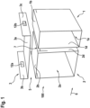
- Figure 1 shows a frame system according to an embodiment of the present invention.
- a frame system 100 which comprises two frame modules 1, 2 with a rectangular cross-section.
- the frame modules 1, 2 each have a Insertion opening 1a, 2a.
- the two frame modules 1, 2 can be secured to one another by means of a tool-free connection, here a plug connection 7.
- the first frame module 1 can be secured with its left side surface 1d to the right side surface 2d of the second frame module 2.
- a third frame module 3 is arranged, which has a U-shape in cross section with a base 3a that rests on the top sides 1b, 2b of the frame modules 1, 2 and is detachably connected to the frame modules 1, 2 and with two legs 3b, 3c that protrude vertically upwards from the plane 5.
- the legs 3b, 3c each have a lateral recess 12a, 12b, which is rectangular.
- the third frame module 3 is designed such that it extends along the direction 6 over the entire width of the two frame modules 1, 2.
- the depth of the third frame module 3 is less than the depth of the two frame modules 1, 2.
- Figure 2 shows a work furniture according to an embodiment of the present invention.
- a work furniture 200 which is essentially box-shaped.
- a first frame module 1 is arranged on the right-hand side and a second frame module 2 is arranged to the left of it.
- Both frame modules 1, 2 are arranged on a base of the work furniture 200 and, if necessary, secured to it.
- the two frame modules 1, 2 are also secured to one another without tools.
- a water treatment unit 15 is arranged in the first frame module 1, in the second frame module 2 in the lower area there is a pull-out waste bin 14 and above it a drawer element 13a.
- a panel 21 is arranged on the work furniture 200.
- an organizational shelf 20 is arranged directly on the work furniture 200, which is located below a crossbar 22 of the work furniture 200. In this way, gaps between the modules can be covered or concealed, so that a high-quality overall visual impression is maintained.
- Figure 3 shows a frame system according to an embodiment of the present invention.
- FIG 3 is essentially a frame system 100 according to Figure 1
- a fourth frame module 4 is shown in the form of a base module.
- the two frame modules 1, 2 are connected with their respective undersides 1c, 2c, which form a common plane 5a, to the top of the base module 4, in particular detachably by means of screws 11c, 11d, 11e.
- the two frame modules 1, 2 are detachably secured to one another by means of additional fixing elements, here in the form of screws 11a, 11b.
- L-shaped cover strips 10a, 10b are arranged by means of an adhesive connection on the right side surface 2d and on the left side surface 1d of the first and second frame modules 1, 2 as well as on the outer surfaces of the third frame module 3 corresponding to the side surfaces 1d, 2d. These serve to compensate or cover gaps between the frame module 1, 2 and a work furniture 200.
- the base module 4 also has height-adjustable feet 8 and depth-adjustable spacers 9 in the rear area.
- the modular structure of the frame system 100 shown in the figures comprises an embodiment with a frame system with base module 4, a first and second frame module 1, 2 as a common base module, a panel module 21, a drawer module 3 as a third frame module and an organization module 20.
- the modules 4, 1, 2, 3, 21, 20 are placed on top of one another and connected in a vertical direction.
- the base module 4 is not required for assembly, for example in a kitchen base cabinet.
- the panel module 21 and the drawer module 3 are designed in such a way that they can be arranged accordingly depending on the planning requirements or that the drawer module 3 is at least partially installed under the panel module 21.
- the organization module 20 forms the end upwards.
- the height of the panel module 21 and the drawer module 3 can be designed in such a way that the combination of the two modules 3, 21 or the omission of one of the modules 3, 21, in combination with the displacement path of the organization module 20 in the vertical direction, can provide the greatest possible accuracy of fit in relation to the variance of the body heights of base cabinets of work furniture 200.
- the modular arrangement shown here in the horizontal direction is designed for the 60 cm wide kitchen base cabinet and can be adapted in the sense of the present invention for both narrower and wider kitchen base cabinets in the horizontal extension.
- the base module is divided into at least two sub-modules - first and second frame module 1, 2.
- the division can be made at least vertically.
- the base module 1, 2 or the modules 3, 20, 21 above it can be designed symmetrically or asymmetrically in the horizontal direction.
- the frame modules 1, 2 are designed in such a way that they can each represent the right and left variant of the frame module 1, 2. For this, the respective module 1, 2 is rotated 180 degrees around a vertical axis and then connected to one another.
- the connection of the modules 1, 2, which can be detachable or non-detachable can be made during production or by means of special sheet metal connections during assembly at the customer's site. Screw connections, press-in elements, etc. can be used as connecting elements for the modules.
- One of the two frame modules 1, 2 can, for example, comprise a water treatment unit 15.
- the water treatment unit 15 can be installed directly in the respective frame module 1, 2 and not just pushed into the frame module 1, 2.
- the outer shell of the respective frame module 1, 2 thus also represents the outer shell of the water treatment unit 15.
- the water treatment unit 15 can be mounted on a carrier unit (not shown) and then inserted into the respective frame module 1, 2 during assembly. Cables and connecting lines are routed through a rear and/or front panel of the water treatment module 15 or connected to them.
- the modules placed on the two frame modules 1, 2 can have a smaller depth in order to avoid collisions with a sink or a drain pipe.
- the panel module 21 is designed such that its geometry and/or cross-section contributes to stiffening the entire frame system 100 with regard to deflection and/or torsion.
- the panel module 21 can extend over the entire width, defined by the plane 5 of the insertion openings 1a, 2a, of the frame system 100.
- it can be designed such that it has a rectangular frame with an inserted panel in the front view. This can have the advantage that access to the panel module 21 is possible.
- This opening option in turn makes it possible to arrange technical devices or functional elements in the panel module 21. These can include, for example, hose guides/hose winders for fittings with pull-out showers or water distribution modules.
- the base module 4 can be supplied as a separate component with the frame system 100.
- the assembly sequence changes in that the base module 4 is first arranged between existing kitchen base cabinets and is aligned using leveling screws 11c, 11d, 11e.
- the spacing from the wall or the adjacent cabinets can be achieved using screw-like elements 9.
- the spacing can also be achieved using sheet metal elements molded onto the base module.
- cover strips 10a, 10b can be arranged on the sides of the frame system 100, which comprises at least the frame modules 1, 2 and at least the third frame element 3 and which is delivered fully assembled.
- These cover strips 10a, 10b can be made from the same material as the neighboring carcasses and can, for example, be cut to size directly on site from prefabricated fitting strips.
- two double-sided adhesive tapes can be provided on each side to facilitate positioning of the fitting strips.
- the side panels 10a, 10b are fixed by means of a screw connection through holes provided in the frame system 100.
- the side fitting strips can be attached by means of clip, plug and/or snap connections.
- the front panels mentioned can be arranged laterally on the frame system 100 by means of angle pieces. This can have the advantage that the functional components of the frame element 100 are not covered by the front panels.
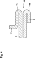
- FIGS. 4 and 5 each show a cross-section in the region of the attachment of a third frame module to a first frame module of a frame system according to an embodiment of the present invention.
- FIG 4 a cross section parallel to a side wall of a frame module 1, 2 is shown, more precisely the contact area 18, where the third frame module 3 rests against the first and second frame modules 1, 2.
- the frame module is designated with the reference number 1, but this can alternatively or additionally also apply to the second frame module 2.
- the first frame module 1 has a fold bent inwards, i.e. in the direction of insertion into the insertion opening 1a of the frame module 1.
- the third frame module 3 has a fold 16a which runs mirror-symmetrically to the top side 1b of the first frame element 1 and which has a vertical upstand 17 in the area facing away from the insertion opening 1a.
- the first frame module 1 no longer has a fold.
- the third frame module 3 has a fold 16c bent downwards in the direction of the insertion opening 1a, which is designed in such a way that it partially encompasses or surrounds a straight edge 19 of the first frame module 1.
- the third frame module 3 can be attached to the first frame module 1 by means of a plug connection
- the same can also be provided for a connection between the first and second frame module 1, 2.
Landscapes
- Assembled Shelves (AREA)
Applications Claiming Priority (1)
| Application Number | Priority Date | Filing Date | Title |
|---|---|---|---|
| DE102023207640.3A DE102023207640A1 (de) | 2023-08-09 | 2023-08-09 | Rahmensystem zum Einbau in ein Arbeitsmöbel und Arbeitsmöbel |
Publications (1)
| Publication Number | Publication Date |
|---|---|
| EP4505903A1 true EP4505903A1 (fr) | 2025-02-12 |
Family
ID=92108462
Family Applications (1)
| Application Number | Title | Priority Date | Filing Date |
|---|---|---|---|
| EP24191433.2A Pending EP4505903A1 (fr) | 2023-08-09 | 2024-07-29 | Système de cadre à monter dans un meuble de travail et meuble de travail |
Country Status (4)
| Country | Link |
|---|---|
| US (1) | US20250049211A1 (fr) |
| EP (1) | EP4505903A1 (fr) |
| CN (1) | CN119453680A (fr) |
| DE (1) | DE102023207640A1 (fr) |
Citations (7)
| Publication number | Priority date | Publication date | Assignee | Title |
|---|---|---|---|---|
| AT186388B (de) * | 1955-02-18 | 1956-08-10 | Josef Schindler & Sohn | Einrichtung zur lösbaren Vereinigung von Einzelmöbelstücken |
| US3841727A (en) * | 1972-08-10 | 1974-10-15 | J Peng | Convertible modular furniture - luggage units |
| NL7412998A (en) * | 1974-10-02 | 1976-04-06 | Atlanta Hoogezand Bv | Cardboard storage container - has reinforcing round wire fastener placed against end panel on inside when unfolded |
| DE10317071A1 (de) | 2003-04-14 | 2004-11-18 | Eggemann Armaturenfabrik Gmbh & Co Kg | Installationshilfsrahmen für sanitäre Installationen |
| US20150108880A1 (en) * | 2013-10-21 | 2015-04-23 | Stewart Chung | Modular furniture system |
| WO2016041002A1 (fr) * | 2014-09-16 | 2016-03-24 | Planex Design Pty Ltd | Système de stockage modulaire |
| DE102021203803B3 (de) | 2021-04-16 | 2022-09-08 | Blanco Gmbh + Co Kg | Rahmenelement zum Einbau in ein Arbeitsmöbel |
Family Cites Families (6)
| Publication number | Priority date | Publication date | Assignee | Title |
|---|---|---|---|---|
| DE10036145C2 (de) * | 2000-04-25 | 2003-03-27 | Klaus Ebert | Möbelelement |
| AT10608U1 (de) * | 2008-02-14 | 2009-07-15 | Harmer Florian | Modul für ein steckbares regalsystem und regalsystem |
| EP2100537A1 (fr) * | 2008-03-10 | 2009-09-16 | Peter Gyger | Agencement modulaire, notamment pour la subdivision d'un tiroir |
| DE202008017030U1 (de) * | 2008-12-29 | 2009-04-09 | Hesselbarth, Jens | Regalbauelement und ein solches enthaltendes Regal |
| DE102014115747A1 (de) * | 2014-10-29 | 2016-05-04 | Airbus Operations Gmbh | Modulares Monument zum Befördern eines Transportgutes in einem Fahrzeug |
| DE102021006565A1 (de) * | 2021-04-16 | 2022-11-24 | Blanco Gmbh + Co Kg | Rahmenelement zum Einbau in ein Arbeitsmöbel |
-
2023
- 2023-08-09 DE DE102023207640.3A patent/DE102023207640A1/de active Pending
-
2024
- 2024-07-29 EP EP24191433.2A patent/EP4505903A1/fr active Pending
- 2024-08-08 US US18/797,803 patent/US20250049211A1/en active Pending
- 2024-08-08 CN CN202411084874.XA patent/CN119453680A/zh active Pending
Patent Citations (7)
| Publication number | Priority date | Publication date | Assignee | Title |
|---|---|---|---|---|
| AT186388B (de) * | 1955-02-18 | 1956-08-10 | Josef Schindler & Sohn | Einrichtung zur lösbaren Vereinigung von Einzelmöbelstücken |
| US3841727A (en) * | 1972-08-10 | 1974-10-15 | J Peng | Convertible modular furniture - luggage units |
| NL7412998A (en) * | 1974-10-02 | 1976-04-06 | Atlanta Hoogezand Bv | Cardboard storage container - has reinforcing round wire fastener placed against end panel on inside when unfolded |
| DE10317071A1 (de) | 2003-04-14 | 2004-11-18 | Eggemann Armaturenfabrik Gmbh & Co Kg | Installationshilfsrahmen für sanitäre Installationen |
| US20150108880A1 (en) * | 2013-10-21 | 2015-04-23 | Stewart Chung | Modular furniture system |
| WO2016041002A1 (fr) * | 2014-09-16 | 2016-03-24 | Planex Design Pty Ltd | Système de stockage modulaire |
| DE102021203803B3 (de) | 2021-04-16 | 2022-09-08 | Blanco Gmbh + Co Kg | Rahmenelement zum Einbau in ein Arbeitsmöbel |
Also Published As
| Publication number | Publication date |
|---|---|
| CN119453680A (zh) | 2025-02-18 |
| US20250049211A1 (en) | 2025-02-13 |
| DE102023207640A1 (de) | 2025-02-13 |
Similar Documents
| Publication | Publication Date | Title |
|---|---|---|
| EP0917266B1 (fr) | Dispositif de montage | |
| DE102014101405B4 (de) | Bodenbaugruppe für das Rahmengestell eines Schaltschranks | |
| DE102007049844B4 (de) | Verteilerschrank | |
| EP0355081A2 (fr) | Canalisation d'installation de câbles | |
| EP3064665B1 (fr) | WC avec douche | |
| DE202005006528U1 (de) | Befestigungsprofil | |
| EP1999830B1 (fr) | Module de montage destine a installer un appareil dans une installation de commutation electrique | |
| EP2559120A1 (fr) | Partie boîtier pour une armoire de commande | |
| EP4505903A1 (fr) | Système de cadre à monter dans un meuble de travail et meuble de travail | |
| EP2523281B1 (fr) | Caniveau de câbles | |
| EP3461963B1 (fr) | Système porteur et système d'éléments de connexion permettant la connexion des porteurs | |
| DE102020118714B4 (de) | Installationsrahmen zum anbringen von verteilungs- und versorgungskomponenten innerhalb eines küchenmöbels | |
| AT527672B1 (de) | Halteanordnung zur Verwendung in einer Vorwandinstallation | |
| EP1477744B1 (fr) | Armoire de distribution | |
| DE10136680A1 (de) | Schaltschrank | |
| EP4007097B1 (fr) | Composant d'installation souterraine | |
| EP1643605B1 (fr) | Cadre de montage d'appareils pour canalisations à appareils incorporés | |
| DE2042942B2 (de) | Kabelkanal- und Montageleisten-Bausatz | |
| DE2246512C2 (de) | Montageeinrichtung für Leitungsführungen | |
| DE102022208431A1 (de) | Installationselement sowie Installationssystem | |
| DE3020966C2 (de) | Wärmepumpe, insbesondere für Wohnungsheizungen mit geschlossenem Blechgehäuse | |
| DE202013104951U1 (de) | Montagesystem für Armaturen an einer Leichtbauwand | |
| DE202024100539U1 (de) | Stanz- und/oder Biegeteil und Vorwand-Montagerahmen für eine Sanitärinstallation | |
| EP2241233A2 (fr) | Dispositif de douche | |
| WO2025008253A1 (fr) | Dispositif de guidage, four de cuisson et procédé d'installation d'un guide d'extraction |
Legal Events
| Date | Code | Title | Description |
|---|---|---|---|
| PUAI | Public reference made under article 153(3) epc to a published international application that has entered the european phase |
Free format text: ORIGINAL CODE: 0009012 |
|
| STAA | Information on the status of an ep patent application or granted ep patent |
Free format text: STATUS: THE APPLICATION HAS BEEN PUBLISHED |
|
| AK | Designated contracting states |
Kind code of ref document: A1 Designated state(s): AL AT BE BG CH CY CZ DE DK EE ES FI FR GB GR HR HU IE IS IT LI LT LU LV MC ME MK MT NL NO PL PT RO RS SE SI SK SM TR |
|
| STAA | Information on the status of an ep patent application or granted ep patent |
Free format text: STATUS: REQUEST FOR EXAMINATION WAS MADE |
|
| 17P | Request for examination filed |
Effective date: 20250806 |
|
| STAA | Information on the status of an ep patent application or granted ep patent |
Free format text: STATUS: EXAMINATION IS IN PROGRESS |
|
| 17Q | First examination report despatched |
Effective date: 20251223 |