EP4506039A1 - Récipient de stockage - Google Patents
Récipient de stockage Download PDFInfo
- Publication number
- EP4506039A1 EP4506039A1 EP24194210.1A EP24194210A EP4506039A1 EP 4506039 A1 EP4506039 A1 EP 4506039A1 EP 24194210 A EP24194210 A EP 24194210A EP 4506039 A1 EP4506039 A1 EP 4506039A1
- Authority
- EP
- European Patent Office
- Prior art keywords
- storage
- storage container
- extinguishing agent
- designed
- valve
- Prior art date
- Legal status (The legal status is an assumption and is not a legal conclusion. Google has not performed a legal analysis and makes no representation as to the accuracy of the status listed.)
- Pending
Links
- 239000000463 material Substances 0.000 claims abstract description 22
- 230000008018 melting Effects 0.000 claims description 12
- 238000002844 melting Methods 0.000 claims description 12
- 230000008878 coupling Effects 0.000 claims description 2
- 238000010168 coupling process Methods 0.000 claims description 2
- 238000005859 coupling reaction Methods 0.000 claims description 2
- 239000003795 chemical substances by application Substances 0.000 description 70
- XLYOFNOQVPJJNP-UHFFFAOYSA-N water Substances O XLYOFNOQVPJJNP-UHFFFAOYSA-N 0.000 description 12
- 239000007789 gas Substances 0.000 description 11
- 238000001816 cooling Methods 0.000 description 9
- 230000000694 effects Effects 0.000 description 5
- 239000000126 substance Substances 0.000 description 5
- WHXSMMKQMYFTQS-UHFFFAOYSA-N Lithium Chemical compound [Li] WHXSMMKQMYFTQS-UHFFFAOYSA-N 0.000 description 4
- 229910052744 lithium Inorganic materials 0.000 description 4
- QVGXLLKOCUKJST-UHFFFAOYSA-N atomic oxygen Chemical compound [O] QVGXLLKOCUKJST-UHFFFAOYSA-N 0.000 description 3
- 238000005253 cladding Methods 0.000 description 3
- 238000010276 construction Methods 0.000 description 3
- 239000001301 oxygen Substances 0.000 description 3
- 229910052760 oxygen Inorganic materials 0.000 description 3
- 239000000779 smoke Substances 0.000 description 3
- 230000002269 spontaneous effect Effects 0.000 description 3
- HBBGRARXTFLTSG-UHFFFAOYSA-N Lithium ion Chemical compound [Li+] HBBGRARXTFLTSG-UHFFFAOYSA-N 0.000 description 2
- 239000004952 Polyamide Substances 0.000 description 2
- 229910000831 Steel Inorganic materials 0.000 description 2
- 230000004913 activation Effects 0.000 description 2
- 230000005540 biological transmission Effects 0.000 description 2
- 230000008859 change Effects 0.000 description 2
- 230000001419 dependent effect Effects 0.000 description 2
- 239000003063 flame retardant Substances 0.000 description 2
- 230000006870 function Effects 0.000 description 2
- 238000009434 installation Methods 0.000 description 2
- 229910001416 lithium ion Inorganic materials 0.000 description 2
- 229910052751 metal Inorganic materials 0.000 description 2
- 239000002184 metal Substances 0.000 description 2
- 230000003287 optical effect Effects 0.000 description 2
- 229920002647 polyamide Polymers 0.000 description 2
- 239000010959 steel Substances 0.000 description 2
- 238000006424 Flood reaction Methods 0.000 description 1
- 230000003213 activating effect Effects 0.000 description 1
- 239000003570 air Substances 0.000 description 1
- 239000012080 ambient air Substances 0.000 description 1
- 230000001580 bacterial effect Effects 0.000 description 1
- 230000008901 benefit Effects 0.000 description 1
- 230000000903 blocking effect Effects 0.000 description 1
- 238000004140 cleaning Methods 0.000 description 1
- 239000002826 coolant Substances 0.000 description 1
- 238000004146 energy storage Methods 0.000 description 1
- 230000008020 evaporation Effects 0.000 description 1
- 238000001704 evaporation Methods 0.000 description 1
- 230000002349 favourable effect Effects 0.000 description 1
- 229910052500 inorganic mineral Inorganic materials 0.000 description 1
- 238000009413 insulation Methods 0.000 description 1
- 230000005923 long-lasting effect Effects 0.000 description 1
- 239000000155 melt Substances 0.000 description 1
- 239000012528 membrane Substances 0.000 description 1
- 239000011707 mineral Substances 0.000 description 1
- 239000004033 plastic Substances 0.000 description 1
- 229920000642 polymer Polymers 0.000 description 1
- 230000009993 protective function Effects 0.000 description 1
- 230000009467 reduction Effects 0.000 description 1
- 239000003381 stabilizer Substances 0.000 description 1
- 230000001960 triggered effect Effects 0.000 description 1
Images

Classifications
-
- A—HUMAN NECESSITIES
- A62—LIFE-SAVING; FIRE-FIGHTING
- A62C—FIRE-FIGHTING
- A62C3/00—Fire prevention, containment or extinguishing specially adapted for particular objects or places
- A62C3/16—Fire prevention, containment or extinguishing specially adapted for particular objects or places in electrical installations, e.g. cableways
-
- A—HUMAN NECESSITIES
- A62—LIFE-SAVING; FIRE-FIGHTING
- A62C—FIRE-FIGHTING
- A62C35/00—Permanently-installed equipment
- A62C35/02—Permanently-installed equipment with containers for delivering the extinguishing substance
- A62C35/10—Containers destroyed or opened by flames or heat
Definitions
- the invention relates to a storage container for combustible material.
- the safe storage of flammable material is particularly desirable when the material can catch fire seemingly without any external cause and, so to speak, spontaneously. This is known, for example, when certain chemicals are used, when cleaning rags soaked in such chemicals can catch fire without any other external ignition source simply due to suitable ambient temperatures and the appropriate ratio of chemical and oxygen concentration (ambient air).
- electrical energy storage particularly with electrical flammable accumulators such as lithium-based accumulators such as lithium-ion batteries or lithium polymer batteries, spontaneous self-ignition can occur if suitable boundary conditions exist, e.g. after mechanical damage to the battery due to a fall, impact or the like, provided that in this case too other boundary conditions are met, such as a suitable ambient temperature.
- Fire-retardant storage containers are known from practice, which, for example, have a metallic body with a mineral lining. These storage containers can withstand fire for a certain period of time. If the doors close tightly enough, the oxygen supply to the fire can be prevented, so that the fire is extinguished.
- the problem with the lithium-based batteries mentioned is that in the event of a fire, they produce all the substances required for the fire themselves, including oxygen. If the fire lasts long enough, depending on the size of the battery, it cannot be ruled out that the period of time during which even a fire-retardant storage container can withstand the fire will be exceeded. Accordingly, it cannot be ruled out that the fire could spread beyond the storage container.
- the invention is based on the object of specifying a storage container for combustible material which can be produced inexpensively and which enables the material to be stored as safely as possible even in the absence of supervisors and, in the event of a fire, enables the fire to be fought automatically as effectively as possible.
- the invention proposes arranging two separate spaces one above the other in a storage container.
- the combustible material is arranged in the lower space and an extinguishing agent container is located above it.
- extinguishing agent is used in the context of the present proposal. not used in the sense of a technical term because the fire may not be "extinguished” in the technical sense. Rather, the extinguishing agent to be used as proposed is a fire-fighting agent that is intended to at least impair the fire and, if possible, bring it to an end, either by actually "extinguishing" it or in some other way.
- the lower space is designed as a so-called storage trough.
- storage trough is intended to express that it is a space that is open at the top so that the extinguishing agent located above it can flow downwards and reach this space, namely the storage trough.
- connection there is at least one connection between the extinguishing agent container and the storage trough that is permeable to the extinguishing agent, so that the extinguishing agent can flow into the storage trough through this connection.
- the connection can be designed as a pipe, for example, but it can also simply be an area in the base of the extinguishing agent container that is opened in the event of a fire, so that the extinguishing agent can flow freely downwards from the extinguishing agent container and into the storage trough.
- connection has at least one valve which is basically closed so that the extinguishing agent remains in the extinguishing agent container. In the event of a fire, however, the at least one valve opens automatically so that the extinguishing agent can flow out of the extinguishing agent container and through the connection into the storage pan.
- the extinguishing agent container can contain water when in use.
- the valve opens in the event of a fire and the water flows into the storage tank, the water counteracts the fire because the fire is self-sustaining at sufficiently high temperatures, but gradually extinguishes as it cools down.
- the evaporative cooling of the water supports the cooling effect of the extinguishing agent.
- the storage container according to the invention can therefore be manufactured inexpensively; it only needs to have the lower, watertight storage tray and the extinguishing agent container above it, as well as a connection that opens automatically in the event of a fire.
- the storage container preferably has a power plug for supplying the storage container with electrical energy from the power grid.
- the storage container has a storage device for storing electrical energy, in particular a container accumulator.
- the power plug and/or the container accumulator of the storage container are/is designed in particular at least, among other things, to actuate the valve.
- the container accumulator is used in particular for emergency power supply in the event of a power grid failure.
- an electrical charging connection is arranged in the storage trough and is designed in such a way that a rechargeable electrical battery can be supplied with electrical energy and charged either directly or by means of a charger.
- the charging connection can therefore provide mains voltage, for example, by means of the mains plug and/or the container accumulator, so that the battery can be charged with an associated charger, or the charging connection can be designed as a USB socket, for example. so that the battery can be connected directly to the charging port without its own charger, or the charging port can be specially adapted to certain rechargeable batteries and provide their specific charging voltage, for example 12 or 18 V, whereby the charging port can possibly have a special shape in order to be able to accommodate the battery directly, without an intermediate cable.
- an automatic interruption of the charging voltage is provided.
- the charging connection is electrically protected for this purpose in such a way that the electrical energy supply to the charging connection is automatically interrupted when the extinguishing agent is introduced into the storage tank.
- This can be achieved, for example, by an residual current circuit breaker, which automatically disconnects the charging connection from the power supply in the event of an electrical short circuit, such as that triggered by the inflowing extinguishing agent at the charging connection, so that this protective function can be achieved with simple and commercially available means.
- the storage pan has an outlet opening in one design so that the extinguishing agent can be drained in a controlled manner after the storage pan has been filled. Handling the storage pan is also made easier because the weight of the extinguishing agent can be drained out of the storage pan. This means that the storage pan can be reused with minimal effort, even after a fire has broken out in it.
- the outlet opening can be designed as a hose coupling in a design considered to be advantageous.
- the extinguishing agent can not only be drained from the storage tank in a controlled manner, but also transported to a desired location in a controlled manner.
- a hose can be connected to the storage tank and the extinguishing agent can be transported via the hose to a lower location.
- the extinguishing agent can also be pumped upwards, for example into a special tank, for example in a vehicle, so that the extinguishing agent, which may have been contaminated during the fire, can be transported to a suitable disposal site.
- the outlet opening can be opened or closed as desired, so that it cannot be used just once, for example by destroying a membrane or the like, to empty the storage tank.
- a commercially available fitting can be used, such as that used for IBC containers or other containers and is economically available, which supports the most economical design of the storage container.
- the storage container preferably comprises at least a first automatically operable valve, which is located in the connection between the extinguishing agent container and the storage trough and can be thermally activated.
- a first automatically operable valve which is located in the connection between the extinguishing agent container and the storage trough and can be thermally activated.
- the heat itself which is developed in the event of a fire, causes it to be moved automatically, i.e. in particular without using additional components, from its closed position to the open position, so that the extinguishing agent can now flow into the storage trough.
- a first variant of such a first (thermally actuated) valve consists in operating the valve using an expansion element.
- the temperature-dependent expansion of the expansion element can be used, for example, to operate a lever that forms a handle of the valve, for example a ball valve.
- the valve can be designed as a slide valve, and the expansion element acts directly on the slide valve to move it.
- the position of the pivot bearing can be selected so that even at a comparatively small movement of the expansion element, a large opening path of the valve is achieved, so that a correspondingly large cross-sectional opening of the connection can be released and a rapid flooding of the loading trough with extinguishing agent can be achieved.
- a second variant of such a first (thermally actuated) valve consists in actuating the valve by means of a melting element.
- the melting element is made in particular from polyamide.
- the melting element is preferably a polyamide screw.
- the melting element is in particular screwed into the connection.
- the melting element has such a melting point that it melts in the event of a fire and releases the connection.
- the valve comprises the expansion element and/or the melting element.
- the valve comprises in particular a locking element and/or a spring.
- the valve is preferably held in its closed position by means of the locking element.
- the spring particularly strives to move the valve into its open position.
- the locking element is particularly designed such that it changes its shape under the influence of heat and thus no longer offers any resistance to the spring, or is formed by the expansion or melting element so that the spring now automatically moves the valve into its open position.
- the temperature-dependent change in shape of the blocking element or the melting element can be achieved by it melting, such as wax, or by it softening, such as plastic, or by it assuming different, defined shapes depending on the temperature, such as so-called memory metal.
- a thermally activated valve has the advantage of automatically ensuring its function regardless of the energy supply - apart from the heat generated by the fire.
- the storage container preferably comprises at least one second automatically operable valve for or in the connection between the extinguishing agent container and the storage trough.
- the second valve is designed differently from the first valve and in particular at least cannot be directly thermally operated.
- the storage container has at least one first valve and at least one second valve or several valves in each case. This significantly increases the reliability and failure safety of the storage container.
- the storage container has at least one second valve without necessarily having to have a first valve.
- the second valve is preferably an electrically activated valve that is designed to automatically open the connection to the storage tank in the event of a fire.
- the storage container is used to accommodate accumulators, has a charging connection, a power plug and/or a container accumulator, electrical energy is available anyway to enable the electrical activation of the valve.
- the electrical activation of the valve enables large adjustment paths by means of an electric motor drive, for example by means of a spindle, a gear transmission or the like, so that a large cross-sectional opening of the connection can be released within a short time and the storage tank can be flooded with the extinguishing agent in a short time.
- a bimetal switch can be used to electrically activate the valve, which switches a contact when the temperature is affected and the resulting deformation occurs, thereby causing the flow of current to an electrical actuator of the valve.
- a thermocouple can be used, which is activated by the change in temperature. its electrical resistance causes a current flow to drive the valve.
- the storage container has a sensor, in particular for forming the second valve.
- the sensor is preferably designed to detect the temperature prevailing in or above the storage tank.
- the sensor or another sensor is preferably designed to detect the existence or content of a specific gas in the air.
- the at least one sensor is designed to detect at least one flammable gas and/or flammable smoke. This is preferably the kind of flammable gas that lithium-ion batteries evaporate before they ignite.
- the at least one sensor is in particular at least one conventional smoke detector, as used in buildings, or the sensor of a conventional smoke detector. By detecting flammable gas before it ignites, fires and the resulting damage can be prevented altogether.
- the storage container has an electrically operated actuator, in particular for forming the second valve, which opens the valve or the connection when in use - i.e. when it is actuated.
- the actuator preferably comprises a servo motor or is designed as such.
- the connection of the servo motor significantly increases the reliability compared to the use of other actuators.
- the storage container also has an electronic control, particularly for forming the second valve, which is connected to these two components (sensor and actuator).
- the sensor supplies the control with input signals and the actuator is connected to an output of the control.
- the electronic control When a gas is detected by a sensor, the electronic control automatically controls the actuator so that it is activated and the valve opens.
- the gas value indicates the existence or content of the gas.
- Activating the valve electrically and by means of a control offers the possibility of precisely influencing the behavior of the valve and, for example, precisely setting or changing a certain temperature and/or gas content threshold.
- the electronic control offers the possibility of not only controlling the actuator as an output signal.
- the control automatically issues an alarm signal when a certain temperature or gas value detected by at least one sensor is reached, e.g. in the form of an optical and/or acoustic signal.
- the control is designed so that the alarm signal is transmitted via a mobile network.
- the control accordingly has a connection to the mobile network, either directly or via a data line to a service that carries out the mobile transmission. In any case, an almost unlimited number of people can be informed of the fire using the alarm signal, even if these people are not in the vicinity of the storage container.
- the control system has functions in particular that go beyond those of the second valve.
- the control system can be used to connect the storage container to fire alarm systems or to integrate it into them.
- the control system also monitors other variables that characterize the state of the storage container, such as the temperature and/or gas value.
- the control system preferably comprises an optical and/or acoustic signal generator, in particular including an LED display.
- the arrangement of the extinguishing agent container above the storage tank can be achieved in different ways, e.g. by means of a frame that holds the extinguishing agent container.
- the storage container according to the invention is designed to be immobile in particular.
- the storage container is designed as a cabinet.
- a cabinet can also have an open compartment, the basically closed design with side cheeks and possibly cabinet fronts in front of the individual compartments compared to an open frame offers firstly a high level of stability and secondly the possibility of accommodating other components in a protected manner in addition to the storage tray and the extinguishing agent container, e.g. the aforementioned control system, the aforementioned residual current circuit breaker or the valve including drive.
- the cabinet preferably has a lower compartment in which the storage tray is located. Above this there is preferably an upper compartment in which the extinguishing agent container is arranged.
- the storage tray is particularly preferably designed in the form of a drawer.
- a drawer can be designed as a tray in a cost-effective and reliably leak-tight manner, which ensures that the extinguishing agent is held and permanently stored in the storage tray.
- the drawer mentioned forms the front of the lower cupboard compartment. This means that no additional door is required and quick, uncomplicated access to the storage tray is guaranteed.
- the drawer is used in particular automatically locked by the control system in the event of a fire. The lock is preferably only released once the coolant has been drained after the fire has been extinguished.
- the extinguishing agent container can be designed as a welded construction.
- the storage container can be made of sheet metal, e.g. from bent and coated steel sheets.
- the extinguishing agent container can therefore be manufactured economically by the manufacturer of the cabinet, e.g. as a tank that is housed in the upper cabinet compartment, or the upper cabinet compartment can be designed as a tank in its entirety, so that in any case no tank has to be purchased as an additional part.
- commercially available containers that are already provided with inlet and outlet connections can be used as extinguishing agent containers.
- the storage trough can also be designed as a welded construction, so that the storage container can be designed as a sheet steel construction, for example, except for a few purchased parts.
- the extinguishing agent container has a capacity of at least 100 l of the extinguishing agent. In an embodiment considered advantageous, the extinguishing agent container has a capacity of at least 200 l.
- the comparatively large amount of water ensures that the extinguishing agent enables the fire to be effectively fought even if the fire cannot be extinguished by the extinguishing agent, but if the extinguishing agent counteracts the fire through its cooling effect.
- the large amount of water offers a corresponding heat capacity to absorb a large amount of heat from the burning material, e.g. an accumulator, and to cool the material accordingly.
- the large amount of water offers sufficient reserves even during a long-lasting fire in view of the temperature-related evaporation and the resulting reduction in water quantity.
- the storage container is cooled or can be cooled.
- the storage container is designed in particular apart from the flow of water into the storage trough.
- the storage container, in particular the storage trough preferably has a cooling device by means of which the storage trough can be cooled.
- the extinguishing agent can be cooled by means of the cooling device, so that it is particularly effective, in particular when it is not used for its fire-smothering effect but for its cooling effect, as can be the case with burning accumulators.
- the energy requirement can be kept extremely low by means of thermal insulation in order to keep the extinguishing agent at a low temperature level.
- the low temperature also counteracts bacterial influences, for example when water is used as an extinguishing agent, so that chemical stabilizers need to be used to the smallest possible extent or can even be dispensed with entirely.
- the storage container described above is to be used especially for electrical batteries. Water is to be used as an extinguishing agent.
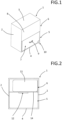
- a storage container 1 which is designed as a cabinet and has a body with side cheeks 2, a lid 3, a base 4 and a rear wall.
- the cabinet has a lower cabinet compartment 5 and an upper cabinet compartment 6 arranged above it.
- a watertight drawer which is open at the top and forms a storage tray 7 and is intended for charging accumulators, in particular lithium-based accumulators.
- the design of the storage tray 7 as a drawer enables quick and uncomplicated access from above to the contents of the lower cabinet compartment 5, for example if accumulators are to be placed in the drawer or removed from it and the storage tray is pulled out of the cabinet body for this purpose.
- the front of the cabinet is formed in the area of the lower cabinet compartment 5 by the drawer front of the storage tray 7.
- the cabinet front is designed as a removable panel 8 in view of the rarely required access to the upper cabinet compartment 6, although the front can also be designed as a pivoting door.
- the front of the storage tray 7 is provided with a handle 9. Furthermore, in the lower area of the storage tray 7, a drain valve 10 is schematically indicated on the front, which can optionally open or close an outlet opening of the storage tray 7. closes and, due to its deep arrangement on the storage trough 7, enables it to be largely emptied.
- Fig. 2 shows the storage container 1 after removing the cladding panel 8 and the storage tray 7.
- the upper cabinet compartment 6 contains an extinguishing agent container 11, which has been manufactured as a separate, prefabricated and commercially available container and is therefore economically available.
- the extinguishing agent container 11 does not completely fill the upper cabinet compartment 6. Rather, space remains as installation space for a residual current circuit breaker, an electronic control system and the like.
- a gate valve 12 which represents a valve that can optionally open a connection between the extinguishing agent container 11 and the lower cabinet compartment below it.
- This valve is basically closed and the connection is therefore impassable.
- no thermal actuation of the valve is provided, but rather an electrical actuation of the valve by a servomotor that is electrically controlled by means of the electronic control mentioned and that moves the gate valve 12 into its open position in the event of a fire.
- the electronic control is connected to a sensor that records the temperature prevailing in the upper area of the lower cabinet compartment 5.
- the lower cabinet compartment 5 is separated from the upper cabinet compartment 6 by a shelf 14.
- An opening in the shelf 14 creates the connection from an outlet opening of the extinguishing agent container 11 to the lower cabinet compartment 5.
- the capacity of the storage pan 7 is adapted to the extinguishing agent container. Assuming that the storage pan 7 is partially filled with material, the amount of extinguishing agent makes up about 80 to 90% of the capacity of the storage pan 7. In relation to the volume of the combustible material, the amount of extinguishing agent has a considerably larger volume than the material in order to ensure the desired cooling effect in the event of a fire.
- Fig. 3 shows a second embodiment of a storage container 1, which is also designed as a cupboard.
- the cupboard front is formed by a pivoting door 15, and the handle bar 9 is located on the side of the door 15 opposite the door hinge.
- the door 15 is connected to the furniture body in a watertight manner, so that together with the body it forms the storage tray 7 and in the event of a fire, if the lower cupboard compartment 5 has been flooded, the extinguishing agent can remain in the storage tray 7 for a longer period of time.
- This design of the storage tray 7 is also equipped with a drain valve 10, which is arranged in the lower area of the door 15.
- Fig. 4 shows that the structure of the storage container 1 is essentially the same as that of the first embodiment.
- the storage container 1 of the Fig. 3 has an extinguishing agent container 11 in the upper cabinet compartment 6, the connection of which to the lower cabinet compartment 5 is interrupted by a gate valve 12 that can be opened optionally.
- This storage container 1 also has an installation space in the upper cabinet compartment 6 in addition to the extinguishing agent container 11 for accommodating a residual current device, an electronic control system, a data modem or the like.
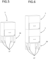
- Fig. 5 shows a storage container 1 which, in contrast to the embodiments of the Fig. 1 to 4 does not stand directly on the floor, but rather on a base 16 with four legs. This facilitates the handling of the accumulators, as they can be inserted into or removed from the respective storage tray 7 at an ergonomically favorable height.
- Fig. 6 shows two differences to the embodiments of the Fig. 1 to 4 : as in Fig. 5
- a storage container 1 stands on a base 16 with legs 17.
- Fig. 6 that two storage containers 1 can be stacked directly on top of each other.
- a single storage container 1 can also be designed in such a way that it has two or more storage trays 7 alternately one above the other and the extinguishing agent container 11 arranged above each one.
- the ratio between the combustible material and the amount of extinguishing agent can be kept so advantageous that the extinguishing agent can be fed into the respective storage tray in a volume that is considerably larger than the volume of the combustible material.
Landscapes
- Health & Medical Sciences (AREA)
- Public Health (AREA)
- Business, Economics & Management (AREA)
- Emergency Management (AREA)
- Fire-Extinguishing By Fire Departments, And Fire-Extinguishing Equipment And Control Thereof (AREA)
Applications Claiming Priority (1)
| Application Number | Priority Date | Filing Date | Title |
|---|---|---|---|
| DE202023104544.8U DE202023104544U1 (de) | 2023-08-10 | 2023-08-10 | Lagerungsbehälter |
Publications (1)
| Publication Number | Publication Date |
|---|---|
| EP4506039A1 true EP4506039A1 (fr) | 2025-02-12 |
Family
ID=88599410
Family Applications (1)
| Application Number | Title | Priority Date | Filing Date |
|---|---|---|---|
| EP24194210.1A Pending EP4506039A1 (fr) | 2023-08-10 | 2024-08-12 | Récipient de stockage |
Country Status (2)
| Country | Link |
|---|---|
| EP (1) | EP4506039A1 (fr) |
| DE (1) | DE202023104544U1 (fr) |
Citations (4)
| Publication number | Priority date | Publication date | Assignee | Title |
|---|---|---|---|---|
| DE2717497A1 (de) * | 1977-04-20 | 1978-10-26 | Horst Lemke | Selbstloeschender abfalleimer mit wasser als loeschmittel |
| CN206585226U (zh) * | 2017-03-21 | 2017-10-24 | 林宗灏 | 一种火灾预警的高压开关柜 |
| CN108853848A (zh) * | 2018-08-24 | 2018-11-23 | 东莞骑士换电电子科技有限公司 | 一种充电电池柜的消防水循环利用方法、系统和装置 |
| WO2021136875A1 (fr) * | 2019-12-30 | 2021-07-08 | Latauspolku Oy | Armoire de batterie et procédé de stockage en toute sécurité d'une batterie |
-
2023
- 2023-08-10 DE DE202023104544.8U patent/DE202023104544U1/de active Active
-
2024
- 2024-08-12 EP EP24194210.1A patent/EP4506039A1/fr active Pending
Patent Citations (4)
| Publication number | Priority date | Publication date | Assignee | Title |
|---|---|---|---|---|
| DE2717497A1 (de) * | 1977-04-20 | 1978-10-26 | Horst Lemke | Selbstloeschender abfalleimer mit wasser als loeschmittel |
| CN206585226U (zh) * | 2017-03-21 | 2017-10-24 | 林宗灏 | 一种火灾预警的高压开关柜 |
| CN108853848A (zh) * | 2018-08-24 | 2018-11-23 | 东莞骑士换电电子科技有限公司 | 一种充电电池柜的消防水循环利用方法、系统和装置 |
| WO2021136875A1 (fr) * | 2019-12-30 | 2021-07-08 | Latauspolku Oy | Armoire de batterie et procédé de stockage en toute sécurité d'une batterie |
Also Published As
| Publication number | Publication date |
|---|---|
| DE202023104544U1 (de) | 2023-10-17 |
Similar Documents
| Publication | Publication Date | Title |
|---|---|---|
| EP2076317B1 (fr) | Système d'extinction d'incendie destiné à un boîtier | |
| EP4374450A1 (fr) | Dispositif de protection pour accumulateur d'énergie | |
| EP1850445B1 (fr) | Point de chargement de batterie et procédé de fonctionnement et de fabrication correspondant | |
| DE202023101699U1 (de) | Behältnis zur Lagerung von Batterien sowie dessen Verwendung | |
| DE102019127014B4 (de) | Wannenförmiger Behälter zur Aufnahme von HV-Batterien und/oder E-Fahrzeugen und Verfahren zu dessen Betrieb | |
| EP3356630B1 (fr) | Coffret de sécurité | |
| DE202014101880U1 (de) | Kompakte Miniatur-Feuerlösch- bzw. Brandschutzeinrichtung | |
| DE102008059968A1 (de) | Verfahren und Vorrichtung zur Brandprävention und/oder -bekämpfung für eine Li-Ionen Batterie eines Fahrzeuges, insbesondere eines Kraftfahrzeuges | |
| WO2014023485A1 (fr) | Technologie d'extinction pour batteries à haute tension dans des véhicules hybrides ou électriques | |
| EP3885007B1 (fr) | Dispositif de détection d'incendie et de lutte contre l'incendie pour installations électriques | |
| EP3613472A2 (fr) | Système de protection incendie et méthode | |
| DE202021001906U1 (de) | Lagercontainer für Akkus | |
| DE102019108622A1 (de) | Aufnahmevorrichtung für einen Akku | |
| WO2019166336A1 (fr) | Dispositif de protection pour un boîtier de batterie de véhicule à moteur, batterie de traction et véhicule à moteur | |
| AT523904A2 (de) | Kompaktes Kühl- und Löschsystem | |
| EP4506039A1 (fr) | Récipient de stockage | |
| DE102012200075B3 (de) | Wäschetrockner mit selbsttätigem Feuerlöschsystem | |
| DE102020113475A1 (de) | Löschvorrichtung und Löschverfahren | |
| EP4182040B1 (fr) | Système de protection contre l'incendie pour la protection contre l'incendie de produits dangereux liquides et procédé correspondant | |
| DE102015008274A1 (de) | Stellantrieb mit einer Notenergieversorgungseinrichtung, Verfahren zu dessen Betrieb sowie Verwendung einer Notenergieversorgungseinrichtung an einem Stellantrieb | |
| EP4732363A1 (fr) | Dispositif de protection pour accumulateur d'énergie | |
| DE102015108546B4 (de) | Vorrichtung zum Auslassen einer in eine elektrische Vorrichtung eingedrungenen Flüssigkeit, elektrische Vorrichtung sowie Fahrzeug | |
| EP3357104A1 (fr) | Coffret de sécurité | |
| DE102012112564A1 (de) | Thermosensitives Steuerelement | |
| EP3420605B1 (fr) | Récipient |
Legal Events
| Date | Code | Title | Description |
|---|---|---|---|
| PUAI | Public reference made under article 153(3) epc to a published international application that has entered the european phase |
Free format text: ORIGINAL CODE: 0009012 |
|
| STAA | Information on the status of an ep patent application or granted ep patent |
Free format text: STATUS: THE APPLICATION HAS BEEN PUBLISHED |
|
| AK | Designated contracting states |
Kind code of ref document: A1 Designated state(s): AL AT BE BG CH CY CZ DE DK EE ES FI FR GB GR HR HU IE IS IT LI LT LU LV MC ME MK MT NL NO PL PT RO RS SE SI SK SM TR |
|
| STAA | Information on the status of an ep patent application or granted ep patent |
Free format text: STATUS: REQUEST FOR EXAMINATION WAS MADE |
|
| 17P | Request for examination filed |
Effective date: 20250306 |