EP4506054A1 - Dispositif de dépôt de poudre, installation de revêtement par poudre dotée d'une cabine de revêtement et d'un dispositif de dépôt de poudre ainsi que filtre conçu comme cartouche filtrante pour un tel dispositif de dépôt de poudre - Google Patents
Dispositif de dépôt de poudre, installation de revêtement par poudre dotée d'une cabine de revêtement et d'un dispositif de dépôt de poudre ainsi que filtre conçu comme cartouche filtrante pour un tel dispositif de dépôt de poudre Download PDFInfo
- Publication number
- EP4506054A1 EP4506054A1 EP24187131.8A EP24187131A EP4506054A1 EP 4506054 A1 EP4506054 A1 EP 4506054A1 EP 24187131 A EP24187131 A EP 24187131A EP 4506054 A1 EP4506054 A1 EP 4506054A1
- Authority
- EP
- European Patent Office
- Prior art keywords
- filter
- powder
- designed
- filter cartridge
- separation device
- Prior art date
- Legal status (The legal status is an assumption and is not a legal conclusion. Google has not performed a legal analysis and makes no representation as to the accuracy of the status listed.)
- Granted
Links
Images

Classifications
-
- B—PERFORMING OPERATIONS; TRANSPORTING
- B01—PHYSICAL OR CHEMICAL PROCESSES OR APPARATUS IN GENERAL
- B01D—SEPARATION
- B01D46/00—Filters or filtering processes specially modified for separating dispersed particles from gases or vapours
- B01D46/56—Filters or filtering processes specially modified for separating dispersed particles from gases or vapours with multiple filtering elements, characterised by their mutual disposition
- B01D46/58—Filters or filtering processes specially modified for separating dispersed particles from gases or vapours with multiple filtering elements, characterised by their mutual disposition connected in parallel
-
- B—PERFORMING OPERATIONS; TRANSPORTING
- B01—PHYSICAL OR CHEMICAL PROCESSES OR APPARATUS IN GENERAL
- B01D—SEPARATION
- B01D46/00—Filters or filtering processes specially modified for separating dispersed particles from gases or vapours
- B01D46/0002—Casings; Housings; Frame constructions
- B01D46/0005—Mounting of filtering elements within casings, housings or frames
- B01D46/0006—Filter elements or cartridges installed in a drawer-like manner
-
- B—PERFORMING OPERATIONS; TRANSPORTING
- B01—PHYSICAL OR CHEMICAL PROCESSES OR APPARATUS IN GENERAL
- B01D—SEPARATION
- B01D46/00—Filters or filtering processes specially modified for separating dispersed particles from gases or vapours
- B01D46/24—Particle separators, e.g. dust precipitators, using rigid hollow filter bodies
- B01D46/2403—Particle separators, e.g. dust precipitators, using rigid hollow filter bodies characterised by the physical shape or structure of the filtering element
- B01D46/2411—Filter cartridges
-
- B—PERFORMING OPERATIONS; TRANSPORTING
- B01—PHYSICAL OR CHEMICAL PROCESSES OR APPARATUS IN GENERAL
- B01D—SEPARATION
- B01D46/00—Filters or filtering processes specially modified for separating dispersed particles from gases or vapours
- B01D46/88—Replacing filter elements
-
- B—PERFORMING OPERATIONS; TRANSPORTING
- B05—SPRAYING OR ATOMISING IN GENERAL; APPLYING FLUENT MATERIALS TO SURFACES, IN GENERAL
- B05B—SPRAYING APPARATUS; ATOMISING APPARATUS; NOZZLES
- B05B14/00—Arrangements for collecting, re-using or eliminating excess spraying material
- B05B14/40—Arrangements for collecting, re-using or eliminating excess spraying material for use in spray booths
- B05B14/43—Arrangements for collecting, re-using or eliminating excess spraying material for use in spray booths by filtering the air charged with excess material
-
- B—PERFORMING OPERATIONS; TRANSPORTING
- B05—SPRAYING OR ATOMISING IN GENERAL; APPLYING FLUENT MATERIALS TO SURFACES, IN GENERAL
- B05B—SPRAYING APPARATUS; ATOMISING APPARATUS; NOZZLES
- B05B14/00—Arrangements for collecting, re-using or eliminating excess spraying material
- B05B14/40—Arrangements for collecting, re-using or eliminating excess spraying material for use in spray booths
- B05B14/48—Arrangements for collecting, re-using or eliminating excess spraying material for use in spray booths specially adapted for particulate material
-
- Y—GENERAL TAGGING OF NEW TECHNOLOGICAL DEVELOPMENTS; GENERAL TAGGING OF CROSS-SECTIONAL TECHNOLOGIES SPANNING OVER SEVERAL SECTIONS OF THE IPC; TECHNICAL SUBJECTS COVERED BY FORMER USPC CROSS-REFERENCE ART COLLECTIONS [XRACs] AND DIGESTS
- Y02—TECHNOLOGIES OR APPLICATIONS FOR MITIGATION OR ADAPTATION AGAINST CLIMATE CHANGE
- Y02P—CLIMATE CHANGE MITIGATION TECHNOLOGIES IN THE PRODUCTION OR PROCESSING OF GOODS
- Y02P70/00—Climate change mitigation technologies in the production process for final industrial or consumer products
- Y02P70/10—Greenhouse gas [GHG] capture, material saving, heat recovery or other energy efficient measures, e.g. motor control, characterised by manufacturing processes, e.g. for rolling metal or metal working
Definitions
- the present invention relates generally to the field of powder coating of articles.
- the invention relates to a powder coating system for powder coating objects in a coating booth, wherein the powder coating system has a powder separation device for separating powder from a powder-air mixture.
- the powder-air mixture is produced in particular in a coating operation of the powder coating system, and is generally raw gas (powder-air mixture) extracted from a coating booth of the powder coating system.
- the invention also relates in particular to a filter designed as a filter cartridge for such a powder separation device.
- Such a powder coating booth is known, for example, from the publication EP 0 839 583 A2 known.
- This is a vertically cylindrical cabin with a funnel-shaped cabin floor, which has a suction connection for an external suction source in the cabin center.
- a similar cylindrical powder coating booth is also known from the publication DE 195 00 872 A1 known.
- this powder coating booth has a channel-like floor edge along the booth wall, through which air and powder particles can also be extracted from the booth separately from the extraction flow of the extraction funnel.
- a slot extends diametrically through the floor plate, into which powder particles lying on the booth floor can be pushed by a rotating cleaning device.
- Spray coating powder is usually conveyed pneumatically to spray devices, so-called spray guns, and is sprayed pneumatically and with electrostatic support onto the objects to be coated.
- a small negative pressure is usually maintained in the powder coating booths during spray coating operations to prevent powder particles from escaping from the powder coating booth.
- the negative pressure usually maintained in the powder coating booths during spray coating operations also serves to extract excess powder, i.e. powder particles that bounce off the object or are sprayed past it.
- a powder separator for example in the form of a centrifugal separator (cyclone)
- a suction fan which is connected, for example, to an air outlet of the powder separator, sucks at least a large part of the excess powder and air from the interior of the powder coating booth through the powder separator.
- the extracted powder is separated from the suction air in the powder separator and transported further into a powder container, from which it can be fed together with fresh coating powder back into a spray device for spray coating objects in the powder coating booth.
- the air cleaned of the extracted excess powder in the powder separator passes through the suction fan either into the room atmosphere of the installation room of the powder coating booth or powder separator or to another filter system (post-filter), in which any powder particles still present in the air are separated.
- post-filter another filter system
- a cyclone or a cyclone system as a powder separator to separate powder from the extraction air.
- a cyclone system which is made up of one or more cyclones, for example, a suction fan sucks excess powder and air from the cabin interior through the cyclone system, whereby in the cyclone system the powder-air flow is separated into air and powder by cyclone centrifugal forces.
- the separated powder falls into a collecting container under the cyclone system, while the air, which is at least partially cleaned of powder, is usually blown into the outside atmosphere via a post-filter.
- Cyclone systems usually require such a post-filter because they cannot separate fine powder particles from the air flow as completely as would be the case with a filter system.
- the powder separated by the cyclone system is usually also processed and reused for spray coating.
- the powder separated from the post-filter is usually treated as waste.
- a post-filter commonly used in powder coating technology usually has several filter cartridges which are arranged in a raw gas chamber of the post-filter.
- the filters designed as filter cartridges are in flow connection with the raw gas (powder-air mixture) on one side, while another side of the filters designed as filter cartridges can be connected to a channel carrying clean gas or to a clean gas chamber.
- the filters designed as filter cartridges of a post-filter used in the field of powder coating of workpieces are often designed as lamella filters. However, other designs are also conceivable.
- the filters in the post-filter system which are designed as filter cartridges, are spare or wear parts that must be replaced regularly.
- the replaceable filter cartridges regularly used in post-filter systems usually have a cartridge flange which is detachably connected, in particular via a quick-release fastener, to a raw gas chamber of the post-filter.
- the filters designed as filter cartridges in particular have a structure as shown, for example, in the publication DE 11 2008 002 400 T5 is known.
- the filter cartridges are attached to the filter housing either by screwing them onto a filter cartridge flange or using a quick-release fastener.
- the flange is usually round in shape.
- the invention is based on the object of specifying a powder separation device for a powder coating system of the type described above, in which a change of the filters designed as filter cartridges can be implemented with the least possible time and effort.
- the invention relates in particular to a powder separation device for separating powder from a powder-air mixture, in particular from a powder mixture arising in a coating operation of a powder coating plant. and the powder-air mixture extracted from a coating booth of the coating system.
- the powder separation device has a housing which at least partially or regionally encloses a raw gas chamber and has a raw gas inlet which is or can be connected in terms of flow to a raw gas channel and a clean gas outlet.
- the powder separation device according to the invention has at least one filter which is arranged or to be arranged in the raw gas chamber and which is designed as a filter cartridge and which has a filter casing and a flange region connected to the filter casing.
- a guide system in particular in the form of a guide rail system, is formed in the housing of the powder separation device, which is designed to interact with the flange region of the filter designed as a filter cartridge in such a way that the filter designed as a filter cartridge can be inserted into the raw gas chamber in an insertion direction defined by the guide system.
- the filters to be replaced which are designed as filter cartridges, can be pushed into the corresponding insertion position, particularly from outside the housing of the powder separation device and specifically from outside the raw gas chamber of the powder separation device. This significantly reduces the time and effort required to replace the filters designed as filter cartridges of the powder separation device designed as a post-filter.
- the powder separation device has at least two filters, each designed as a filter cartridge, which are arranged in series one behind the other via the guide system and the corresponding flange areas at least two filters, each designed as a filter cartridge, can be inserted into or removed from the raw gas chamber in the insertion direction defined by the guide system.
- the guide system is assigned a locking device, in particular one that can be operated manually, via which the at least one filter designed as a filter cartridge can be locked in an inserted position inside the raw gas chamber as required.
- a flow channel enclosed by the filter casing of the at least one filter designed as a filter cartridge is fluidically connected to a clean gas chamber of the powder separation device.
- the guide system it is advisable for the guide system to have at least one guide associated with a bottom region of the clean gas line, wherein in an inserted position of the at least one filter designed as a filter cartridge, the at least one filter designed as a filter cartridge lies directly adjacent to a bottom opening of the clean gas line.
- the invention further relates to a powder coating system with a coating booth and a powder deposition device of the aforementioned type according to the invention.
- this is directed to a filter for a powder separation device.
- the powder separation device is in particular a powder separation device of the type according to the invention described above.
- the filter according to the invention is designed as a filter cartridge which has a filter casing enclosing a flow channel through which a powder-air mixture (raw gas) can flow and a flange region connected to the filter casing at an end region, in particular the upper end region, of the filter casing.
- the flange region is at least substantially rectangular in shape and has an opening, in particular arranged concentrically, which is at least partially or partially aligned coaxially with the flow channel through which the powder-air mixture (raw gas) can flow.
- the flange region of the filter according to the invention and designed as a filter cartridge is designed such that the filter designed as a filter cartridge can be inserted into a raw gas chamber of the powder separation device or pushed out of a raw gas chamber of the powder separation device via a guide system, in particular via a guide rail system.
- the flange area of the filter designed as a filter cartridge has two mutually opposite first side edges, which are designed at least partially or in regions to be complementary to guide rails of the guide system in such a way that over the two mutually opposite opposite first side edges of the flange area of the filter designed as a filter cartridge can be inserted into the raw gas chamber of the powder separation device.
- the flange region of the filter designed as a filter cartridge according to the present invention has two opposing second side edges, which each extend orthogonally to an insertion direction of the filter designed as a filter cartridge.
- a first side edge of the second side edges preferably has a first connecting element, while a second side edge of the second side edges has a second connecting element.
- the first connecting element is designed to be at least partially or regionally complementary to the second connecting element in such a way that a positive connection can be formed between the first and second connecting elements.
- the first connecting element is designed as an upwardly directed groove which extends over the entire length of a first side edge of the second side edges
- the second connecting element is designed as a downwardly directed groove which is complementary to the upwardly directed groove and extends over the entire length of a second side edge of the second side edges.
- the first connecting element has at least one projection formed in a first half of a first side edge of the second side edges and protruding from a front side of the first side edge and at least one receptacle formed in a second half of the first side edge of the second side edges and preferably complementary to the projection
- the second connecting element has at least one in a first half of a second Side edge of the second side edges and protruding from an end face of the second side edge and at least one receptacle formed in a second half of the second side edge of the second side edges and preferably complementary to the projection.
- handles, handle recesses or handle openings are formed in a region of the second side edges of the flange region of the filter.
- the opening of the flange region of the filter according to the invention designed as a filter cartridge which opening is arranged in particular concentrically, has a circumferential seal (sealing ring) which is designed in particular to seal a flow connection between the flow channel, which is enclosed by the filter casing of the filter, and an opening of a clean gas line of the powder separation device in an installation position or insertion position of the filter designed as a filter cartridge.
- a circumferential seal sealing ring
- the flange region is preferably formed from an electrically conductive material, in particular plastic material.
- the filter designed as a filter cartridge, it is provided that at least one receptacle or hole is formed in the flange area, wherein the at least one receptacle or the at least one hole is designed to receive a particularly pin-shaped clamping element at least partially or in some areas in a form-fitting manner for positioning the filter in an insertion position within the raw gas chamber of a powder separation device.
- FIG. 1 shows schematically an exemplary embodiment of a powder coating system 1 for spray coating objects 2 with coating powder, which is then FIG. 1 not shown heating furnace is melted onto the objects 2.
- One or more electronic control devices 3 are provided for controlling the function of the powder coating system 1.
- Powder pumps 4 are provided for pneumatic conveying of the coating powder. These can be powder injectors in which coating powder is sucked from a powder container by means of compressed air serving as conveying compressed air, after which the mixture of conveying compressed air and coating powder then flows together into a container or to a spray device.
- Suitable powder injectors are known, for example, from the publication EP 0 412 289 B1 known.
- the powder pump 4 can also be a type of pump that uses compressed air to convey small powder portions one after the other, whereby a small powder portion (amount of powder) is stored in a powder chamber and then pressed out of the powder chamber using compressed air. The compressed air remains behind the powder portion and pushes the powder portion in front of it.
- These types of pumps are sometimes referred to as compressed air push pumps or plug conveying pumps, since the compressed air pushes the stored powder portion in front of it through a pump outlet line like a plug.
- the invention is not limited to any of the above-mentioned types of powder pumps.
- a compressed air source 6 is provided, which is connected to the various devices via corresponding pressure adjustment elements 8, for example pressure regulators and/or valves.
- Fresh powder from a powder supplier is fed from a supplier container, which can be, for example, a small container 12, for example in the form of a dimensionally stable container or a sack with a powder quantity of, for example, between 10 and 50 kg, for example 25 kg, or, for example, a large container 14, for example also a dimensionally stable container or a sack, with a powder quantity between, for example, 100 kg and 1,000 kg, by means of a powder pump 4 in a fresh powder line 16 or 18 to a sieving device 10.
- the sieving device 10 can be provided with a vibrator.
- the terms "small container” and "large container” mean both "dimensionally stable container” and “non-dimensionally stable, flexible bag", unless specific reference is made to one or the other type of container.
- the coating powder sieved by the sieving device 10 is conveyed by gravity or preferably by a powder pump 4 via one or more powder feed lines 20, 20' through powder inlet openings 26, 26' into a powder chamber 22 of a dimensionally stable powder container 24.
- the volume of the powder chamber 22 is preferably significantly smaller than the volume of the small fresh powder container 12.
- the powder pump 4 of the at least one powder supply line 20, 20' to the powder container 24 is a compressed air push pump.
- the initial section of the powder supply line 20 can serve as a pump chamber into which powder sieved by the sieving device 10 falls through a valve, for example a pinch valve.
- the powder supply line 20 is separated from the sieving device 10 in terms of flow by closing the valve. The powder portion is then pushed through the powder supply line 20, 20' into the powder chamber 22 by means of compressed air.
- Powder pumps 4 for example powder injectors, are connected to one or preferably several powder outlet openings 36 of the powder container 24 for conveying coating powder through powder lines 38 to spray devices 40.
- the spray devices 40 can have spray nozzles or rotary atomizers for spraying the coating powder 42 onto the object 2 to be coated, which is preferably located in a coating booth 43.
- the powder outlet openings 36 can - as in FIG. 1 shown - in a wall of the powder container 24 which is opposite the wall in which the powder inlet openings 26, 26' are located. Alternatively, it is also conceivable for the powder outlet openings 36 to be arranged in a wall of the powder container 24 which is adjacent to the wall in which the powder inlet openings 26, 26' are located.
- the powder outlet openings 36 are preferably arranged near the bottom of the powder chamber 22.
- the powder chamber 22 preferably has a size which is in the range of a coating powder capacity between 1.0 kg and 12.0 kg, preferably between 2.0 kg and 8.0 kg.
- the size of the powder chamber 22 is preferably between 500 cm 3 and 30,000 cm 3 , preferably between 2,000 cm 3 and 20,000 cm 3 .
- the size of the powder chamber 22 is selected depending on the number of powder outlet openings 36 and the powder lines 38 connected thereto in such a way that continuous spray coating operation is possible, but the powder chamber 22 can be quickly cleaned during coating breaks for a powder change, preferably automatically.
- the powder chamber 22 can be provided with a fluidizing device 30 for fluidizing the coating powder held in the powder container 24.
- the fluidizing device 30 contains at least one fluidizing wall made of an open-pored material or a material provided with narrow holes, which is permeable to compressed air but not to coating powder.
- the fluidizing wall forms the bottom of the powder container 24 and is arranged between the powder chamber 22 and a fluidizing compressed air chamber.
- the fluidizing compressed air chamber should be connectable to the compressed air source 6 via a pressure setting element 8.
- Coating powder 42 which does not adhere to the object 2 to be coated is sucked as excess powder via an excess powder line or suction channel 44 by means of a suction air flow from a blower 170 into one of the two powder separators 121, 131 available here.
- the excess powder is separated from the suction air flow as far as possible in the respective powder separator 121, 131.
- the separated powder portion can then be passed as recovery powder from the respective powder separator 121, 131 via a powder recovery line 50 to the screening device 10, where it is the sieve device 10, either alone or mixed with fresh powder via the powder feed lines 20, 20' back into the powder chamber 22.
- a powder recovery line 50 In the FIG. 1 In the schematically illustrated embodiment, only the (first) powder separator designated by the reference number "121" is provided with a corresponding powder recovery line 50.
- a changeover device 111 is provided which is or can be connected in terms of flow to an extraction channel 44 of the powder coating booth 43.
- the changeover device 111 is designed to optionally connect the extraction channel 44 of the powder coating booth 43 in terms of flow to the inlet of a first raw gas line 120 or to the inlet of at least one further, second raw gas line 130.
- the first raw gas line 120 is assigned to the first powder separator 121 and the at least one second raw gas line 130 is assigned to at least one second powder separator 131.
- the powder recovery line 50 can be separated from the sieve device 10 and to direct the recovery powder into a waste container, as shown in FIG. 1 is shown schematically by a dashed line 51.
- the powder recovery line 50 can be provided with a switch 52 so that it does not need to be separated from the screening device 10, to which it can be connected alternatively to the screening device 10 or to a waste container.
- the powder container 24 can have one or more, for example two sensors S1 and/or S2, in order to control the supply of coating powder into the powder chamber 22 by means of the control unit 3 and the powder pumps 4 in the powder feed lines 20, 20'.
- the lower sensor S1 detects a lower powder level limit
- the upper sensor S2 detects an upper powder level limit.
- the lower end section 48-2 of the first powder separator 121 can be designed and used as a storage container for recovery powder and can be provided with one or more, for example two sensors S3 and/or S4, which are functionally connected to the control unit 3.
- This can, for example, automatically control the fresh powder supply through the Fresh powder feed lines 16 and 18 can be stopped as long as there is sufficient recovery powder in the first powder separator 121 to supply the powder chamber 22 with sufficient recovery powder through the sieving device 10, which is required for the spray coating operation by means of the spray devices 40. If there is no longer sufficient recovery powder in the first powder separator 121, it can be automatically switched to the supply of fresh powder through the fresh powder feed lines 16 or 18. It is also possible to supply fresh powder and recovery powder to the sieving device 10 at the same time so that they are mixed with one another.
- the exhaust air from the powder separators 121, 131 passes through an exhaust air line 54 into a post-filter device 56 and therein through one or more filter elements 58 to the blower 170 and then into the outside atmosphere.
- the filter elements 58 can be filter bags or filter cartridges or filter plates or similar filter elements.
- the powder separated from the air stream by means of the filter elements 58 is normally waste powder and falls into a waste container by gravity or can, as in FIG. 1 shown, are conveyed via one or more waste lines 60, each containing a powder pump 4, into a waste container 62 at a waste station 63.
- the waste powder can also be recovered to the sieve device 10 to be re-entered into the coating cycle.
- FIG. 1 schematically represented by switches 59 and branch lines 61 of the waste lines 60.
- powder separators 121, 131 and a post-filter device 56 are usually used and the waste powder from the post-filter device 56 ends up in the waste container 62.
- the powder separation efficiency of the powder separators 121, 131 is - at least when they are designed as centrifugal separators (cyclone separators) - usually lower than that of the post-filter device 56, but the changer device 111 can be used to switch between the powder separators 121, 131 depending on the type of powder.
- the powder separator designated with the reference number "121" is designed as a centrifugal separator (cyclone separator), to which a powder return system is also assigned.
- the powder separator 121 designed as a centrifugal separator is - as in FIG. 1 indicated schematically - connected downstream to a post-filter device 56, preferably designed as a plate or cartridge separator.
- the powder separator shown schematically and designated with the reference number "131" is designed, for example, as a plate or cartridge separator and is provided with a corresponding suction fan 170.
- This powder separator 131 designed as a plate or cartridge separator is also assigned a powder return system, as shown in FIG. 1 is indicated schematically.
- the lower end of at least the first powder separator 121 can have an outlet valve 64, for example a pinch valve. Furthermore, above this outlet valve 64, in or at the lower end of the lower end section 48-2 of the powder separator 121 designed as a storage container, a fluidizing device 66 for fluidizing the coating powder can be provided.
- the fluidizing device 66 contains at least one fluidizing wall 80 made of an open-pored material or a material provided with narrow holes, which is permeable to compressed air but not to coating powder.
- the fluidizing wall 80 is arranged between the powder path and a fluidizing compressed air chamber 81.
- the fluidizing compressed air chamber 81 can be connected to the compressed air source 6 via a pressure setting element 8.
- the fresh powder line 16 and/or 18 can be fluidly connected at its upstream end, either directly or through the powder pump 4, to a powder feed pipe 65 which can be immersed in the supplier container 12 or 14 for sucking off fresh coating powder.
- the powder pump 4 can be arranged at the beginning, at the end or in between in the fresh powder line 16 or 18 or at the upper or lower end of the powder feed pipe 65.
- FIG. 1 shows a fresh powder powder bag 12 in a bag receiving funnel 174 as a small fresh powder container.
- the powder bag 12 is held in a defined shape by the bag receiving funnel 174, with the bag opening located at the upper end of the bag.
- the bag receiving funnel 174 can be arranged on a scale or weighing sensors 176. Depending on the type, these scales or the weighing sensors 176 can generate an optical display and/or an electrical signal which, after deducting the weight of the bag receiving funnel 174, corresponds to the weight and thus also the amount of coating powder in the small container 12.
- At least one vibrating vibrator 178 is preferably arranged on the bag receiving funnel 174.
- Two or more small containers 12 can be provided in each bag receiving funnel 74 and/or two or more large containers 14 can be provided which can be used alternatively. This enables a quick change from one small container 12 or large container 14 to another.
- FIG. 1 Although in FIG. 1 not shown, it is basically conceivable that the sieving device 10 is integrated in the powder container 24.
- the sieving device 10 can be omitted if the fresh powder is of sufficiently good quality.
- the recovery powder also does not require a sieve if its powder quality is sufficiently good for reuse.
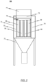
- FIG. 2 shows schematically in a side sectional view a post-filter, for example in the FIG. 1 powder separation device 56 used in the powder coating system 1 shown schematically.
- the powder separation device 56 shown schematically serves for separating powder from a powder-air mixture, in particular from a powder that is produced in a coating plant of a powder coating system 1 and powder-air mixture extracted from a coating booth 43 of the powder coating system 1.
- the powder separation device 56 has a housing 71 which at least partially or regionally encloses a raw gas chamber 70.
- the housing 71 is provided with a raw gas inlet that is or can be connected in terms of flow to a raw gas channel 75 and with a clean gas outlet.
- FIG. 2 It can also be seen that a plurality of filters, each designed as a filter cartridge 58, are arranged in the raw gas chamber 70. These filters, designed as filter cartridges 58, are arranged in the raw gas chamber 70 in a particularly exchangeable or replaceable manner.
- each filter designed as a filter cartridge 58 has a filter jacket 98 and a flange region 90 connected to the filter jacket 98.
- raw gas used here generally refers to the gas to be cleaned, i.e. the gas enriched with powder particles, typically air, which is to be filtered.
- clean gas used here generally refers to the filtered raw gas, which has passed through the filter or filters designed as filter cartridges 58 and has been at least partially freed of particles (powder particles).
- a guide system 76 designed in particular as a guide rail system, is provided in the housing 71 of the powder separation device 56, which is designed to interact with the flange region 90 of the filter designed as a filter cartridge 58 in such a way that the filter designed as a filter cartridge 58 can be inserted into the raw gas chamber 70 of the powder separation device 56 in an insertion direction defined by the guide system 76.
- the powder deposition device 56 according to the in FIG. 2 schematically shown embodiment, several filters each designed as a filter cartridge 58, which are arranged in series one behind the other via the guide system 76 and the corresponding flange areas 90 of the filters, each designed as a filter cartridge 58, can be inserted into the raw gas chamber 70, preferably manually, in the insertion direction defined by the guide system 76.
- the guide system 76 is assigned a locking device, in particular a manually operable one, by means of which the filters, each designed as a filter cartridge 58, can be locked in an inserted position inside the raw gas chamber 70 if required.
- the raw gas inlet is provided in an upper region of the raw gas chamber 70. Furthermore, the raw gas chamber 70 has a powder outlet arranged in a lower region of the raw gas chamber 70 and connected or connectable in terms of flow to a discharge funnel 72.
- Each filter designed as a filter cartridge 58 has a flow channel 97 which is enclosed by the filter casing 98 of the corresponding filter designed as a filter cartridge 58 and which, in an inserted position of the corresponding filter designed as a filter cartridge 58, is fluidically connected to a clean gas chamber 74 of the powder separation device 56.
- each filter designed as a filter cartridge 58 is fluidly connected to a clean gas line 73 running through the raw gas chamber 70, which is open in particular at the top and bottom, wherein the clean gas line 73 opens into the already mentioned clean gas chamber 74, which in the embodiment of the powder separation device 56 shown is laterally adjacent to the raw gas chamber 70.
- the guide system 76 has at least one guide associated with a bottom region of the clean gas line 73.
- each filter designed as a filter cartridge 58 lies directly adjacent to a bottom opening of the clean gas line 73.
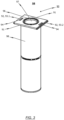
- the filter is particularly suitable for a powder separation device 56, as described in the exemplary embodiment in FIG. 2 previously described.
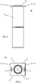
- the filter is designed as a filter cartridge 58 extending in a vertical direction, which has a filter casing 98 enclosing a flow channel 97 through which a powder-air mixture (raw gas) can flow, and a flange region 90 connected to the filter casing 98 at an end region, in particular the upper end region, of the filter casing 98.
- the flange region 90 is at least substantially rectangular and has a particularly concentrically arranged opening 95 which is at least partially or partially coaxial with the flow channel 97 through which the powder-air mixture (raw gas) can flow and which is enclosed by the filter casing 98 of the filter.
- the flange region 90 of the filter designed as a filter cartridge 58 is designed such that the filter designed as a filter cartridge 58 can be inserted, in particular manually, into a raw gas chamber 70 of the powder separation device 56 via a guide system 76.
- the flange region 90 of the filter designed as a filter cartridge 58 has two mutually opposite first side edges 91 which are designed to be at least partially or regionally complementary to guide rails of the guide system 76 of the powder separation device 56 in such a way that the filter designed as a filter cartridge 58 can be pushed into the raw gas chamber 70 of the powder separation device 56, in particular manually, via the two mutually opposite first side edges 91 of the flange region 90.
- the flange area 90 of the filter designed as a filter cartridge 58 has two opposite second side edges 92, which each extend orthogonally to an insertion direction of the filter designed as a filter cartridge 58.
- a first side edge of the second side edges 92 has a first connecting element 93.1 or is formed as a first connecting element 93.1, wherein a second side edge of the second side edges 92 has a second connecting element 93.2 or is formed as a second connecting element 93.2.
- the first connecting element 93.1 is designed to be at least partially or regionally complementary to the second connecting element 93.2 in such a way that a positive connection can be formed between the first and second connecting elements 93.1, 93.2.
- handle recesses 94 or handle openings are formed in a region of the second side edges 92 of the flange region 90 of the filter designed as a filter cartridge 58.
- the opening 95 of the flange region 90 which is arranged in particular concentrically, has a circumferential seal 96, in particular a ring seal, which is designed in particular to seal a flow connection between the flow channel 97 of the filter designed as a filter cartridge 58, which is enclosed by the filter casing 98 of the filter, and an opening of a clean gas line 73 of the powder separation device 56 in an installation position or insertion position of the filter designed as a filter cartridge 58.
Landscapes
- Chemical & Material Sciences (AREA)
- Chemical Kinetics & Catalysis (AREA)
- Physics & Mathematics (AREA)
- Geometry (AREA)
- Filtering Of Dispersed Particles In Gases (AREA)
- Details Or Accessories Of Spraying Plant Or Apparatus (AREA)
Applications Claiming Priority (1)
| Application Number | Priority Date | Filing Date | Title |
|---|---|---|---|
| DE102023120925.6A DE102023120925A1 (de) | 2023-08-07 | 2023-08-07 | Pulverabscheidungsvorrichtung, pulverbeschichtungsanlage mit einer beschichtungskabine und einer pulverabscheidungsvorrichtung sowie als filterpatrone ausgeführter filter für eine solche pulverabscheidungsvorrichtung |
Publications (2)
| Publication Number | Publication Date |
|---|---|
| EP4506054A1 true EP4506054A1 (fr) | 2025-02-12 |
| EP4506054B1 EP4506054B1 (fr) | 2025-10-22 |
Family
ID=91898563
Family Applications (1)
| Application Number | Title | Priority Date | Filing Date |
|---|---|---|---|
| EP24187131.8A Active EP4506054B1 (fr) | 2023-08-07 | 2024-07-08 | Dispositif de dépôt de poudre, installation de revêtement par poudre dotée d'une cabine de revêtement et d'un dispositif de dépôt de poudre ainsi que filtre conçu comme cartouche filtrante pour un tel dispositif de dépôt de poudre |
Country Status (2)
| Country | Link |
|---|---|
| EP (1) | EP4506054B1 (fr) |
| DE (1) | DE102023120925A1 (fr) |
Citations (17)
| Publication number | Priority date | Publication date | Assignee | Title |
|---|---|---|---|---|
| EP0338314A1 (fr) * | 1988-04-20 | 1989-10-25 | Nordson Corporation | Dispositif de récupération de poudre pour installations de revêtement par poudre ou similaires |
| US5002594A (en) * | 1989-08-31 | 1991-03-26 | Ransburg Corporation | Filter pulse-down cartridge cleaning mechanism |
| EP0412289B1 (fr) | 1989-08-11 | 1993-10-27 | ITW Gema AG | Dispositif de pulvérisation électrostatique |
| DE19500872A1 (de) | 1995-01-13 | 1996-07-18 | Gema Volstatic Ag | Sprühbeschichtungsvorrichtung |
| EP0839583A2 (fr) | 1996-11-02 | 1998-05-06 | ITW Gema AG | Dispositif de revêtement d'objects par pulvérisation. |
| US5961696A (en) * | 1993-10-25 | 1999-10-05 | Airotech, Inc. | Method of and apparatus for installing filter cartridges in a dust collector |
| DE19837877A1 (de) | 1998-08-20 | 2000-02-24 | Erich Kraemer | Pulverbeschichtungsanlage |
| US20020020160A1 (en) * | 2000-08-12 | 2002-02-21 | Moore Stephen H. | Cartridge dust collector |
| US6508610B2 (en) | 1999-12-10 | 2003-01-21 | Frederic Dietrich | Apparatus and method of pneumatically conveying powder substances and use of the apparatus |
| DE10145448A1 (de) | 2001-09-14 | 2003-05-22 | Bayerische Motoren Werke Ag | Vorrichtung zum Fördern von Pulver und Verfahren zu deren Betrieb |
| WO2005051549A1 (fr) | 2003-11-24 | 2005-06-09 | Nordson Corporation | Pompe a phase dense pour matiere particulaire seche |
| DE10353968A1 (de) | 2003-11-19 | 2005-07-07 | Itw Gema Ag | Beschichtungspulver-Fördervorrichtung und -Förderverfahren |
| US20060193704A1 (en) | 2003-07-11 | 2006-08-31 | Giancarlo Simontacchi | Device for conveying powders through pipelines |
| DE102007005310A1 (de) * | 2007-02-02 | 2008-08-07 | Itw Gema Ag | Beschichtungspulver-Filtervorrichtung |
| DE112008002400T5 (de) | 2007-09-05 | 2010-08-05 | Cummins Filtration IP, Inc., Minneapolis | Austauschbare Filterelemente einschließlich einzigartiger Schnittstellen und Filtrationsanlagen, die gleiches umfassen |
| US20190255476A1 (en) * | 2018-02-22 | 2019-08-22 | Lincoln Global, Inc. | Dust collector |
| US20190374892A1 (en) * | 2018-06-11 | 2019-12-12 | Imperial Systems, Inc. | Cartridges for Vertically Oriented Dust Collectors |
Family Cites Families (1)
| Publication number | Priority date | Publication date | Assignee | Title |
|---|---|---|---|---|
| DE10258526A1 (de) * | 2002-12-14 | 2004-07-08 | Schlick, Jennifer, Dipl.-Ing. (FH) | Filtereinrichtung |
-
2023
- 2023-08-07 DE DE102023120925.6A patent/DE102023120925A1/de active Pending
-
2024
- 2024-07-08 EP EP24187131.8A patent/EP4506054B1/fr active Active
Patent Citations (17)
| Publication number | Priority date | Publication date | Assignee | Title |
|---|---|---|---|---|
| EP0338314A1 (fr) * | 1988-04-20 | 1989-10-25 | Nordson Corporation | Dispositif de récupération de poudre pour installations de revêtement par poudre ou similaires |
| EP0412289B1 (fr) | 1989-08-11 | 1993-10-27 | ITW Gema AG | Dispositif de pulvérisation électrostatique |
| US5002594A (en) * | 1989-08-31 | 1991-03-26 | Ransburg Corporation | Filter pulse-down cartridge cleaning mechanism |
| US5961696A (en) * | 1993-10-25 | 1999-10-05 | Airotech, Inc. | Method of and apparatus for installing filter cartridges in a dust collector |
| DE19500872A1 (de) | 1995-01-13 | 1996-07-18 | Gema Volstatic Ag | Sprühbeschichtungsvorrichtung |
| EP0839583A2 (fr) | 1996-11-02 | 1998-05-06 | ITW Gema AG | Dispositif de revêtement d'objects par pulvérisation. |
| DE19837877A1 (de) | 1998-08-20 | 2000-02-24 | Erich Kraemer | Pulverbeschichtungsanlage |
| US6508610B2 (en) | 1999-12-10 | 2003-01-21 | Frederic Dietrich | Apparatus and method of pneumatically conveying powder substances and use of the apparatus |
| US20020020160A1 (en) * | 2000-08-12 | 2002-02-21 | Moore Stephen H. | Cartridge dust collector |
| DE10145448A1 (de) | 2001-09-14 | 2003-05-22 | Bayerische Motoren Werke Ag | Vorrichtung zum Fördern von Pulver und Verfahren zu deren Betrieb |
| US20060193704A1 (en) | 2003-07-11 | 2006-08-31 | Giancarlo Simontacchi | Device for conveying powders through pipelines |
| DE10353968A1 (de) | 2003-11-19 | 2005-07-07 | Itw Gema Ag | Beschichtungspulver-Fördervorrichtung und -Förderverfahren |
| WO2005051549A1 (fr) | 2003-11-24 | 2005-06-09 | Nordson Corporation | Pompe a phase dense pour matiere particulaire seche |
| DE102007005310A1 (de) * | 2007-02-02 | 2008-08-07 | Itw Gema Ag | Beschichtungspulver-Filtervorrichtung |
| DE112008002400T5 (de) | 2007-09-05 | 2010-08-05 | Cummins Filtration IP, Inc., Minneapolis | Austauschbare Filterelemente einschließlich einzigartiger Schnittstellen und Filtrationsanlagen, die gleiches umfassen |
| US20190255476A1 (en) * | 2018-02-22 | 2019-08-22 | Lincoln Global, Inc. | Dust collector |
| US20190374892A1 (en) * | 2018-06-11 | 2019-12-12 | Imperial Systems, Inc. | Cartridges for Vertically Oriented Dust Collectors |
Also Published As
| Publication number | Publication date |
|---|---|
| DE102023120925A1 (de) | 2025-02-13 |
| EP4506054B1 (fr) | 2025-10-22 |
Similar Documents
| Publication | Publication Date | Title |
|---|---|---|
| EP0044310B2 (fr) | Installation de revetement de pieces d'oeuvre par poudre comportant une cabine pour recevoir temporairement la piece d'oeuvre | |
| DE102010039473B4 (de) | Pulverversorgungsvorrichtung für eine Pulverbeschichtungsanlage | |
| DE69829571T2 (de) | Verbesserungen zur pulversprühbeschichtung | |
| DE4134701C2 (de) | Pulver-Sprühbeschichtungseinrichtung mit alternativ austauschbaren Filter- und Zykloneinheiten | |
| EP0141778B1 (fr) | Installation puor le revêtement électrostatique par poudre | |
| DE102010025749B4 (de) | Pulverversorgungsvorrichtung für eine Pulverbeschichtungsanlage | |
| DE102007005306B4 (de) | Pulverzufuhrvorrichtung von einer Pulversprühbeschichtungsanlage | |
| DE102007005312A1 (de) | Pulverrückgewinnungsvorrichtung für eine Pulversprühbeschichtungsanlage | |
| DE3135898A1 (de) | "verfahren und vorrichtung zum beschichten von gegenstaenden" | |
| EP1952892B1 (fr) | Installation de revêtement par poudre vaporisée et procédé de revêtement par poudre vaporisée | |
| DE3704551C1 (en) | Spray coating system | |
| EP0606577A1 (fr) | Dispositif de revêtement de poudre par pulverisation | |
| AT401389B (de) | Pulver-sprühbeschichtungsvorrichtung | |
| DE2546920B2 (de) | Elektrostatische pulver-beschichtungsanlage | |
| DE4300837A1 (de) | Pulver-Sprühbeschichtungsanlage | |
| EP3277435B1 (fr) | Dispositif de distribution d'un melange poudre-air | |
| DE19500872B4 (de) | Pulver-Sprühbeschichtungsvorrichtung | |
| DE102008056369A1 (de) | Zyklonabscheider und Pulverrückgewinnungsvorrichtung für eine Pulverbeschichtungsanlage mit einem Zyklonabscheider | |
| EP3148709B1 (fr) | Cabine de pulvérisation de poudre | |
| EP4506054B1 (fr) | Dispositif de dépôt de poudre, installation de revêtement par poudre dotée d'une cabine de revêtement et d'un dispositif de dépôt de poudre ainsi que filtre conçu comme cartouche filtrante pour un tel dispositif de dépôt de poudre | |
| EP3218117B1 (fr) | Chambre à poudre pour une installation de revêtement par poudrage | |
| EP1080789A1 (fr) | Unité de récupération de poudre | |
| EP1342506A1 (fr) | Cabine de poudrage | |
| EP4676654A1 (fr) | Système de séparateur de poudre pour une installation de revêtement en poudre, installation de revêtement en poudre comprenant un tel système de séparateur de poudre, et procédé de fonctionnement d'une telle installation de revêtement en poudre | |
| DE8907540U1 (de) | Kabine zum Sprühbeschichten von Gegenständen mit pulverförmigem Beschichtungsmaterial |
Legal Events
| Date | Code | Title | Description |
|---|---|---|---|
| PUAI | Public reference made under article 153(3) epc to a published international application that has entered the european phase |
Free format text: ORIGINAL CODE: 0009012 |
|
| STAA | Information on the status of an ep patent application or granted ep patent |
Free format text: STATUS: REQUEST FOR EXAMINATION WAS MADE |
|
| 17P | Request for examination filed |
Effective date: 20240708 |
|
| AK | Designated contracting states |
Kind code of ref document: A1 Designated state(s): AL AT BE BG CH CY CZ DE DK EE ES FI FR GB GR HR HU IE IS IT LI LT LU LV MC ME MK MT NL NO PL PT RO RS SE SI SK SM TR |
|
| STAA | Information on the status of an ep patent application or granted ep patent |
Free format text: STATUS: EXAMINATION IS IN PROGRESS |
|
| GRAP | Despatch of communication of intention to grant a patent |
Free format text: ORIGINAL CODE: EPIDOSNIGR1 |
|
| STAA | Information on the status of an ep patent application or granted ep patent |
Free format text: STATUS: GRANT OF PATENT IS INTENDED |
|
| 17Q | First examination report despatched |
Effective date: 20250613 |
|
| INTG | Intention to grant announced |
Effective date: 20250710 |
|
| GRAS | Grant fee paid |
Free format text: ORIGINAL CODE: EPIDOSNIGR3 |
|
| GRAA | (expected) grant |
Free format text: ORIGINAL CODE: 0009210 |
|
| STAA | Information on the status of an ep patent application or granted ep patent |
Free format text: STATUS: THE PATENT HAS BEEN GRANTED |
|
| AK | Designated contracting states |
Kind code of ref document: B1 Designated state(s): AL AT BE BG CH CY CZ DE DK EE ES FI FR GB GR HR HU IE IS IT LI LT LU LV MC ME MK MT NL NO PL PT RO RS SE SI SK SM TR |
|
| REG | Reference to a national code |
Ref country code: CH Ref legal event code: F10 Free format text: ST27 STATUS EVENT CODE: U-0-0-F10-F00 (AS PROVIDED BY THE NATIONAL OFFICE) Effective date: 20251022 Ref country code: GB Ref legal event code: FG4D Free format text: NOT ENGLISH |
|
| REG | Reference to a national code |
Ref country code: DE Ref legal event code: R096 Ref document number: 502024000322 Country of ref document: DE |
|
| REG | Reference to a national code |
Ref country code: IE Ref legal event code: FG4D Free format text: LANGUAGE OF EP DOCUMENT: GERMAN |
|
| P01 | Opt-out of the competence of the unified patent court (upc) registered |
Free format text: CASE NUMBER: UPC_APP_0011295_4506054/2025 Effective date: 20251028 |
|
| REG | Reference to a national code |
Ref country code: NL Ref legal event code: MP Effective date: 20251022 |
|
| PG25 | Lapsed in a contracting state [announced via postgrant information from national office to epo] |
Ref country code: NL Free format text: LAPSE BECAUSE OF FAILURE TO SUBMIT A TRANSLATION OF THE DESCRIPTION OR TO PAY THE FEE WITHIN THE PRESCRIBED TIME-LIMIT Effective date: 20251022 |
|
| PG25 | Lapsed in a contracting state [announced via postgrant information from national office to epo] |
Ref country code: ES Free format text: LAPSE BECAUSE OF FAILURE TO SUBMIT A TRANSLATION OF THE DESCRIPTION OR TO PAY THE FEE WITHIN THE PRESCRIBED TIME-LIMIT Effective date: 20251022 |
|
| REG | Reference to a national code |
Ref country code: LT Ref legal event code: MG9D |
|
| PG25 | Lapsed in a contracting state [announced via postgrant information from national office to epo] |
Ref country code: NO Free format text: LAPSE BECAUSE OF FAILURE TO SUBMIT A TRANSLATION OF THE DESCRIPTION OR TO PAY THE FEE WITHIN THE PRESCRIBED TIME-LIMIT Effective date: 20260122 |
|
| PG25 | Lapsed in a contracting state [announced via postgrant information from national office to epo] |
Ref country code: HR Free format text: LAPSE BECAUSE OF FAILURE TO SUBMIT A TRANSLATION OF THE DESCRIPTION OR TO PAY THE FEE WITHIN THE PRESCRIBED TIME-LIMIT Effective date: 20251022 Ref country code: FI Free format text: LAPSE BECAUSE OF FAILURE TO SUBMIT A TRANSLATION OF THE DESCRIPTION OR TO PAY THE FEE WITHIN THE PRESCRIBED TIME-LIMIT Effective date: 20251022 |
|
| PG25 | Lapsed in a contracting state [announced via postgrant information from national office to epo] |
Ref country code: RS Free format text: LAPSE BECAUSE OF FAILURE TO SUBMIT A TRANSLATION OF THE DESCRIPTION OR TO PAY THE FEE WITHIN THE PRESCRIBED TIME-LIMIT Effective date: 20260122 |
|
| PG25 | Lapsed in a contracting state [announced via postgrant information from national office to epo] |
Ref country code: IS Free format text: LAPSE BECAUSE OF FAILURE TO SUBMIT A TRANSLATION OF THE DESCRIPTION OR TO PAY THE FEE WITHIN THE PRESCRIBED TIME-LIMIT Effective date: 20260222 |