EP4506067A1 - Procédé de formation de couche de revêtement de surface et procédé de production de joint - Google Patents
Procédé de formation de couche de revêtement de surface et procédé de production de joint Download PDFInfo
- Publication number
- EP4506067A1 EP4506067A1 EP23784679.5A EP23784679A EP4506067A1 EP 4506067 A1 EP4506067 A1 EP 4506067A1 EP 23784679 A EP23784679 A EP 23784679A EP 4506067 A1 EP4506067 A1 EP 4506067A1
- Authority
- EP
- European Patent Office
- Prior art keywords
- gasket
- fine particles
- temperature
- time period
- cleaning
- Prior art date
- Legal status (The legal status is an assumption and is not a legal conclusion. Google has not performed a legal analysis and makes no representation as to the accuracy of the status listed.)
- Pending
Links
Images




Classifications
-
- F—MECHANICAL ENGINEERING; LIGHTING; HEATING; WEAPONS; BLASTING
- F16—ENGINEERING ELEMENTS AND UNITS; GENERAL MEASURES FOR PRODUCING AND MAINTAINING EFFECTIVE FUNCTIONING OF MACHINES OR INSTALLATIONS; THERMAL INSULATION IN GENERAL
- F16J—PISTONS; CYLINDERS; SEALINGS
- F16J1/00—Pistons; Trunk pistons; Plungers
- F16J1/01—Pistons; Trunk pistons; Plungers characterised by the use of particular materials
-
- A—HUMAN NECESSITIES
- A61—MEDICAL OR VETERINARY SCIENCE; HYGIENE
- A61M—DEVICES FOR INTRODUCING MEDIA INTO, OR ONTO, THE BODY; DEVICES FOR TRANSDUCING BODY MEDIA OR FOR TAKING MEDIA FROM THE BODY; DEVICES FOR PRODUCING OR ENDING SLEEP OR STUPOR
- A61M5/00—Devices for bringing media into the body in a subcutaneous, intra-vascular or intramuscular way; Accessories therefor, e.g. filling or cleaning devices, arm-rests
- A61M5/178—Syringes
- A61M5/31—Details
- A61M5/315—Pistons; Piston-rods; Guiding, blocking or restricting the movement of the rod or piston; Appliances on the rod for facilitating dosing ; Dosing mechanisms
-
- A—HUMAN NECESSITIES
- A61—MEDICAL OR VETERINARY SCIENCE; HYGIENE
- A61M—DEVICES FOR INTRODUCING MEDIA INTO, OR ONTO, THE BODY; DEVICES FOR TRANSDUCING BODY MEDIA OR FOR TAKING MEDIA FROM THE BODY; DEVICES FOR PRODUCING OR ENDING SLEEP OR STUPOR
- A61M5/00—Devices for bringing media into the body in a subcutaneous, intra-vascular or intramuscular way; Accessories therefor, e.g. filling or cleaning devices, arm-rests
- A61M5/178—Syringes
- A61M5/31—Details
- A61M5/315—Pistons; Piston-rods; Guiding, blocking or restricting the movement of the rod or piston; Appliances on the rod for facilitating dosing ; Dosing mechanisms
- A61M5/31511—Piston or piston-rod constructions, e.g. connection of piston with piston-rod
- A61M5/31513—Piston constructions to improve sealing or sliding
-
- C—CHEMISTRY; METALLURGY
- C09—DYES; PAINTS; POLISHES; NATURAL RESINS; ADHESIVES; COMPOSITIONS NOT OTHERWISE PROVIDED FOR; APPLICATIONS OF MATERIALS NOT OTHERWISE PROVIDED FOR
- C09D—COATING COMPOSITIONS, e.g. PAINTS, VARNISHES OR LACQUERS; FILLING PASTES; CHEMICAL PAINT OR INK REMOVERS; INKS; CORRECTING FLUIDS; WOODSTAINS; PASTES OR SOLIDS FOR COLOURING OR PRINTING; USE OF MATERIALS THEREFOR
- C09D183/00—Coating compositions based on macromolecular compounds obtained by reactions forming in the main chain of the macromolecule a linkage containing silicon, with or without sulfur, nitrogen, oxygen, or carbon only; Coating compositions based on derivatives of such polymers
- C09D183/04—Polysiloxanes
-
- C—CHEMISTRY; METALLURGY
- C09—DYES; PAINTS; POLISHES; NATURAL RESINS; ADHESIVES; COMPOSITIONS NOT OTHERWISE PROVIDED FOR; APPLICATIONS OF MATERIALS NOT OTHERWISE PROVIDED FOR
- C09D—COATING COMPOSITIONS, e.g. PAINTS, VARNISHES OR LACQUERS; FILLING PASTES; CHEMICAL PAINT OR INK REMOVERS; INKS; CORRECTING FLUIDS; WOODSTAINS; PASTES OR SOLIDS FOR COLOURING OR PRINTING; USE OF MATERIALS THEREFOR
- C09D5/00—Coating compositions, e.g. paints, varnishes or lacquers, characterised by their physical nature or the effects produced; Filling pastes
-
- C—CHEMISTRY; METALLURGY
- C09—DYES; PAINTS; POLISHES; NATURAL RESINS; ADHESIVES; COMPOSITIONS NOT OTHERWISE PROVIDED FOR; APPLICATIONS OF MATERIALS NOT OTHERWISE PROVIDED FOR
- C09D—COATING COMPOSITIONS, e.g. PAINTS, VARNISHES OR LACQUERS; FILLING PASTES; CHEMICAL PAINT OR INK REMOVERS; INKS; CORRECTING FLUIDS; WOODSTAINS; PASTES OR SOLIDS FOR COLOURING OR PRINTING; USE OF MATERIALS THEREFOR
- C09D7/00—Features of coating compositions, not provided for in group C09D5/00; Processes for incorporating ingredients in coating compositions
- C09D7/40—Additives
- C09D7/65—Additives macromolecular
-
- C—CHEMISTRY; METALLURGY
- C09—DYES; PAINTS; POLISHES; NATURAL RESINS; ADHESIVES; COMPOSITIONS NOT OTHERWISE PROVIDED FOR; APPLICATIONS OF MATERIALS NOT OTHERWISE PROVIDED FOR
- C09D—COATING COMPOSITIONS, e.g. PAINTS, VARNISHES OR LACQUERS; FILLING PASTES; CHEMICAL PAINT OR INK REMOVERS; INKS; CORRECTING FLUIDS; WOODSTAINS; PASTES OR SOLIDS FOR COLOURING OR PRINTING; USE OF MATERIALS THEREFOR
- C09D7/00—Features of coating compositions, not provided for in group C09D5/00; Processes for incorporating ingredients in coating compositions
- C09D7/40—Additives
- C09D7/66—Additives characterised by particle size
- C09D7/69—Particle size larger than 1000 nm
-
- A—HUMAN NECESSITIES
- A61—MEDICAL OR VETERINARY SCIENCE; HYGIENE
- A61M—DEVICES FOR INTRODUCING MEDIA INTO, OR ONTO, THE BODY; DEVICES FOR TRANSDUCING BODY MEDIA OR FOR TAKING MEDIA FROM THE BODY; DEVICES FOR PRODUCING OR ENDING SLEEP OR STUPOR
- A61M5/00—Devices for bringing media into the body in a subcutaneous, intra-vascular or intramuscular way; Accessories therefor, e.g. filling or cleaning devices, arm-rests
- A61M5/178—Syringes
- A61M5/31—Details
- A61M5/3129—Syringe barrels
- A61M2005/3131—Syringe barrels specially adapted for improving sealing or sliding
-
- A—HUMAN NECESSITIES
- A61—MEDICAL OR VETERINARY SCIENCE; HYGIENE
- A61M—DEVICES FOR INTRODUCING MEDIA INTO, OR ONTO, THE BODY; DEVICES FOR TRANSDUCING BODY MEDIA OR FOR TAKING MEDIA FROM THE BODY; DEVICES FOR PRODUCING OR ENDING SLEEP OR STUPOR
- A61M2205/00—General characteristics of the apparatus
- A61M2205/02—General characteristics of the apparatus characterised by a particular materials
- A61M2205/0222—Materials for reducing friction
-
- A—HUMAN NECESSITIES
- A61—MEDICAL OR VETERINARY SCIENCE; HYGIENE
- A61M—DEVICES FOR INTRODUCING MEDIA INTO, OR ONTO, THE BODY; DEVICES FOR TRANSDUCING BODY MEDIA OR FOR TAKING MEDIA FROM THE BODY; DEVICES FOR PRODUCING OR ENDING SLEEP OR STUPOR
- A61M2205/00—General characteristics of the apparatus
- A61M2205/02—General characteristics of the apparatus characterised by a particular materials
- A61M2205/0238—General characteristics of the apparatus characterised by a particular materials the material being a coating or protective layer
-
- A—HUMAN NECESSITIES
- A61—MEDICAL OR VETERINARY SCIENCE; HYGIENE
- A61M—DEVICES FOR INTRODUCING MEDIA INTO, OR ONTO, THE BODY; DEVICES FOR TRANSDUCING BODY MEDIA OR FOR TAKING MEDIA FROM THE BODY; DEVICES FOR PRODUCING OR ENDING SLEEP OR STUPOR
- A61M2207/00—Methods of manufacture, assembly or production
- A61M2207/10—Device therefor
-
- B—PERFORMING OPERATIONS; TRANSPORTING
- B05—SPRAYING OR ATOMISING IN GENERAL; APPLYING FLUENT MATERIALS TO SURFACES, IN GENERAL
- B05D—PROCESSES FOR APPLYING FLUENT MATERIALS TO SURFACES, IN GENERAL
- B05D2201/00—Polymeric substrate or laminate
-
- B—PERFORMING OPERATIONS; TRANSPORTING
- B05—SPRAYING OR ATOMISING IN GENERAL; APPLYING FLUENT MATERIALS TO SURFACES, IN GENERAL
- B05D—PROCESSES FOR APPLYING FLUENT MATERIALS TO SURFACES, IN GENERAL
- B05D5/00—Processes for applying liquids or other fluent materials to surfaces to obtain special surface effects, finishes or structures
- B05D5/08—Processes for applying liquids or other fluent materials to surfaces to obtain special surface effects, finishes or structures to obtain an anti-friction or anti-adhesive surface
Definitions
- the present invention relates to a surface coating layer formation method and a gasket manufacturing method.
- a prefilled syringe filled with a liquid medicine in advance has been used.
- the prefilled syringe (hereinafter, referred to as a syringe) includes an outer barrel, a gasket, a plunger, and a cap.
- the gasket prevents leakage of the liquid medicine.
- it has been proposed to increase slidability (namely, to reduce sliding resistance) of the gasket in the outer barrel, for example, by coating a surface of the gasket with a coating film composed of a flexibility-imparting component (for example, urethane resin) and a sliding component (for example, fluororesin) (for example, refer to Patent Document 1).
- a flexibility-imparting component for example, urethane resin
- a sliding component for example, fluororesin
- Patent Document 1 JP-A-2006-167111
- the present invention has been made in view of the above-described circumstances, and an exemplary object of the present invention is to provide a surface coating layer formation method and a gasket manufacturing method capable of reducing the falling off of insoluble fine particles into a liquid medicine while preventing leakage of the liquid medicine and maintaining stable slidability.
- the present invention has the following configurations.
- the present invention it is possible to provide the surface coating layer formation method and the gasket manufacturing method capable of reducing the falling off of insoluble fine particles into the liquid medicine while preventing leakage of the liquid medicine and maintaining stable slidability.
- a longitudinal direction of a syringe is a direction in which a plunger is pushed in, and is defined as an X direction.
- a direction in which the plunger is pushed in and a liquid medicine is released from a nozzle is defined as a positive (+) direction of the X direction.
- FIG. 1(a) is a schematic side view showing a configuration of the syringe according to the present embodiment, and also shows the X direction, the positive sign (+), and the negative sign (-).
- a syringe 100 includes an outer barrel 102, a gasket 104, a plunger 106, and a nozzle 110.
- a cap 108 and a liquid medicine 200 may be present.
- the outer barrel 102 has, for example, a cylindrical shape with a circular cross section perpendicular to the longitudinal direction.
- the outer barrel 102 forms a space thereinside, which is filled with the liquid medicine 200 indicated by a dashed line, together with the gasket 104.
- the outer barrel 102 is made of, for example, glass, resin, or the like.
- a lubricant or the like may be applied to an inner surface of the outer barrel 102 to enhance slidability against the gasket 104 (namely, to reduce sliding resistance) and to obtain high flow accuracy without causing a large disturbance in the discharge of the liquid medicine.
- the lubricant for example, silicone oil or the like may be used.
- the gasket 104 is mounted on one end of the plunger 106, and slides in contact with the inner surface (inner barrel wall) of the outer barrel 102 when the plunger 106 is pushed in in the + X direction.
- a connecting portion between the gasket 104 and the plunger 106 has, for example, a recessed shape on a gasket 104 side and a protruding shape on a plunger 106 side, and a protruding portion of the plunger 106 is fitted to a recessed portion on the gasket 104 side.
- the configuration is such that for example, male screw threads are formed on the protruding portion of the plunger 106, for example, female screw grooves are formed on the recessed portion of the gasket 104, and the male screw threads and the female screw grooves are screwed to each other.
- the gasket 104 will be described later.
- the gasket 104 is mounted on the one end (+ side) of the plunger 106 in the X direction, and a part of the plunger 106 is inserted into the outer barrel 102, together with the gasket 104.
- the plunger 106 includes a flange 106a at the other end (- side) in the X direction, a finger of a user being placed on the flange 106a. By pushing the flange 106a toward the + side in the X direction, the entirety of the plunger 106 is moved toward the + side in the X direction. The more the plunger 106 moves toward the + X side in the X direction, the greater extent the entry of the plunger 106 into the outer barrel 102 is.
- the syringe 100 is not limited to being directly operated by a user, and may be mounted and used in, for example, a device such as a syringe pump.
- the other end (- side) of the nozzle 110 in the X direction is continuous with the space in the outer barrel 102, which is filled with the liquid medicine 200.
- One end (+ side) of the nozzle 110 in the X direction is open, and when the plunger 106 moves to the + side in the X direction, in a case where the outer barrel 102 is filled with the liquid medicine, the liquid medicine 200 is released from an opening of the nozzle 110.
- the cap 108 seals the nozzle 110 such that the liquid medicine 200 does not leak from the nozzle 110 when it is not timing to release the liquid medicine 200 from inside of the syringe 100.
- the cap 108 may cover the nozzle 110 for the purpose of protecting the nozzle 110 from dirt, impact, or the like.
- the cap 108 may be omitted.
- the syringe 100 may be a syringe with an injection needle, a syringe without an injection needle, or the like.
- the syringe 100 is a prefilled syringe
- the syringe 100 is filled with the liquid medicine 200 in advance, and the liquid medicine 200 is held in a state where the cap 108 is attached.
- the prefilled syringe the mix-up of medications, contamination of the liquid medicine 200 at a location where the syringe 100 is used, or the like is prevented.
- the liquid medicine 200 with which the outer barrel 102 is filled does not leak from the gasket 104 side.
- the plunger 106 namely, the gasket 104 moves (slides) smoothly during use, high flow accuracy is obtained without causing a large disturbance in the discharge of the liquid medicine, and slidability is high, in other words, sliding resistance is low (hereinafter, also referred to as low sliding).
- the amount of impurities (for example, insoluble fine particles or the like to be described later) in the liquid medicine 200, which originate from the syringe 100, is small or impurities are not mixed into the liquid medicine 200.
- Fig. 1(b) is a schematic side view showing a configuration of the gasket 104 of the present embodiment.
- a surface layer 300 to be described later is shown in a cross-sectional view.
- the gasket 104 includes a base material 104a, a tapered portion 104b, a body portion 104c, and a connecting portion 104d.
- the gasket 104 undergoes an application step to be described later, so that the surface layer 300 shown in Fig. 1(b) is formed.
- the surface layer 300 may also be included in the gasket 104 after the application step.
- the base material 104a is rubber, for example, butyl rubber.
- Butyl rubber is, for example, a synthetic rubber obtained by copolymerizing isobutylene with a few percent of isoprene by mole ratio.
- Butyl rubber has good electrical insulation, ozone resistance, weather resistance, aging resistance, and shock absorption.
- butyl rubber since butyl rubber has low gas permeability, does not allow oxygen and the like to permeate therethrough, and is less likely to deteriorate the liquid medicine 200, butyl rubber is used for the base material 104a of the gasket 104.
- butyl rubber natural rubber, styrene butadiene rubber, chloroprene rubber, acrylonitrile rubber, ethylene propylene rubber, urethane rubber, silicone rubber, fluororubber, chlorosulfonated polyethylene rubber, or the like may be used for the base material 104a.
- the rubber used for the base material 104a is preferably butyl rubber, isoprene rubber, styrene butadiene rubber, silicone rubber, or the like.
- the tapered portion 104b is a portion at the one end (+ side) of the gasket 104 in the X direction, and has a tapered shape. Namely, the tapered portion 104b has a conical shape. Incidentally, the gasket 104 may not include the tapered portion, and a surface of the gasket 104 perpendicular to the X direction may be a flat plane as shown in Fig. 2 to be described later.
- the body portion 104c is a side surface of the gasket 104, and includes a plurality of ribs.
- the plurality of ribs of the body portion 104c come into contact with the inner surface of the outer barrel 102.
- the body portion 104c may not include a plurality of ribs, and the entire surface of the body portion 104c may be in contact with the inner surface of the outer barrel 102.
- the connecting portion 104d is a portion on the other end side (- side) of the gasket 104 in the X direction, and is a connecting portion with the plunger 106.
- a manner in which the connecting portion 104d is connected to the plunger 106 is not particularly limited; however, as described above, the connecting portion 104d may have a shape corresponding to a connecting portion on the plunger 106 side.
- the surface layer 300 is formed on the gasket 104 in the application step, and the surface layer 300 enhances sealability to prevent leakage of the liquid medicine 200, and enhances slidability of the plunger 106.
- a material forming the surface layer 300 it is also required that insoluble fine particles due to the falling off of the material into the liquid medicine 200 are not generated or the number of insoluble fine particles is small even if generated (hereinafter, also referred to as low insoluble fine particle formation).
- the material for forming the surface layer 300 (hereinafter, referred to as a coating liquid) is applied to the gasket 104.
- a coating liquid is applied to the gasket 104.
- the term “coating” may be used, and the surface layer 300 may be referred to as a coating film.
- the surface layer 300 is formed by coating an outer surface of the gasket 104 with the coating liquid.
- the coating liquid of the present embodiment contains a flexibility-imparting component and a slidability-imparting component.
- the flexibility-imparting component is a component that imparts elasticity to the surface layer 300.
- the surface layer 300 can deform along with the base material 104a due to the flexibility-imparting component when the base material 104a is compressed.
- the slidability-imparting component is a component that enhances slidability between the gasket 104 and an inner wall of the outer barrel 102.
- a coating with high compatibility is realized.
- the generation of insoluble fine particles By increasing the compatibility, the falling off of insoluble fine particles from the surface layer 300 of the gasket 104 into the liquid medicine 200 (hereinafter, referred to as the generation of insoluble fine particles).
- a silicon-based material is used as the flexibility-imparting component
- a silicon-based material is also used as the slidability-imparting component.
- an aqueous silicon-based solution is used as the flexibility-imparting component
- silicon-based rubber particles are used as the slidability-imparting component.
- the coating liquid of the present embodiment has a composition in which silicon-based rubber particles are contained in an aqueous silicon-based solution.
- the coating liquid is obtained, for example, by adding silicon-based rubber fine particles to a silicon-based solution.
- the silicon-based solution may be, for example, a silicone (reactive silicone) having a silanol group and polysiloxane as a basic structure.
- the silicon-based rubber fine particles may be, for example, silicone rubber having polysiloxane as a basic structure.
- the particle size of the silicon-based rubber fine particles is 1 ⁇ m or more and 50 ⁇ m or less in average particle size.
- the particle size of the silicon-based rubber fine particles is less than 1 ⁇ m in average particle size, the silicon-based rubber fine particles are likely to aggregate, and the coating liquid is difficult to manufacture, which is a risk.
- the particle size of the silicon-based rubber fine particles is larger than 50 ⁇ m in average particle size, the sealing performance decreases, which is a risk.
- the gasket 104 is formed through a kneading step of kneading rubber that is a raw material, and a molding step of vulcanizing and molding the kneaded rubber.
- the surface layer 300 of the gasket 104 is formed by applying the coating liquid through spraying, and then drying the coating liquid, baking the coating liquid thereafter, and cleaning the coating liquid.
- a surface coating layer formation method for the gasket 104 (method for manufacturing the gasket 104) according to the present embodiment that realizes low sliding and low insoluble fine particle formation will be described.
- the surface coating layer formation method of the present embodiment includes an application step, a drying step, a baking step, and a cleaning step.
- a finishing step of finishing the gasket 104 may be performed before the application step, or may be performed before the cleaning step.
- a sterilization step of sterilizing the gasket 104 on which the surface layer 300 is formed may be performed.
- a predetermined coating thickness of the coating liquid to be applied is, for example, 5 ⁇ m.
- the predetermined coating thickness is not limited to 5 ⁇ m, and may be in a range of, for example, 1 ⁇ m or more and 50 ⁇ m or less, and an appropriate coating thickness depends on the size of the silicon-based rubber fine particles.
- the coating thickness is thinner than 1 ⁇ m, sliding resistance increases, which is a risk.
- the coating thickness is thicker than 50 ⁇ m, there is a high possibility that the sealing performance decreases and the crack of the coating film occurs.
- the coating method known means such as spin coating, slit coating, dip coating, spray coating, or manual (for example, using a brush) direct coating can be employed; however, in the present embodiment, spray coating is used.
- spray coating is used.
- the gasket 104 on which the surface layer 300 is formed through the application step is also referred to simply as the gasket 104.
- the gasket 104 on which the surface layer 300 is formed by applying the coating liquid is dried at a first temperature, for example, at a temperature of room temperature to 100°C, for a first time period, for example, for 1 hour to 24 hours.
- a first temperature for example, at a temperature of room temperature to 100°C
- a first time period for example, for 1 hour to 24 hours.
- the first temperature is lower than room temperature
- being lower than room temperature requires a cooled liquid (for example, water), which becomes a burden from the viewpoint of the step.
- the time period required for drying is short, but a smooth surface layer is not formed, which is a risk.
- the first time period is shorter than one hour, drying becomes insufficient, and a smooth surface layer is not formed after baking, which is a risk.
- the first time period is longer than 24 hours at a high temperature of 100°C, deterioration of the base material 104a progresses, which is a risk.
- an excessively long time period is not preferable from the viewpoint of the step.
- the gasket after drying is baked at a second temperature, for example, at a temperature of room temperature to 200°C, for a second time period, for example, for 5 minutes to 2 hours.
- a second temperature for example, at a temperature of room temperature to 200°C
- a second time period for example, for 5 minutes to 2 hours.
- the second temperature is lower than room temperature
- the strength of the formed surface layer 300 decreases, which is a risk.
- the second temperature is higher than 200°C, deterioration of the base material 104a progresses, which is a risk, and there is also a possibility that the surface layer 300 deteriorates.
- the second time period is shorter than 5 minutes, the curing reaction of the surface layer 300 is not completed, which is a risk, and the strength of the surface layer 300 decreases, which is a risk. Further, when the second time period is longer than 2 hours, deterioration of the base material 104a progresses, which is a risk.
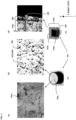
- Fig. 2(a) is an enlarged view of the gasket 104 before the application step.
- the gasket 104 shown in Fig. 2 is the gasket 104 that does not have a tapered shape such as the tapered portion 104b, but includes a planar portion 104e (refer to Fig. 2(c)).
- Fig. 2(b) is an enlarged view of the surface layer 300 formed on the gasket 104 after the application step.
- Fig. 2(c) is a perspective view showing the planar portion 104e of the gasket 104, and Figs. 2(a) and 2(b) show the planar portion 104e before and after the application step. It can be found that as shown in Fig.
- the coating liquid is applied to the surface of the gasket 104 made of rubber, as shown in Fig. 2(b) , the surface layer 300 is formed on the gasket 104, and silicone rubber particles 302 dispersed in the coating liquid.
- silicone rubber particles 302 dispersed in the coating liquid.
- Fig. 2(d) is an enlarged view of a cross section of the base material 104a and the surface layer 300, and is a cross-sectional view of the gasket 104 parallel to the X direction.
- Fig. 2(e) is a cross-sectional view of the gasket 104, and
- Fig. 2(d) shows an enlarged portion on the right side of the cross section, in which the surface layer 300 having a predetermined film thickness is formed on the surface of the gasket 104.
- only one silicone rubber particle 302 is indicated by a reference sign; however, other round structures in the figure are also the silicone rubber particles 302.
- the gasket 104 after baking is subjected to extraction cleaning at a third temperature, for example, at a temperature of room temperature to 200°C, for a third time period, for example, for 5 minutes to 135 minutes.
- the third temperature lower than room temperature requires a cooled liquid (for example, water), which becomes a burden from the viewpoint of the step.
- a cooled liquid for example, water
- the third temperature is higher than 200°C
- deterioration of the base material 104a progresses, which is a risk.
- the third time period is shorter than 5 minutes, cleaning becomes insufficient, and the generation of insoluble fine particles cannot be reduced, which is a risk.
- the third time period is longer than 135 minutes, deterioration of the base material 104a progresses, which is a risk.
- an excessively long time period is not preferable from the viewpoint of the step.
- a coating film having, for example, a predetermined thickness of approximately 5 ⁇ m to 10 ⁇ m is formed on the gasket 104 of the present embodiment by the surface coating layer formation method described above.
- Formulations 1 to 6 correspond to Formulations 1 to 6 of "coating formulations" in the tables of Figs. 4 to 6 to be described later.
- Formulation 1 is a formulation of the coating liquid of the present embodiment, in which a silicon-based material is used as the flexibility-imparting component, and a silicon-based material is also used as the slidability-imparting component. Namely, materials having similar compositions are used for the flexibility-imparting component and the slidability-imparting component.
- Formulation 2 is a formulation for comparison with the present embodiment, in which a silicon-based material is used as the flexibility-imparting component, and no slidability-imparting component is included in the formulation. Namely, Formulation 2 is a formulation under conditions where insoluble fine particles originating from the slidability-imparting component are not generated, which can be regarded as a reference for Formulations 1 to 3.
- Formulation 3 is a formulation for comparison with the present embodiment, in which a silicon-based material is used as the flexibility-imparting component, and a fluorine-based material is used as the slidability-imparting component. Namely, materials having different (distant) compositions are used for the flexibility-imparting component and the slidability-imparting component.
- Formulation 4 is a formulation for comparison with the present embodiment, in which a urethane-based material is used as the flexibility-imparting component, and no slidability-imparting component is included in the formulation. Namely, Formulation 4 is a formulation under conditions where insoluble fine particles originating from the slidability-imparting component are not generated, which can be regarded as a reference for Formulations 4 to 6.
- Formulation 5 is a formulation for comparison with the present embodiment, in which a urethane-based material is used as the flexibility-imparting component, and a silicon-based material is used as the slidability-imparting component. Namely, materials having different compositions are used for the flexibility-imparting component and the slidability-imparting component.
- Formulation 6 is a formulation for comparison with the present embodiment, in which a urethane-based material is used as the flexibility-imparting component, and a fluorine-based material is used as the slidability-imparting component. Namely, materials having different compositions are used for the flexibility-imparting component and the slidability-imparting component.
- a relationship between the application step and the cleaning step in the surface coating layer formation method of the present embodiment was also evaluated. Specifically, an evaluation was performed by comparing the case of performing the cleaning step and the case of not performing the cleaning step using Formulation 1 in which a silicon-based material was used as the flexibility-imparting component and a silicon-based material was used as the slidability-imparting component and Formulation 3 in which a silicon-based material was used as the flexibility-imparting component and a fluorine-based material was used as the slidability-imparting component.
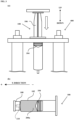
- Fig. 3(a) is a front view showing an experiment setup when a sliding resistance measurement is performed, and also shows an up-down direction.
- a maximum resistance value (N) was measured (hereinafter, referred to as sliding measurement) when each of the syringes 100 including the gaskets 104 with the surface layers of Study Numbers 1 to 17 to be described later was set in a measuring device 400, the surface layers being formed by applying the coating liquids of Formulations 1 to 6 described above, and then causing the coating liquids to undergo appropriate drying and baking steps, and then causing the coating liquids to undergo cleaning, and the plunger 106 was slid downward (indicated by a white arrow in the figure) from above by a distance of 20 mm (hereinafter, also referred to as a sliding distance) at a speed of 100 mm/min (millimeters per minute) (hereinafter, also referred to as a sliding speed).
- slidability refers to the ease of sliding, and the unit of a measurement value is "N (Newton)". The larger the value is, the higher sliding resistance is and the more difficult sliding becomes, and the smaller the value is, the lower sliding resistance is and the easier sliding becomes.
- Fig. 3(b) is a side view showing a setup of the leakage test, and also shows the X direction corresponding to Fig. 1 .
- each of the gaskets 104 with the surface layers of Study Numbers 1 to 17 to be described later was inserted into the outer barrel 102, the surface layers being formed by applying the coating liquids of Formulations 1 to 6, and then causing the coating liquids to undergo appropriate drying and baking steps, and then causing the coating liquids to undergo cleaning, and the outer barrel 102 was filled with a colored surfactant liquid 200a corresponding to the liquid medicine 200 (dummy liquid medicine) from the nozzle 110 at a tip thereof, and the cap 108 was mounted to seal the nozzle 110.
- the gaskets 104 were left in an environment at a temperature of 40°C for 24 hours, and then were transferred to room temperature and were further left for one hour, and in that case, the presence or absence of leakage was checked.
- Each of the gaskets 104 with the surface layers of Study Numbers 1 to 17 to be described later was connected to the plunger 106, the surface layers being formed by applying the coating liquids of Formulations 1 to 6 described above, and then causing the coating liquids to undergo appropriate drying and baking steps, and then causing the coating liquids to undergo cleaning, 2.
- 25 ml of pure water was poured into the outer barrel 102, the gasket 104 and the plunger 106 were inserted into the outer barrel 102 to seal the outer barrel 102, and the nozzle 110 was further covered and sealed with the cap 108. Accordingly, the pure water was sealed in the syringe 100.
- a sterilization step for example, an autoclave sterilization process was performed, and then the syringe 100 was mounted on a shaking apparatus and was shaken, and the number of insoluble fine particles in the pure water was measured.
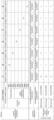
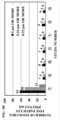
- Fig. 4 is a view showing the results of Evaluation 1
- Fig. 4(a) is a table showing the results of Evaluation 1
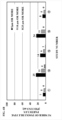
- Fig. 4(b) is a graph showing the number of insoluble fine particles in Evaluation 1.
- Fig. 4(a) shows sample preparation conditions, coating components, and test contents. The test contents show the results of the sliding resistance value (N) described above, the leakage test (no leakage, -), and the insoluble fine particle test (particles/3 ml). In the row for the sample preparation condition, the study number, the formulation of the coating liquid described above (coating formulation), and the cleaning step are shown.
- a material used for the flexibility-imparting component a silicon-based material, a urethane-based material, or the like
- a material used for slidability-imparting component a silicon-based material, a fluorine-based material, or the like
- the cleaning step is extraction cleaning, particularly high-pressure extraction cleaning, and conditions (temperature x time period) when high-pressure extraction cleaning is performed are also shown. "O" attached to a performed step (or condition) represents that the step (or condition) is adopted.
- the horizontal axis indicates the study number
- the vertical axis indicates the number of insoluble fine particles [pieces/3 ml].
- black bars indicate the number of insoluble particles with a particle size of 5 ⁇ m or more
- diagonal pattern bars indicate the number of insoluble fine particles with a particle size of 10 ⁇ m or more
- lattice pattern bars indicate the number of insoluble fine particles with a particle size of 25 ⁇ m or more.
- Fig. 4 also shows the results when no cleaning step is performed on both Formulations 1 and 3 (Study Numbers 7 and 8). Incidentally, Fig. 4 also shows columns for the sliding resistance value and the leakage test; however, Study Numbers 7 and 8 are evaluated based on the results of the insoluble fine particle test.
- the result was that the sliding resistance value was 3.9 N and there was no leakage.
- the number of insoluble fine particles with a particle size of 25 ⁇ m or more was 0 particles/3 ml
- the number of insoluble fine particles with a particle size of 10 ⁇ m or more was 5 particles/3 ml
- the number of insoluble fine particles with a particle size of 5 ⁇ m or more was 7 particles/3 ml.
- insoluble fine particles originating from the slidability-imparting component are not generated, it can be said that 8 insoluble fine particles with a particle size of 5 ⁇ m or more per 3 ml are mixed in the liquid medicine 200. It is considered that the insoluble fine particles are, for example, insoluble fine particles originating from dust suspended in the air, or particles that originally adhere to the container and that cannot be removed in the cleaning step.
- the result was that the sliding resistance value was 5.8 N and there was no leakage.
- the number of insoluble fine particles with a particle size of 25 ⁇ m or more was 0 particles/3 ml
- the number of insoluble fine particles with a particle size of 10 ⁇ m or more was 8 particles/3 ml
- the number of insoluble fine particles with a particle size of 5 ⁇ m or more was 20 particles/3 ml. Namely, it was shown that even if the same silicon-based material was used for the flexibility-imparting component, when a fluorine-based material was used for the slidability-imparting component, a larger number of insoluble fine particles with a particle size of 5 ⁇ m or more were generated than in Formulation 1.
- the sliding resistance value was 21.1 N.
- the number of insoluble fine particles with a particle size of 25 ⁇ m or more was 0 particles/3 ml
- the number of insoluble fine particles with a particle size of 10 ⁇ m or more was 21 particles/3 ml
- the number of insoluble fine particles with a particle size of 5 ⁇ m or more was 27 particles/3 ml.
- the sliding resistance value was also high, and a large number of insoluble fine particles were also observed.
- Formulation 1 using the surface coating layer formation method of the present embodiment was used, but high-pressure extraction cleaning was not performed.
- the number of insoluble fine particles with a particle size of 25 ⁇ m or more was 15 particles/3 ml
- the number of insoluble fine particles with a particle size of 10 ⁇ m or more was 50 particles/3 ml
- the number of insoluble fine particles with a particle size of 5 ⁇ m or more was 63 particles/3 ml.
- Fig. 5 is a view showing the results of Evaluation 2
- Fig. 5(a) is a table showing the results of Evaluation 2
- Fig. 5(b) is a graph showing the number of insoluble fine particles in Evaluation 2.
- Fig. 5(a) shows sample preparation conditions, coating components, and test contents. The test contents show the results of the insoluble fine particle test (pieces/3 ml). In the row for the sample preparation condition, the study number, the coating formulation, and the cleaning step (extraction or high-pressure extraction) are shown.
- a material used for the flexibility-imparting component a silicon-based material, a urethane-based material, or the like
- a material used for slidability-imparting component a silicon-based material, a fluorine-based material, or the like
- conditions temperature x time period
- “O" attached to a performed step (or condition) represents that the step (or condition) is adopted.
- Fig. 5(a) is a table showing the results when the cleaning step is performed on the surface layer 300 of Formulation 1 while changing temperature and time period
- Fig. 5(b) is a graph based on the table of Fig. 5(a) .
- Evaluation 2 is evaluated based on the results of the insoluble fine particle test.
- extraction cleaning and high-pressure extraction cleaning were performed.
- the number of insoluble fine particles with a particle size of 25 ⁇ m or more was 0 particles/3 ml
- the number of insoluble fine particles with a particle size of 10 ⁇ m or more was 5 particles/3 ml
- the number of insoluble fine particles with a particle size of 5 ⁇ m or more was 7 particles/3 ml.
- the number of insoluble fine particles with a particle size of 25 ⁇ m or more was 0 particles/3 ml
- the number of insoluble fine particles with a particle size of 10 ⁇ m or more was 4 particles/3 ml
- the number of insoluble fine particles with a particle size of 5 ⁇ m or more was 8 particles/3 ml.
- the number of insoluble fine particles with a particle size of 25 ⁇ m or more was 0 particles/3 ml
- the number of insoluble fine particles with a particle size of 10 ⁇ m or more was 4 particles/3 ml
- the number of insoluble fine particles with a particle size of 5 ⁇ m or more was 7 particles/3 ml.
- the number of insoluble fine particles with a particle size of 25 ⁇ m or more was 0 particles/3 ml
- the number of insoluble fine particles with a particle size of 10 ⁇ m or more was 2 particles/3 ml
- the number of insoluble fine particles with a particle size of 5 ⁇ m or more was 9 particles/3 ml.
- the number of insoluble fine particles with a particle size of 25 ⁇ m or more was 0 particles/3 ml
- the number of insoluble fine particles with a particle size of 10 ⁇ m or more was 2 particles/3 ml
- the number of insoluble fine particles with a particle size of 5 ⁇ m or more was 6 particles/3 ml.
- Fig. 6 is a view showing the results of Evaluation 3
- Fig. 6(a) is a table showing the results of Evaluation 3
- Fig. 6(b) is a graph showing the number of insoluble fine particles in Evaluation 3.
- Fig. 6 is a table and a graph similar to Fig. 4 .
- the cleaning step of the surface coating layer formation method of the present embodiment the case of using a shaking apparatus, the case of using ultrasonic cleaning, and the case of using a shaker for the surface layer 300 of Formulation 1 were evaluated, and were compared to the case of using high-pressure extraction cleaning of Study Number 1 (Evaluation 1).
- Fig. 6(a) is a table showing the results when the various cleaning steps described above are performed on the surface layer 300 of Formulation 1
- Fig. 6(b) is a graph based on the table of Fig. 6(a) .
- the sliding resistance value was 4.4 N and there was no leakage.
- the number of insoluble fine particles with a particle size of 25 ⁇ m or more was 4 particles/3 ml
- the number of insoluble fine particles with a particle size of 10 ⁇ m or more was 11 particles/3 ml
- the number of insoluble fine particles with a particle size of 5 ⁇ m or more was 25 particles/3 ml.
- a shaking apparatus was used, a large number of insoluble fine particles with a particle size of 25 ⁇ m or more were observed.
- the sliding resistance value was 4.8 N and there was no leakage.
- the number of insoluble fine particles with a particle size of 25 ⁇ m or more was 1 particle/3 ml
- the number of insoluble fine particles with a particle size of 10 ⁇ m or more was 6 particles/3 ml
- the number of insoluble fine particles with a particle size of 5 ⁇ m or more was 14 particles/3 ml.
- insoluble fine particles with a particle size of 25 ⁇ m or more were observed.
- the sliding resistance value was 4.2 N and there was no leakage.
- the number of insoluble fine particles with a particle size of 25 ⁇ m or more was 0 particle/3 ml
- the number of insoluble fine particles with a particle size of 10 ⁇ m or more was 11 particles/3 ml
- the number of insoluble fine particles with a particle size of 5 ⁇ m or more was 24 particles/3 ml.
- a shaker was used, a large number of insoluble fine particles with a particle size of 5 ⁇ m or more were observed.
- the result was that the sliding resistance value was 3.7 N and there was no leakage.
- the number of insoluble fine particles with a particle size of 25 ⁇ m or more was 0 particles/3 ml
- the number of insoluble fine particles with a particle size of 10 ⁇ m or more was 5 particles/3 ml
- the number of insoluble fine particles with a particle size of 5 ⁇ m or more was 8 particles/3 ml. Even if ultrasonic cleaning was used after high-pressure extraction cleaning, no large difference was observed compared to when only high-pressure extraction cleaning was performed.
- Study Number 1 of the present embodiment to Study Numbers 2, 3, and 5 to 17 that are comparative examples, which have been described using Figs. 4 to 6 , will be summarized below.
- the present embodiment it is possible to provide the surface coating layer formation method and the gasket manufacturing method capable of reducing the falling off of insoluble fine particles into the liquid medicine while preventing leakage of the liquid medicine and maintaining stable slidability.
- the present invention includes the following concepts.
- a surface coating layer formation method of the present invention is a surface coating layer formation method by which a surface coating layer for improving slidability is formed on a surface of a sliding member using rubber as a base material, a material of the surface coating layer having a composition in which silicon-based rubber particles are contained in a silicon-based solution, the method including: an application step of applying the material to a surface of the base material so as to have a predetermined coating thickness; a drying step of drying the sliding member after the application at a first temperature for a first time period; a baking step of baking the sliding member after the drying at a second temperature for a second time period; and a cleaning step of extraction-cleaning the sliding member after the baking at a third temperature for a third time period.
- a particle size of the silicon-based rubber particles may be 1 ⁇ m or more and 50 ⁇ m or less in average particle size.
- the predetermined coating thickness may be 1 ⁇ m or more and 50 ⁇ m or less.
- the third temperature may be room temperature or higher and 200°C or lower, and the third time period may be 5 minutes or more and 135 minutes or less.
- a surface coating layer formation method of the present invention is a surface coating layer formation method by which a surface coating layer for improving slidability is formed on a surface of a gasket that is disposed at a tip portion of a plunger used in a syringe and that slides against an inner barrel wall of the syringe, a material of the surface coating layer having a composition in which silicon-based rubber particles are contained in a silicon-based solution, the method including: an application step of applying the material to the surface of the gasket so as to have a predetermined coating thickness; a drying step of drying the gasket after the application at a first temperature for a first time period; a baking step of baking the gasket after the drying at a second temperature for a second time period; and a cleaning step of extraction-cleaning the gasket after the baking at a third temperature for a third time period.
- a gasket manufacturing method of the present invention is a gasket manufacturing method by which a gasket that is disposed at a tip portion of a plunger used in a syringe and that slides against an inner barrel wall of the syringe, the gasket including a surface coating layer for improving slidability on a surface of a rubber base material, a material of the surface coating layer having a composition in which silicon-based rubber particles are contained in a silicon-based solution, the method including: an application step of applying the material to a surface of the base material so as to have a predetermined coating thickness; a drying step of drying the gasket after the application at a first temperature for a first time period; a baking step of baking the gasket after the drying at a second temperature for a second time period; and a cleaning step of extraction-cleaning the gasket after the baking at a third temperature for a third time period.
Landscapes
- Engineering & Computer Science (AREA)
- Chemical & Material Sciences (AREA)
- Health & Medical Sciences (AREA)
- Life Sciences & Earth Sciences (AREA)
- Materials Engineering (AREA)
- Wood Science & Technology (AREA)
- Organic Chemistry (AREA)
- Heart & Thoracic Surgery (AREA)
- Veterinary Medicine (AREA)
- Vascular Medicine (AREA)
- Anesthesiology (AREA)
- Biomedical Technology (AREA)
- Hematology (AREA)
- Animal Behavior & Ethology (AREA)
- General Health & Medical Sciences (AREA)
- Public Health (AREA)
- General Engineering & Computer Science (AREA)
- Nanotechnology (AREA)
- Combustion & Propulsion (AREA)
- Chemical Kinetics & Catalysis (AREA)
- Mechanical Engineering (AREA)
- Infusion, Injection, And Reservoir Apparatuses (AREA)
- Application Of Or Painting With Fluid Materials (AREA)
- Paints Or Removers (AREA)
Applications Claiming Priority (2)
| Application Number | Priority Date | Filing Date | Title |
|---|---|---|---|
| JP2022064355A JP2023154791A (ja) | 2022-04-08 | 2022-04-08 | 表面被覆層形成方法及びガスケットの製造方法 |
| PCT/JP2023/012541 WO2023195389A1 (fr) | 2022-04-08 | 2023-03-28 | Procédé de formation de couche de revêtement de surface et procédé de production de joint |
Publications (2)
| Publication Number | Publication Date |
|---|---|
| EP4506067A1 true EP4506067A1 (fr) | 2025-02-12 |
| EP4506067A4 EP4506067A4 (fr) | 2026-05-13 |
Family
ID=88242894
Family Applications (1)
| Application Number | Title | Priority Date | Filing Date |
|---|---|---|---|
| EP23784679.5A Pending EP4506067A4 (fr) | 2022-04-08 | 2023-03-28 | Procédé de formation de couche de revêtement de surface et procédé de production de joint |
Country Status (4)
| Country | Link |
|---|---|
| US (1) | US12582778B2 (fr) |
| EP (1) | EP4506067A4 (fr) |
| JP (1) | JP2023154791A (fr) |
| WO (1) | WO2023195389A1 (fr) |
Family Cites Families (12)
| Publication number | Priority date | Publication date | Assignee | Title |
|---|---|---|---|---|
| JP2746882B2 (ja) * | 1987-09-02 | 1998-05-06 | 株式会社大協精工 | 変性ポリシロキサン被覆医薬品用ゴム栓及びその製造法 |
| US5114794A (en) | 1987-06-23 | 1992-05-19 | Daikyo Gomu Seiko Ltd. | Modified polysiloxane-coated sanitary rubber article and a process for the production of the same |
| JPH06301Y2 (ja) * | 1987-10-15 | 1994-01-05 | 株式会社神戸製鋼所 | 車両系建設機械の油圧回路 |
| JP2586583B2 (ja) | 1988-06-28 | 1997-03-05 | 日本電気株式会社 | 有機薄膜el素子用有機蛍光体 |
| JPH07126417A (ja) * | 1993-10-13 | 1995-05-16 | Toyoda Gosei Co Ltd | ゴム物品の表面処理方法ならびに同方法により処理されたゴム物品 |
| US6296907B1 (en) * | 1996-05-31 | 2001-10-02 | Wacker Silicones Corporation | Coating for silicone gaskets to reduce coefficient of friction |
| JP4708013B2 (ja) | 2004-12-15 | 2011-06-22 | テルモ株式会社 | シリンジ |
| JP2006167111A (ja) | 2004-12-15 | 2006-06-29 | Heiwa Corp | 遊技機 |
| JP2008000287A (ja) | 2006-06-21 | 2008-01-10 | Terumo Corp | 医療用具コーティング用摺動性組成物および摺動性被膜保有医療用具 |
| US8802603B2 (en) * | 2010-06-17 | 2014-08-12 | Becton, Dickinson And Company | Medical components having coated surfaces exhibiting low friction and low reactivity |
| EP4039465B1 (fr) * | 2019-09-30 | 2025-07-23 | Asahi Rubber Inc. | Matériau de caoutchouc coulissant possédant une couche à interface modifiée à modification amino, et procédé de fabrication de celui-ci |
| US20230060079A1 (en) * | 2019-12-20 | 2023-02-23 | Hospira, Inc. | Surface modifying coating for medical devices |
-
2022
- 2022-04-08 JP JP2022064355A patent/JP2023154791A/ja active Pending
-
2023
- 2023-03-28 US US18/854,058 patent/US12582778B2/en active Active
- 2023-03-28 EP EP23784679.5A patent/EP4506067A4/fr active Pending
- 2023-03-28 WO PCT/JP2023/012541 patent/WO2023195389A1/fr not_active Ceased
Also Published As
| Publication number | Publication date |
|---|---|
| US20250065052A1 (en) | 2025-02-27 |
| WO2023195389A1 (fr) | 2023-10-12 |
| JP2023154791A (ja) | 2023-10-20 |
| US12582778B2 (en) | 2026-03-24 |
| EP4506067A4 (fr) | 2026-05-13 |
Similar Documents
| Publication | Publication Date | Title |
|---|---|---|
| CN101909675B (zh) | 注射器用垫圈及具有该垫圈的注射器 | |
| EP2910265B1 (fr) | Joint d'étanchéité de seringue et seringue préremplie | |
| EP2796520B1 (fr) | Récipient ayant de faibles émissions de particules et une surface lisse et sèche à friction contrôlée et son procédé de fabrication | |
| JP6207401B2 (ja) | プレフィルドシリンジ用シリンジ | |
| US10684189B2 (en) | Air tight packaging container for easy leakage test and leakage test method and apparatus using same | |
| JP7018619B2 (ja) | アミノ変性界面改質層を有する摺動性ゴム材、及びそれを製造する方法 | |
| EP3437680B1 (fr) | Seringue à haute capacité de glissement | |
| WO2016051989A1 (fr) | Ensemble de seringue, seringue préremplie, capuchon d'étanchéité pour gaine avec aiguille de ponction, et emballage d'ensemble de seringue | |
| EP3708205B1 (fr) | Contenant pharmaceutique et composition liquide | |
| US20170082129A1 (en) | Liquid-resistant sealing fastener assembly | |
| EP1792657B1 (fr) | Récipient avec couvercle | |
| US12582778B2 (en) | Surface coating layer formation method and gasket manufacturing method | |
| Allen et al. | Investigation into the effects of environmental stresses on RTV-1 silicone-based caulk materials | |
| JP4708013B2 (ja) | シリンジ | |
| WO2011072110A1 (fr) | Article moulé pourvu d'une couche de décollage appliquée par le moule | |
| CN1273358C (zh) | 用于包装至少一种化妆品的装置和用于临时混合至少两种产品的装置 | |
| WO2015151671A1 (fr) | Joint de seringue et seringue équipée dudit joint | |
| JP5586155B2 (ja) | 歯科材料用シリンジ | |
| CN1933748A (zh) | 带涂敷体的容器 | |
| JP2000131326A (ja) | 試料容器用キャップ | |
| US10946837B2 (en) | Wiper blade rubber | |
| JP2891838B2 (ja) | 医薬品用,医療用ゴム栓およびその製造方法 | |
| US20080251491A1 (en) | Closure with Oxygen Absorption | |
| LU101852B1 (en) | Device for measuring negative pressure | |
| JP2018135469A (ja) | 撥水処理剤 |
Legal Events
| Date | Code | Title | Description |
|---|---|---|---|
| STAA | Information on the status of an ep patent application or granted ep patent |
Free format text: STATUS: THE INTERNATIONAL PUBLICATION HAS BEEN MADE |
|
| PUAI | Public reference made under article 153(3) epc to a published international application that has entered the european phase |
Free format text: ORIGINAL CODE: 0009012 |
|
| STAA | Information on the status of an ep patent application or granted ep patent |
Free format text: STATUS: REQUEST FOR EXAMINATION WAS MADE |
|
| 17P | Request for examination filed |
Effective date: 20241101 |
|
| AK | Designated contracting states |
Kind code of ref document: A1 Designated state(s): AL AT BE BG CH CY CZ DE DK EE ES FI FR GB GR HR HU IE IS IT LI LT LU LV MC ME MK MT NL NO PL PT RO RS SE SI SK SM TR |
|
| DAV | Request for validation of the european patent (deleted) | ||
| DAX | Request for extension of the european patent (deleted) | ||
| A4 | Supplementary search report drawn up and despatched |
Effective date: 20260415 |
|
| RIC1 | Information provided on ipc code assigned before grant |
Ipc: B05D 3/00 20060101AFI20260409BHEP Ipc: A61M 5/315 20060101ALI20260409BHEP Ipc: B05D 3/02 20060101ALI20260409BHEP Ipc: B05D 5/00 20060101ALI20260409BHEP Ipc: B05D 7/02 20060101ALI20260409BHEP Ipc: C09D 7/65 20180101ALI20260409BHEP Ipc: C09D 183/04 20060101ALI20260409BHEP Ipc: F16J 1/01 20060101ALI20260409BHEP Ipc: C09D 7/40 20180101ALI20260409BHEP Ipc: B05D 5/08 20060101ALI20260409BHEP Ipc: C09D 5/00 20060101ALI20260409BHEP |