EP4506076A1 - Prévention de la baisse de la vitesse de rotation lors du l'enfilage - Google Patents
Prévention de la baisse de la vitesse de rotation lors du l'enfilage Download PDFInfo
- Publication number
- EP4506076A1 EP4506076A1 EP23190660.3A EP23190660A EP4506076A1 EP 4506076 A1 EP4506076 A1 EP 4506076A1 EP 23190660 A EP23190660 A EP 23190660A EP 4506076 A1 EP4506076 A1 EP 4506076A1
- Authority
- EP
- European Patent Office
- Prior art keywords
- rolling
- time
- control device
- drive
- torque
- Prior art date
- Legal status (The legal status is an assumption and is not a legal conclusion. Google has not performed a legal analysis and makes no representation as to the accuracy of the status listed.)
- Withdrawn
Links
Images




Classifications
-
- B—PERFORMING OPERATIONS; TRANSPORTING
- B21—MECHANICAL METAL-WORKING WITHOUT ESSENTIALLY REMOVING MATERIAL; PUNCHING METAL
- B21B—ROLLING OF METAL
- B21B37/00—Control devices or methods specially adapted for metal-rolling mills or the work produced thereby
- B21B37/46—Roll speed or drive motor control
-
- B—PERFORMING OPERATIONS; TRANSPORTING
- B21—MECHANICAL METAL-WORKING WITHOUT ESSENTIALLY REMOVING MATERIAL; PUNCHING METAL
- B21B—ROLLING OF METAL
- B21B2273/00—Path parameters
- B21B2273/06—Threading
- B21B2273/08—Threading-in or before threading-in
-
- B—PERFORMING OPERATIONS; TRANSPORTING
- B21—MECHANICAL METAL-WORKING WITHOUT ESSENTIALLY REMOVING MATERIAL; PUNCHING METAL
- B21B—ROLLING OF METAL
- B21B2275/00—Mill drive parameters
- B21B2275/02—Speed
- B21B2275/04—Roll speed
-
- B—PERFORMING OPERATIONS; TRANSPORTING
- B21—MECHANICAL METAL-WORKING WITHOUT ESSENTIALLY REMOVING MATERIAL; PUNCHING METAL
- B21B—ROLLING OF METAL
- B21B2275/00—Mill drive parameters
- B21B2275/10—Motor power; motor current
Definitions
- the present invention is further based on a control program which has machine code which can be processed by a control device for a rolling stand for rolling a rolled metal stock having a rolling stock head, wherein the processing of the machine code by the control device causes the control device to carry out such an operating method.
- the present invention is further based on a control device for a rolling stand for rolling a metal rolling stock having a rolling stock head, wherein the control device is programmed with such a control program so that it carries out such an operating method during operation.
- the quality of the end product depends on many factors.
- the rolled product can in particular be a flat rolled product, for example a strip or a heavy plate.
- the factors that influence the quality of the end product include the material temperature, lubrication during rolling, the correct pressure conditions of the rolls and the speed or peripheral speed of the work rolls. Whether we are talking about the speed or the peripheral speed is equivalent, since the peripheral speed and the speed can be converted into one another using the diameter of the work rolls.
- the desired speed is maintained as precisely as possible with regard to the speed of the work rolls. Any deviation leads to negative effects such as a reduction in product quality, material jams (for example, the formation of a belt loop), inaccuracies in dependent process variables, difficulties in material guidance and others.
- the dimensions of the end product can also vary as a result.
- the required accuracy can be ensured by using simple and robust controls.
- the transition from one stable operating range to another stable operating range is considerably more difficult. This applies in particular to the point at which the rolling stock head enters the rolling stand. At this point, the load on the rolling stand changes. In particular, the required rolling force and the required rolling torque increase considerably. The changes occur almost instantly at the point at which the rolling stock head enters the rolling stand.
- the object of the present invention is to create possibilities by means of which the collapse of the speed of the driven rollers can be completely or at least almost completely avoided.
- an operating method of the type mentioned at the outset is designed in that the control device determines the torque curve starting from an initial state of the drive, the drive train and the driven rollers of the rolling stand given at the initial time in such a way that the driven rollers of the rolling stand are subjected to the rolling torque by the drive train at the time of piercing and rotate at a peripheral speed coordinated with the rolling speed.
- the driven rolls of the rolling stand are driven. Furthermore, since the torque delivered by the drive cannot be increased to the rolling torque as quickly as desired, the driven rolls of the rolling stand are accelerated by increasing the torque to the rolling torque required to roll the rolling stock before the tapping point. The extent of the acceleration is determined by the moving masses or the associated moments of inertia and the rolling torque. For this reason, the peripheral speed of the driven rolls shortly before the tapping point must also be lower than the peripheral speed corresponding to the rolling speed.
- the peripheral speed reaches the desired peripheral speed at the time of the tapping, which corresponds to the rolling speed.
- the deviations of the peripheral speed from the rolling speed before the time of the tapping are not critical, since no material is rolled in the roll gap of the rolling stand during this time.
- the rolling speed and the peripheral speed of the driven rolls are not necessarily one and the same.
- the rolling stock enters the rolling stand at an entry speed that is lower than the peripheral speed of the driven rolls.
- the rolling stock leaves the rolling stand at an exit speed that is higher than the peripheral speed of the driven rolls.
- the corresponding speed ratios are known in specialist circles as lag and lead.
- the term "rolling speed" can mean the entry speed, the exit speed or a value between the entry speed and the exit speed. Regardless of the specific definition of the rolling speed, however, there is a fixed relationship between the rolling speed and the peripheral speed.
- the control device can know the point in time of the piercing, for example, based on a standard path tracking in conjunction with a (constant or time-variable) rolling stock speed.
- Path tracking is generally known to experts and therefore does not need to be explained in more detail.
- the starting point is usually determined indirectly by the length of the period being fixed.
- the driven rolls of the rolling stand are usually the working rolls of the rolling stand. In exceptional cases, however, backup rolls or intermediate rolls of the rolling stand can also be driven.
- control device determines the torque curve in such a way that at the time of tapping, the drive, the drive train and the driven rollers of the rolling stand rotate at corresponding speeds and changes in the speeds have the value zero. This ensures that a transient state, which must (still) exist before the time of tapping, has just subsided at the time of tapping.
- control device determines the torque curve using a model that models the drive, the drive train and the rolls of the rolling stand driven by the drive based on mathematical and physical equations. This approach allows the control device to flexibly handle almost any boundary conditions.
- the drive, the drive train and the driven rollers of the rolling stand are modelled as a rigid system using the model.
- the speed of the drive is in a fixed ratio to the speed of the driven rollers, which has the same value at all times.
- torsions often occur, for example between the drive and the drive train and between the drive train and the driven rollers. It is therefore preferable for the model to model the drive, the drive train and the driven rollers of the rolling stand as a multi-mass vibration system with a number of damped-elastically connected elements. This means that such torsions can also be taken into account.
- the number of damped-elastically connected elements can be determined as required. As a rule, it is at least three, namely the drive, the drive train (in this case considered as a unit) and the driven rollers. If necessary, the drive train can also be divided into several sections. In this case, the number of damped-elastically connected elements increases accordingly.
- One way to determine the torque curve is for the control device to set up an optimization problem in which the respective torque of the drive is included as an input variable for a number of discrete points in time within the period.
- the control device determines the torque curve by solving the optimization problem.
- control device determines the torque curve using tables stored in the control device, to which the tapping time, the rolling speed, the rolling torque and the initial state of the drive, the drive train and the driven rollers of the rolling stand are fed as input variables. It is also alternatively possible for the torque curve to be given to the control device by a parameterizable function of time stored in the control device and for the control device to determine the parameters of the function based on the tapping time, the rolling speed, the rolling torque and the initial state of the drive, the drive train and the driven rollers of the rolling stand.
- the tables can be determined, for example, by determining the corresponding entries in the tables in advance and offline using a model for a large number of possible value combinations and the results of the model-based calculations stored in the control device. An analogous procedure is possible for determining the dependencies of the parameters on the possible value combinations.
- the drive, the drive train and the driven rollers of the rolling stand rotate at corresponding speeds and changes in the speeds have a value of zero.
- the drive, the drive train and the driven rollers of the rolling stand are in a stable state at the initial time. This procedure makes it easier to determine the torque curve.
- the procedure according to the invention implies that the driven rollers of the rolling stand are accelerated at least shortly before the time of penetration.
- the peripheral speed of the driven rollers must therefore be lower than the peripheral speed of the driven rollers that is coordinated with the rolling speed. It is possible that this situation does not yet exist at the start of the process.
- the driven rollers of the rolling stand must first be braked and then accelerated during the period. However, this situation is preferably already present in the initial state. This procedure can reduce both the energy requirement and the wear. For example, after rolling a rolling stock in the rolling stand, i.e. after the rolling stock foot of this rolling stock has left the rolling stand, the driven rollers can be allowed to slowly run down until they rotate at the desired (low) peripheral speed that is desired for the next rolling stock at the start of the process.
- control device determines the torque curve in such a way that the torque generated by the drive and/or an application torque is greater than a respective predetermined minimum value during the entire period.
- the application torque is, as already mentioned, the torque with which the driven rolls of the rolling stand are driven.
- control device preferably determines the torque curve such that a rotational acceleration with which a rotational speed of the drive changes and/or a rotational acceleration with which a rotational speed of the driven rollers changes is greater than a respective predetermined minimum value during the entire period.
- the respective minimum value may in particular be zero.
- the load on the drive, the drive train and the driven rolls of the rolling mill can be equalized.
- This procedure is particularly advantageous in conjunction with the design in which, in the initial state, the peripheral speed of the driven rollers is lower than the peripheral speed of the driven rollers matched to the rolling speed.
- control device determines the torque curve in such a way that energy consumption of the drive is minimal during the period.
- the time period is preferably between 50 ms and 200 ms, in particular between 75 ms and 150 ms.
- the time period is therefore sufficiently long to be able to build up the load torque required at the time of tapping in the manner according to the invention.
- control program with the features of claim 13.
- processing of the control program causes the control device to carry out an operating method according to the invention.
- control device with the features of claim 14.
- the control device is programmed with a control program according to the invention, so that the control device executes an operating method according to the invention during operation.
- the control device is designed as a control device according to the invention.
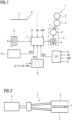
- a rolling device has a rolling stand 1.
- a rolling stock 2 is to be rolled in the rolling stand 1.
- the rolling stand 1 is often part of a multi-stand rolling mill. However, this is not absolutely necessary. Regardless of the number of additional rolling stands, only the procedure for the rolling stock 2 in FIG 1
- the rolling stand 1 shown in Figure 1 is explained in more detail. This is also possible and sufficient in the present case, since the mode of operation of the rolling stand 1 of FIG 1 is independent of the operation of other rolling stands, for example one of the FIG 1 shown rolling stand 1 or a rolling stand arranged upstream of the rolling stand FIG 1 rolling stand 1 downstream of the rolling stand 1 shown. If several rolling stands 1 are present, the inventive mode of operation of the rolling stand 1 can also be implemented in an analogous manner in the other rolling stands.
- the rolling stand 1 of FIG 1 has reels 3, which - see also FIG 2 - are driven by means of a drive 4 via a drive train 5.
- the driven rollers 3 are often the work rollers of the rolling stand 1. If the rolling stand 1 has other rollers in addition to the work rollers, in individual cases the driven rollers 3 can also be rollers other than the work rollers. As a rule, however, the driven rollers 3 are also the work rollers of the rolling stand 1 in this case.
- the entirety of the drive 4, drive train 5 and driven rollers 3 is referred to below as the drive system.
- an upper driven roller 3 and a lower driven roller 3 each have their own drive 4 and their own drive train 5.
- the drive train 5 is split so that the drive 4 drives both driven rollers 3. Whether one or the other approach is taken is of secondary importance within the scope of the present invention.
- the rolled stock 2 consists of metal.
- the rolled stock 2 usually consists of steel. However, it can also be another metal, for example aluminum, copper or brass.
- the rolled stock 2 is usually a flat rolled stock, i.e. a rolled stock 2 that is rolled into a strip or a heavy plate. In individual cases, however, it can also be a rod-shaped rolled stock, in particular bar steel. Regardless of the shape and material, the rolled stock 2 always has a rolled stock head 6.
- the rolled stock head 6 is the area of the rolled stock 2 that first reaches the rolling stand 1 and runs into the rolling stand 1.
- FIG 1 shows a situation at a time t1 at which the rolling stock head 6 has not yet reached the rolling stand 1.
- the rolling stock head 6 is at this time at a distance in front of the rolling stand 1.
- dashed lines there is still a distance in front of the rolling stand 1.
- the rolling stock head 6 reaches the corresponding location at a time t2.
- the rolling stock head 6 also reaches the roll gap of the rolling stand 1 at a time t3, i.e. it runs into the rolling stand 1 at this time.
- the time t1 is referred to below as the information time.
- the time t2 is referred to below as the start time.
- the time t3 is referred to below, as is generally customary, as the tapping time.
- the start time t2 is usually between 50 ms and 200 ms before the tapping time t3, in particular between 75 ms and 150 ms before the tapping time t3, for example approx. 100 ms before the tapping time t3.
- the rolling stand 1 is controlled by a control device 7.
- the control device 7 is programmed with a control program 8.
- the control program 8 has machine code 9 that can be processed by the control device 7.
- the programming of the control device 7 with the control program 8 or the processing of the machine code 9 by the control device 7 causes the control device 7 to carry out an operating method that is explained in more detail below.
- the present invention relates to a procedure that is taken before the rolling stock head 6 enters the rolling stand 1.
- the control device 7 To implement the operating method according to the invention, it is necessary for the control device 7 to know the starting time t2 and the piercing time t3 in good time so that the calculations required for the operating method according to the invention are completed by the starting time t2 at the latest.
- the information time t1 is before the starting time t2.
- the extent to which the information time t1 is before the starting time t2 can be determined as required. It is crucial that calculations that are carried out by the control device 7 and are required for the correct control of the rolling stand 1 from the starting time t2 are completed before the starting time t2.
- a suitable determination and adherence to the information time t1 is easily possible, since the location of the rolling stock head 6 can be detected in good time before the time t1 and this can be made known to the control device 7 and then a usual tracking of the rolling stock head 6 can take place based on the detected location and the constant or time-dependent rolling stock speed v of the rolling stock 2.
- the current and future rolling stock speed v can be easily known to the control device 7. All of this is generally known to experts and is therefore not explained in more detail below.
- the rolling stock speed v is not referred to here as the rolling speed. The reason for this is that the rolling stock speed v here relates to the period of time at which the rolling stock head 6 has not yet reached the rolling stand 1, i.e. rolling is not yet taking place in the rolling stand 1.
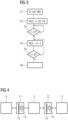
- a step S1 the control device 7 is informed of the tapping time t3, a rolling speed vW and a rolling torque MW.
- the rolling speed vW is the speed at which the rolling stock 2 is to be rolled in the rolling stand 1 at least at the tapping time t3.
- the rolling torque MW is the associated torque with which the driven rollers 3 are to and must be driven by the drive 4 via the drive train 5. It is possible that the values t3, vW, MW mentioned are specified to the control device 7 from outside. Alternatively, it is possible that they are determined by the control device 7 itself. The determination of the tapping time t3, the rolling speed vW and the rolling torque MW is not explained in more detail here. They are generally known to experts. Step S1 is carried out by the control device 7 at the information time t1.
- step S2 the control device 7 determines a torque curve M for the drive 4 for a period of time that extends from the starting time t2 to the tapping time t3.
- the torque curve M is a function of time t. Possible embodiments of step S2 will be explained in more detail later. In any case, however, the control device 7 starts from an initial state x2 of the drive system to determine the torque curve M.
- the initial state x2 is the state x of the drive system that exists at the starting time t2.
- the determination of step S2 also takes place in such a way that the driven rollers 3 are subjected to the rolling torque MW by the drive train 5 at the tapping time t3 and rotate at a peripheral speed vU that is coordinated with the rolling speed vW.
- the peripheral speed vU is linked to the rolling speed vW via the lead or the lag, depending on whether the inlet side or the outlet side rolling speed is meant.
- the torque curve M is determined in such a way that at the tapping time t3, the drive 4, the drive train 5 and the driven rollers 3 of the rolling stand 1 rotate at corresponding speeds and changes in the speeds have the value zero.
- the step S2 is carried out by the control device 7 before the tapping time t3, more precisely even before the starting time t2.
- the initial state x2 can be specified to the control device 7.
- the control device 7 it is possible for the control device 7 to determine the initial state x2 and control the drive 4 in such a way that the initial state x2 is present at the initial time t2. It is also possible for the initial time t2 to be specified to the control device 7. However, the control device 7 usually knows how long the period between the initial time t2 and the tapping time t3 should be, so that the control device 7 can determine the initial time t2 itself.
- step S3 the control device 7 waits for the starting time t2.
- the step S3 is repeatedly carried out until the starting time t2 is reached. From the starting time t2, the control device 7 repeatedly carries out steps S4 and S5.
- step S4 the control device 7 controls the drive 4 according to the determined torque curve M for the respective time t.
- the control device 7 can FIG 1 control the drive 4 by outputting corresponding control signals to a converter 4', which supplies an electric motor 4" with electrical energy.
- the representation of the converter 4' in FIG 1 as a thyristor control is purely an example. It could also be a transistor control.
- step S5 the control device 7 checks whether the tapping time t3 has been reached. If the tapping time t3 has not yet been reached, the control device 7 returns to step S4. Steps S4 and S5 are therefore repeatedly carried out by the control device 7 until the tapping time t3 is reached. When executing step S4, the control device 7 naturally takes the progress in time t into account.
- step S6 the "normal" rolling of the rolling stock 2 takes place.
- the step S6 can be implemented in the same way as in the prior art.
- the drive 4, the drive train 5 and the driven rollers 3 can be considered in the simplest case as being completely rigidly connected to one another.
- the speed of the drive 4 at any time t corresponds to the speed of the driven rollers 3.
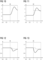
- the control device 7 it is possible for the control device 7 to determine the torque curve M using a model 10 (see FIG 4 ), which models the drive system based on mathematical-physical equations.
- the drive 4 is connected to the drive train 5 via a coupling 11 and that the drive train 5 is also connected to the driven rollers 3 via a coupling 12.
- the two couplings 11, 12 are, as in FIG 4 indicated by a respective spring component 13 and a respective damper component 14, each damped-elastic coupling.
- FIG 4 thus shows a design in which the drive system is modelled as a three-mass oscillator.
- one of the two couplings 11, 12 can be disregarded.
- the drive system can be modelled as a two-mass oscillator. If both couplings 11, 12 are disregarded, the drive system is modelled as a completely rigid System is modelled. In other cases, a division into more than three damped-elastically coupled elements is made. In this case, in addition to the two couplings 11, 12, further damped-elastic couplings are present.
- the target speed w* corresponds to the peripheral speed vU which the driven rollers 3 must have for the desired rolling speed vW.
- a further condition is that at the piercing time t3 the loading torque ML is equal to the desired rolling torque MW.
- equation (11) only applies if the speed of the driven rollers 3 is to be kept constant after the tapping time t3. If the driven rollers 3 are to be accelerated or decelerated after the tapping time t3, an additional torque can be taken into account on the right-hand side of equation (11) in addition to the rolling torque MW.
- the motor torque M applied by the drive 4 cannot be changed as quickly as desired. Furthermore, as described by equations (1) to (3), there are generally certain elasticities, damping and losses.
- the torque curve M of the drive 4 must therefore be determined in a suitable manner so that the conditions according to equations (10) and (11) are met.
- transient conditions when accelerating the driven rollers 3 to the target speed w* should already be adjusted.
- the required state x3 of the drive system at the tapping time t3 - hereinafter referred to as the target state x3 - is clearly determined. Since the rolling stock head 6 is located immediately before the tapping time t3 but still in front of the rolling stand 1, but not in the rolling stand 1, an acceleration still takes effect in the drive system immediately before the tapping time t3. It is therefore necessary, starting from the initial state x2 of the drive system, to determine the associated torque curve M, by means of which the drive system is transferred to the target state x3.
- the initial state x2 is known to the control device 7.
- the initial state x2 is a stable state, i.e. a state in which the drive 4, the drive train 5 and the driven rollers 3 of the rolling stand 1 rotate at corresponding speeds ⁇ i and changes in the speeds ⁇ i have the value zero.
- the peripheral speed vU of the driven rollers 3 can in principle have any value in the initial state x2.
- the peripheral speed vU of the driven rollers 3 can - purely theoretically - be greater than the value coordinated with the rolling speed vW, have the value 0 or even be negative.
- peripheral speed vU of the driven rollers 3 is positive, but smaller than the peripheral speed vU of the driven rollers 3 coordinated with the rolling speed vW.
- the reasons for this will become clear from later explanations.
- the states of the drive system before the initial time t2 are not relevant in this case.
- step S2 of FIG 3 various approaches are possible. In some simple cases it may be possible to determine the torque curve M analytically. This can be possible in particular if the drive system can be considered as a rigid system. It may also be possible to determine the torque curve M using a so-called flatness-based trajectory calculation. Such calculations are known to experts as such. In any case, however, it is possible to determine the torque curve M using the representation in FIG 7 To determine the moment curve M, an optimization problem must be set: min M ⁇ t 2 t 3 x t ⁇ x ′ T Q x t ⁇ x ′ + M t ⁇ M ′ R M t ⁇ M ′ dt .
- the torque curve M can be influenced by the state x'.
- Q is a weighting matrix with which the deviation of the respective state x(t) from the desired state x' is weighted.
- the weighting matrix Q is positive (semi-) definite.
- M' is an engine torque that should be aimed for if possible.
- the desired engine torque M' can be constant or time-dependent.
- the torque curve M can also be influenced by the desired engine torque M'.
- R is a positive definite weighting matrix, in this case a positive weighting factor, with which the deviation of the engine torque M(t) from the desired engine torque M' is weighted.
- the engine torque M3 is uniquely determined by the system of equations according to equations (10) to (15).
- the engine torque M is within the permissible limits at any time t between the initial time t2 and the starting time t3, i.e. it does not fall below a minimum value Mmin and does not exceed a maximum value Mmax: M min ⁇ M t ⁇ M max .
- Examples of possible inequality constraints h can be, for example, specifications that certain changes in the angular velocities ⁇ i or certain rotations ⁇ i are not exceeded. It can also be specified that the respective moment acting between successive elements of the modeled drive system does not exceed certain limits.
- Equation (16) The optimization problem according to equation (16) can be solved analytically, if this is possible. It is always possible to solve the optimization problem numerically. Numerical solution implies that equation (16) is not solved in a time continuum, but that the period extending from the starting time t2 to the tapping time t3 is divided into small time steps (discretized). As a result, an optimization problem is set in which the respective torque M of the drive 4 is included as input variables for a plurality of discrete times t within the specified period. The solution found corresponds to the desired torque curve M. The torque curve M is thus determined by minimizing or solving the optimization problem.
- control device 7 determines the torque curve M using tables 15, which are stored in the control device 7.
- the input variables for the tables 15 are the piercing time t3, the rolling speed vW, the rolling torque MW and the Initial state x2 of the drive system.
- the distance between the initial time t2 and the piercing time t3 can be known in advance to the control device 7.
- a function f a of the time t can be stored in the control device.
- the function f a can be parameterized with parameters a.
- the torque curve M is given to the control device 7 by the function f a .
- the control device 7 determines the parameters a of the function f a based on the piercing time t3, the rolling speed vW, the rolling torque MW and the initial state x2 of the drive system.
- the control device 7 determines the torque curve M in such a way that the torque M generated by the drive 4 and/or the loading torque ML with which the driven rollers 3 are loaded is greater than a respective predetermined minimum value during the entire period extending from the starting time t2 to the tapping time t3. This does not mean that one looks at the result "torque curve M" or "course of the loading torque ML", then determines the respective minimum value and then comes to the conclusion that the entire corresponding course is above the respective minimum value. This would correspond to a procedure according to the motto "you shoot an arrow; where it hits, that is the target”.
- the respective minimum value is specified before the determination of the torque curve M, i.e. before the execution of step S2 of FIG 3 .
- the determination of the torque curve M is then carried out in such a way that the respective minimum value is maintained.
- the predetermined minimum value is therefore a condition to be maintained for the torque curve M. If the determination of the torque curve M is carried out by solving the optimization problem of FIG 7 , the specified minimum value is entered, for example, as the minimum value Mmin in equation (21).
- the minimum value can in particular be 0 or greater than zero.
- the control device 7 determines the torque curve M in such a way that a rotational acceleration with which the speed ⁇ 1 of the drive 4 changes and/or a rotational acceleration with which the speed ⁇ n of the driven rollers 3 changes is greater than a respective predetermined minimum value during the entire period extending from the starting time t2 to the piercing time t3.
- the minimum value can in particular be 0 or greater than zero.
- control device 7 determines the torque curve M in such a way that energy consumption of the drive 4 is minimal during the period extending from the starting time t2 to the starting time t3. This can be achieved in particular by suitably specifying the motor torque M'.
- FIGS 8 to 11 show results of a state-of-the-art procedure. These results occurred when the drive system was kept at the target speed w* corresponding to the rolling speed vW before the tapping time t3 and the drop in speed occurring at the tapping time t3 was compensated after the tapping time t3 by the torque and speed control of the rolling stand 1.
- FIG 8 shows the time course of the speed or angular velocity ⁇ 1 of the drive 4
- FIG 9 the temporal course of the speed or angular velocity ⁇ n of the driven rollers 3.
- the FIGS 10 and 11 the time course of the motor torque M and the loading torque ML. It is clear that the speed ⁇ n of the driven rollers 3 drops after the tapping time t3. The same applies, with a delay, to the drive 4. More than 0.2 s pass until the drop in speed is regulated out.
- FIGS 12 to 15 also show results of a state-of-the-art procedure. These results occurred when the drive system was kept at the target speed w* before the piercing time t3, which is above the roll peripheral speed vU corresponding to the rolling speed vW, and the target speed w* was reduced to the value corresponding to the rolling speed vW approximately 50 ms after the piercing time t3.
- FIG 12 shows the time course of the speed or angular velocity ⁇ 1 of the drive 4,
- FIG 13 the temporal course of the speed or angular velocity ⁇ n of the driven rollers 3.
- the FIGS 14 and 15 the time course of the motor torque M and the loading torque ML.
- FIGS 16 to 19 show results of a procedure according to the invention. These results occurred when the drive system was kept at the target speed w* before the starting time t2, which corresponds to the rolling speed vW.
- the starting time t2 is approximately 0.1 s before the piercing time t3.
- FIG 16 shows the time course of the speed or angular velocity ⁇ 1 of the drive 4
- FIG 17 the temporal course of the speed or angular velocity ⁇ n of the driven rollers 3.
- the FIGS 18 and 19 the temporal progression of the motor torque M and the loading torque ML. It is clear that the speed ⁇ n of the driven rollers 3 does not collapse at the time of t3. The same applies to the angular velocity ⁇ 1 of the drive 4.
- the starting time t2 is also approximately 0.1 s before the piercing time t3.
- the drive system was kept at a target speed w* that is significantly below the speed corresponding to the rolling speed vW, specifically at approximately 70% of this speed.
- the corresponding reduction in speed can be easily achieved, for example, by gradually allowing the drive 4 to run down after a rolling stock rolled before the rolling stock 2 under consideration has run down, until the drive system reaches the desired (low) target speed w*.
- FIG 20 shows the time course of the speed or angular velocity ⁇ 1 of the drive 4, FIG 21 the temporal course of the speed or angular velocity ⁇ n of the driven rollers 3.
- FIGS 22 and 23 the temporal progression of the motor torque M and the loading torque ML. It is clear that not only is the collapse of the speed ⁇ n of the driven rollers 3 at the time of t3 avoided. In addition, a continuous increase in the speeds ⁇ 1 , ⁇ n of the drive 4 and the driven rollers 3 can be achieved, whereby the loading torque ML also continues to rise continuously and, in addition, the motor torque M remains above 0 at any time t.
- the maximum of the motor torque M is still below the maximum of the procedures according to the FIGS 8 to 11 or according to the FIGS 12 to 15 .
- the approach of the FIGS 20 to 23 is both more robust and more energy efficient than the state-of-the-art approaches and the approach according to the FIGS 16 to 19 .
- the present invention has many advantages.
- the drop in speed during the tapping is not subsequently corrected, but rather a suitable pre-control ensures from the outset that the peripheral speed vU of the driven rollers 3 and the load torque ML acting on the driven rollers 3 are already set at the tapping time t3 so that they correspond exactly to the desired values vW, MW.
- inventive procedure makes it possible to completely or at least almost completely avoid the drop in speed during the tapping.
- inventive procedure can also be easily implemented retrospectively in existing rolling stands.
- the procedure is independent of the control system underlying the control device 7. Commissioning and checking, for example, for stability can be carried out independently of other controllers.
Landscapes
- Engineering & Computer Science (AREA)
- Mechanical Engineering (AREA)
- Control Of Metal Rolling (AREA)
Priority Applications (4)
| Application Number | Priority Date | Filing Date | Title |
|---|---|---|---|
| EP23190660.3A EP4506076A1 (fr) | 2023-08-09 | 2023-08-09 | Prévention de la baisse de la vitesse de rotation lors du l'enfilage |
| PCT/EP2024/067462 WO2025031658A1 (fr) | 2023-08-09 | 2024-06-21 | Évitement de chute de vitesse de rotation pendant une entrée de rouleau |
| CN202480046060.9A CN121464005A (zh) | 2023-08-09 | 2024-06-21 | 避免轧制咬入时转速跌落 |
| MX2026001468A MX2026001468A (es) | 2023-08-09 | 2026-02-05 | Evitar la caida de la velocidad de rotacion durante la entrada de un rodillo |
Applications Claiming Priority (1)
| Application Number | Priority Date | Filing Date | Title |
|---|---|---|---|
| EP23190660.3A EP4506076A1 (fr) | 2023-08-09 | 2023-08-09 | Prévention de la baisse de la vitesse de rotation lors du l'enfilage |
Publications (1)
| Publication Number | Publication Date |
|---|---|
| EP4506076A1 true EP4506076A1 (fr) | 2025-02-12 |
Family
ID=87567728
Family Applications (1)
| Application Number | Title | Priority Date | Filing Date |
|---|---|---|---|
| EP23190660.3A Withdrawn EP4506076A1 (fr) | 2023-08-09 | 2023-08-09 | Prévention de la baisse de la vitesse de rotation lors du l'enfilage |
Country Status (4)
| Country | Link |
|---|---|
| EP (1) | EP4506076A1 (fr) |
| CN (1) | CN121464005A (fr) |
| MX (1) | MX2026001468A (fr) |
| WO (1) | WO2025031658A1 (fr) |
Families Citing this family (1)
| Publication number | Priority date | Publication date | Assignee | Title |
|---|---|---|---|---|
| CN119910037B (zh) * | 2025-03-11 | 2025-12-05 | 西安理工大学 | 一种六辊可逆冷轧机转速跟踪控制方法、系统、设备及存储介质 |
Citations (4)
| Publication number | Priority date | Publication date | Assignee | Title |
|---|---|---|---|---|
| DE2746322C2 (de) * | 1976-10-15 | 1982-08-05 | Mitsubishi Denki K.K., Tokyo | Vorrichtung zum Kompensieren des Drehzahlabfalls des Walzenantriebsmotors an einem Walzgerüst |
| DE19726586A1 (de) * | 1997-06-23 | 1999-01-07 | Siemens Ag | Verfahren und Einrichtung zur Verringerung bzw. Kompensation von Drehzahleinbrüchen beim Einfädeln eines Walzgutes in ein Walzgerüst |
| JP2001150013A (ja) | 1999-11-25 | 2001-06-05 | Daido Steel Co Ltd | 連続圧延設備のインパクトドロップ補償方法 |
| EP2689864A1 (fr) * | 2012-07-27 | 2014-01-29 | Siemens Aktiengesellschaft | Procédé de traitement de produits laminés dans un laminoir |
-
2023
- 2023-08-09 EP EP23190660.3A patent/EP4506076A1/fr not_active Withdrawn
-
2024
- 2024-06-21 WO PCT/EP2024/067462 patent/WO2025031658A1/fr active Pending
- 2024-06-21 CN CN202480046060.9A patent/CN121464005A/zh active Pending
-
2026
- 2026-02-05 MX MX2026001468A patent/MX2026001468A/es unknown
Patent Citations (4)
| Publication number | Priority date | Publication date | Assignee | Title |
|---|---|---|---|---|
| DE2746322C2 (de) * | 1976-10-15 | 1982-08-05 | Mitsubishi Denki K.K., Tokyo | Vorrichtung zum Kompensieren des Drehzahlabfalls des Walzenantriebsmotors an einem Walzgerüst |
| DE19726586A1 (de) * | 1997-06-23 | 1999-01-07 | Siemens Ag | Verfahren und Einrichtung zur Verringerung bzw. Kompensation von Drehzahleinbrüchen beim Einfädeln eines Walzgutes in ein Walzgerüst |
| JP2001150013A (ja) | 1999-11-25 | 2001-06-05 | Daido Steel Co Ltd | 連続圧延設備のインパクトドロップ補償方法 |
| EP2689864A1 (fr) * | 2012-07-27 | 2014-01-29 | Siemens Aktiengesellschaft | Procédé de traitement de produits laminés dans un laminoir |
Non-Patent Citations (2)
| Title |
|---|
| ANTONELLA SCAGLIAGRAZIANO MELANDRI: "Impact Speed Drop Compensation Procedure for a new layout Wire Rod Mill", PROCEEDINGS OF 28TH ANNUAL CONFERENCE OF THE INDUSTRIAL ELEKTRONICS SOCIETY (IECON, 2002, pages 573 - 578, XP010633220, DOI: 10.1109/IECON.2002.1187571 |
| BANNACK A ET AL: "GLEICHLAUFREGELUNG VON MASCHINEN MIT ELASTISCH VERKOPPELTEN ANTRIEBSSTRAENGEN", STAHL UND EISEN, MAENKEN KOMMUNIKATION GMBH, vol. 118, no. 6, 16 June 1998 (1998-06-16), pages 97 - 101, 148, XP000769960, ISSN: 0340-4803 * |
Also Published As
| Publication number | Publication date |
|---|---|
| WO2025031658A1 (fr) | 2025-02-13 |
| CN121464005A (zh) | 2026-02-03 |
| MX2026001468A (es) | 2026-03-02 |
Similar Documents
| Publication | Publication Date | Title |
|---|---|---|
| EP3411162B1 (fr) | Reglage de position de bande | |
| EP2566633B1 (fr) | Procédé pour faire fonctionner un train finisseur avec prédiction de la vitesse de commande | |
| DE1427892A1 (de) | Steuer- und Regeleinrichtung fuer Walzwerk | |
| EP2162245B1 (fr) | Laminage d'un feuillard dans un laminoir en utilisant la dernière cage du laminoir comme réducteur de traction | |
| EP3461567A1 (fr) | Dispositif de réglage de planéité doté du dispositif d'optimisation | |
| WO2016045847A1 (fr) | Procédé et installation de laminage de coulée pour couler et laminer un produit de coulée continue | |
| EP2431105A1 (fr) | Procédé d'établissement en temps réel pour la température et la géométrie d'une bande métallique chaude dans une ligne de fabrication | |
| EP3208673B1 (fr) | Étalonnage en ligne d'une emprise de laminage d'une cage de laminoir | |
| EP3623887A1 (fr) | Guidage de déplacement optimisé dans le temps entre des sections ferroviaires | |
| EP2790846B1 (fr) | Procédé de traitement de produits laminés dans un laminoir | |
| DE102007003243A1 (de) | Regelanordnung für ein Walzgerüst und hiermit korrespondierende Gegenstände | |
| EP4506076A1 (fr) | Prévention de la baisse de la vitesse de rotation lors du l'enfilage | |
| EP1488863A2 (fr) | Système et procédé pour l'optimisation du réglage de la qualité de l'épaisseur dans un processus de laminage | |
| EP3194087B1 (fr) | Réglage de largeur d'une ligne de fabrication | |
| EP3231522B1 (fr) | Controle robuste de tension de bande | |
| EP2621645B1 (fr) | Procédé de commande d'un train de laminoir tandem, dispositif de commande et/ou de régulation pour un train de laminoir tandem, code de programme lisible par machine, support de stockage et train de laminoir tandem | |
| EP3798750B1 (fr) | Procédé de surveillance et de commande d'une installation de laminage de produits métalliques | |
| DE3026229C2 (fr) | ||
| EP3890900B1 (fr) | Procédé servant à faire fonctionner une cage de laminoir de laminage à gradins | |
| EP2328697B1 (fr) | Procédé pour faire fonctionner un dispositif de dressage-étirage à régulation d'allongement superposée à la régulation de traction | |
| DE102006048421B4 (de) | Verfahren zum Regeln eines Istzuges auf einen Sollzug mittels eines mittels eines Modells der Zugregelstrecke adaptierten Zugreglers | |
| EP3568243B1 (fr) | Procédé destiné à une régulation de traction | |
| WO2023011937A1 (fr) | Procédé de détermination d'un paramètre de commande pour la commande d'un laminoir | |
| EP3974073B1 (fr) | Laminage en fonction de la réponse de fréquence | |
| EP4360770B1 (fr) | Procédé et programme informatique pour adapter la valeur d'épaisseur théorique pour le réglage de l'épaisseur d'une bande à neuf cylindres pour au moins une cage de laminoir |
Legal Events
| Date | Code | Title | Description |
|---|---|---|---|
| PUAI | Public reference made under article 153(3) epc to a published international application that has entered the european phase |
Free format text: ORIGINAL CODE: 0009012 |
|
| STAA | Information on the status of an ep patent application or granted ep patent |
Free format text: STATUS: THE APPLICATION HAS BEEN PUBLISHED |
|
| AK | Designated contracting states |
Kind code of ref document: A1 Designated state(s): AL AT BE BG CH CY CZ DE DK EE ES FI FR GB GR HR HU IE IS IT LI LT LU LV MC ME MK MT NL NO PL PT RO RS SE SI SK SM TR |
|
| STAA | Information on the status of an ep patent application or granted ep patent |
Free format text: STATUS: THE APPLICATION IS DEEMED TO BE WITHDRAWN |
|
| 18D | Application deemed to be withdrawn |
Effective date: 20250813 |