EP4506086A2 - Composants à deux matériaux et leurs procédés de fabrication - Google Patents
Composants à deux matériaux et leurs procédés de fabrication Download PDFInfo
- Publication number
- EP4506086A2 EP4506086A2 EP24193391.0A EP24193391A EP4506086A2 EP 4506086 A2 EP4506086 A2 EP 4506086A2 EP 24193391 A EP24193391 A EP 24193391A EP 4506086 A2 EP4506086 A2 EP 4506086A2
- Authority
- EP
- European Patent Office
- Prior art keywords
- component
- assembly
- dual
- base plate
- base
- Prior art date
- Legal status (The legal status is an assumption and is not a legal conclusion. Google has not performed a legal analysis and makes no representation as to the accuracy of the status listed.)
- Pending
Links
Images


Classifications
-
- B—PERFORMING OPERATIONS; TRANSPORTING
- B22—CASTING; POWDER METALLURGY
- B22F—WORKING METALLIC POWDER; MANUFACTURE OF ARTICLES FROM METALLIC POWDER; MAKING METALLIC POWDER; APPARATUS OR DEVICES SPECIALLY ADAPTED FOR METALLIC POWDER
- B22F10/00—Additive manufacturing of workpieces or articles from metallic powder
- B22F10/20—Direct sintering or melting
- B22F10/28—Powder bed fusion, e.g. selective laser melting [SLM] or electron beam melting [EBM]
-
- B—PERFORMING OPERATIONS; TRANSPORTING
- B22—CASTING; POWDER METALLURGY
- B22F—WORKING METALLIC POWDER; MANUFACTURE OF ARTICLES FROM METALLIC POWDER; MAKING METALLIC POWDER; APPARATUS OR DEVICES SPECIALLY ADAPTED FOR METALLIC POWDER
- B22F10/00—Additive manufacturing of workpieces or articles from metallic powder
- B22F10/20—Direct sintering or melting
- B22F10/25—Direct deposition of metal particles, e.g. direct metal deposition [DMD] or laser engineered net shaping [LENS]
-
- B—PERFORMING OPERATIONS; TRANSPORTING
- B22—CASTING; POWDER METALLURGY
- B22F—WORKING METALLIC POWDER; MANUFACTURE OF ARTICLES FROM METALLIC POWDER; MAKING METALLIC POWDER; APPARATUS OR DEVICES SPECIALLY ADAPTED FOR METALLIC POWDER
- B22F10/00—Additive manufacturing of workpieces or articles from metallic powder
- B22F10/60—Treatment of workpieces or articles after build-up
- B22F10/64—Treatment of workpieces or articles after build-up by thermal means
-
- B—PERFORMING OPERATIONS; TRANSPORTING
- B22—CASTING; POWDER METALLURGY
- B22F—WORKING METALLIC POWDER; MANUFACTURE OF ARTICLES FROM METALLIC POWDER; MAKING METALLIC POWDER; APPARATUS OR DEVICES SPECIALLY ADAPTED FOR METALLIC POWDER
- B22F12/00—Apparatus or devices specially adapted for additive manufacturing; Auxiliary means for additive manufacturing; Combinations of additive manufacturing apparatus or devices with other processing apparatus or devices
- B22F12/30—Platforms or substrates
-
- B—PERFORMING OPERATIONS; TRANSPORTING
- B22—CASTING; POWDER METALLURGY
- B22F—WORKING METALLIC POWDER; MANUFACTURE OF ARTICLES FROM METALLIC POWDER; MAKING METALLIC POWDER; APPARATUS OR DEVICES SPECIALLY ADAPTED FOR METALLIC POWDER
- B22F7/00—Manufacture of composite layers, workpieces, or articles, comprising metallic powder, by sintering the powder, with or without compacting wherein at least one part is obtained by sintering or compression
- B22F7/06—Manufacture of composite layers, workpieces, or articles, comprising metallic powder, by sintering the powder, with or without compacting wherein at least one part is obtained by sintering or compression of composite workpieces or articles from parts, e.g. to form tipped tools
- B22F7/08—Manufacture of composite layers, workpieces, or articles, comprising metallic powder, by sintering the powder, with or without compacting wherein at least one part is obtained by sintering or compression of composite workpieces or articles from parts, e.g. to form tipped tools with one or more parts not made from powder
-
- B—PERFORMING OPERATIONS; TRANSPORTING
- B23—MACHINE TOOLS; METAL-WORKING NOT OTHERWISE PROVIDED FOR
- B23K—SOLDERING OR UNSOLDERING; WELDING; CLADDING OR PLATING BY SOLDERING OR WELDING; CUTTING BY APPLYING HEAT LOCALLY, e.g. FLAME CUTTING; WORKING BY LASER BEAM
- B23K15/00—Electron-beam welding or cutting
- B23K15/0046—Welding
- B23K15/0086—Welding welding for purposes other than joining, e.g. build-up welding
-
- B—PERFORMING OPERATIONS; TRANSPORTING
- B23—MACHINE TOOLS; METAL-WORKING NOT OTHERWISE PROVIDED FOR
- B23K—SOLDERING OR UNSOLDERING; WELDING; CLADDING OR PLATING BY SOLDERING OR WELDING; CUTTING BY APPLYING HEAT LOCALLY, e.g. FLAME CUTTING; WORKING BY LASER BEAM
- B23K26/00—Working by laser beam, e.g. welding, cutting or boring
- B23K26/34—Laser welding for purposes other than joining
- B23K26/342—Build-up welding
-
- B—PERFORMING OPERATIONS; TRANSPORTING
- B33—ADDITIVE MANUFACTURING TECHNOLOGY
- B33Y—ADDITIVE MANUFACTURING, i.e. MANUFACTURING OF THREE-DIMENSIONAL [3D] OBJECTS BY ADDITIVE DEPOSITION, ADDITIVE AGGLOMERATION OR ADDITIVE LAYERING, e.g. BY 3D PRINTING, STEREOLITHOGRAPHY OR SELECTIVE LASER SINTERING
- B33Y10/00—Processes of additive manufacturing
-
- B—PERFORMING OPERATIONS; TRANSPORTING
- B33—ADDITIVE MANUFACTURING TECHNOLOGY
- B33Y—ADDITIVE MANUFACTURING, i.e. MANUFACTURING OF THREE-DIMENSIONAL [3D] OBJECTS BY ADDITIVE DEPOSITION, ADDITIVE AGGLOMERATION OR ADDITIVE LAYERING, e.g. BY 3D PRINTING, STEREOLITHOGRAPHY OR SELECTIVE LASER SINTERING
- B33Y40/00—Auxiliary operations or equipment, e.g. for material handling
- B33Y40/20—Post-treatment, e.g. curing, coating or polishing
-
- B—PERFORMING OPERATIONS; TRANSPORTING
- B33—ADDITIVE MANUFACTURING TECHNOLOGY
- B33Y—ADDITIVE MANUFACTURING, i.e. MANUFACTURING OF THREE-DIMENSIONAL [3D] OBJECTS BY ADDITIVE DEPOSITION, ADDITIVE AGGLOMERATION OR ADDITIVE LAYERING, e.g. BY 3D PRINTING, STEREOLITHOGRAPHY OR SELECTIVE LASER SINTERING
- B33Y70/00—Materials specially adapted for additive manufacturing
-
- B—PERFORMING OPERATIONS; TRANSPORTING
- B33—ADDITIVE MANUFACTURING TECHNOLOGY
- B33Y—ADDITIVE MANUFACTURING, i.e. MANUFACTURING OF THREE-DIMENSIONAL [3D] OBJECTS BY ADDITIVE DEPOSITION, ADDITIVE AGGLOMERATION OR ADDITIVE LAYERING, e.g. BY 3D PRINTING, STEREOLITHOGRAPHY OR SELECTIVE LASER SINTERING
- B33Y80/00—Products made by additive manufacturing
-
- B—PERFORMING OPERATIONS; TRANSPORTING
- B22—CASTING; POWDER METALLURGY
- B22F—WORKING METALLIC POWDER; MANUFACTURE OF ARTICLES FROM METALLIC POWDER; MAKING METALLIC POWDER; APPARATUS OR DEVICES SPECIALLY ADAPTED FOR METALLIC POWDER
- B22F2301/00—Metallic composition of the powder or its coating
- B22F2301/15—Nickel or cobalt
-
- B—PERFORMING OPERATIONS; TRANSPORTING
- B22—CASTING; POWDER METALLURGY
- B22F—WORKING METALLIC POWDER; MANUFACTURE OF ARTICLES FROM METALLIC POWDER; MAKING METALLIC POWDER; APPARATUS OR DEVICES SPECIALLY ADAPTED FOR METALLIC POWDER
- B22F7/00—Manufacture of composite layers, workpieces, or articles, comprising metallic powder, by sintering the powder, with or without compacting wherein at least one part is obtained by sintering or compression
- B22F7/06—Manufacture of composite layers, workpieces, or articles, comprising metallic powder, by sintering the powder, with or without compacting wherein at least one part is obtained by sintering or compression of composite workpieces or articles from parts, e.g. to form tipped tools
- B22F7/062—Manufacture of composite layers, workpieces, or articles, comprising metallic powder, by sintering the powder, with or without compacting wherein at least one part is obtained by sintering or compression of composite workpieces or articles from parts, e.g. to form tipped tools involving the connection or repairing of preformed parts
-
- Y—GENERAL TAGGING OF NEW TECHNOLOGICAL DEVELOPMENTS; GENERAL TAGGING OF CROSS-SECTIONAL TECHNOLOGIES SPANNING OVER SEVERAL SECTIONS OF THE IPC; TECHNICAL SUBJECTS COVERED BY FORMER USPC CROSS-REFERENCE ART COLLECTIONS [XRACs] AND DIGESTS
- Y02—TECHNOLOGIES OR APPLICATIONS FOR MITIGATION OR ADAPTATION AGAINST CLIMATE CHANGE
- Y02P—CLIMATE CHANGE MITIGATION TECHNOLOGIES IN THE PRODUCTION OR PROCESSING OF GOODS
- Y02P10/00—Technologies related to metal processing
- Y02P10/25—Process efficiency
Definitions
- the present disclosure relates to dual-material components and methods of making dual-material components.
- Material selection is very important for design performance of certain components. Whether required for thermal management, structural robustness, or corrosive resistance, using the best material is imperative. This can, however, cause difficulties when trying to join components of dissimilar metals into assemblies, especially when one metal joining technique is preferred. In certain applications, for example, it is greatly beneficial for a component to be of a material well-suited for a given purpose, but due to build parameters in the larger assembly, that material may not be well-suited for joining to the assembly because dissimilar metals can create a tricky and inconsistent quality of weld.
- a method includes additively manufacturing a component from a first material onto a baseplate manufactured of a second material to form a dual-material component for use in an assembly.
- the first material can be configured to manage heat within the assembly and the second material can be configured to form a weld j oint between the base plate of the dual-material component and the assembly for joining the dual-material component to the assembly.
- the method can further include machining the base plate to a predetermined geometry corresponding to a component seat within the assembly.
- the method can further include, installing the dual-material component into the component seat of the assembly, and welding the base plate of the dual-material component to the assembly at the weld interface to form a weld j oint to secure the dual-material component to the assembly.
- the method can include manufacturing the base plate from the second material.
- the method can also include manufacturing a build plate configured to hold one or more base plates and installing the one or more base plates into the build plate.
- manufacturing the build plate can further include forming a plurality of base plate recesses in the build plate and forming a respective build plate bore in each base plate recess of the plurality of base plate recesses.
- manufacturing the base plate can further include forming a respective base plate bore in each base plate.
- the one or more base plates can include a plurality of base plates, and installing the plurality of base plates into the build plate can include, placing a respective base plate into a respective base plate recess, and securing each respective base plate to the build plate in the respective base plate recess with a respective fastener extending through the respective base plate bore and into the respective build plate bore.
- the method can include additively manufacturing a plurality of components of the first material onto each to the respective base plates to manufacture a plurality of dual-material components on the same build plate.
- the first material can be different from the second material, and the second material can be the same as a material of the assembly at the weld interface. In embodiments, the first material can have a higher thermal conductivity than the second material. In certain embodiments, the first material can be nickel, the second material can be stainless steel, and the material of the assembly at the weld interface can be stainless steel.
- a method can include additively manufacturing a component from a first material, and cladding a base portion of a second material onto the component to form a dual-material component for use in an assembly.
- the first material can be configured to manage heat within the assembly and the second material can be configured to form a weld joint between the base portion of the component and the assembly for joining the component to the assembly.
- cladding the base portion onto the component can include applying with a cladding nozzle, the second material to the first material to grow the base portion from the component to manufacture the dual-material component.
- the method can further include, machining the base portion to a predetermined geometry corresponding to a component seat within the assembly.
- the method can include, installing the component into the component seat of the assembly, and welding the base plate of the component to the assembly at the weld interface to form a weld j oint to secure the component to the assembly.
- the first material can be different from the second material, and the second material can be different than a material of the assembly at the weld interface and configured to form a compatible alloy system at the weld interface.
- the first material can have a higher thermal conductivity than the second material.
- the first material can be nickel
- the second material can be Inconel
- the material of the assembly at the weld interface can be stainless steel.
- a system can include, a housing assembly and an element assembly having a dual-material component therein, the element assembly joined within the housing assembly via a weld joint at a weld interface between the dual material component and the housing assembly.
- the dual-material component can include an additively manufactured component portion and a base portion, wherein the additively manufactured component portion is additively manufactured of a first material configured to manage heat within the housing assembly, and wherein the base portion is manufactured of a second material, different than the first material and compatible for welding with a material of the housing assembly.
- the first material can have a higher thermal conductivity than the second material.
- the additively manufactured component portion can be of nickel, the base portion can be of stainless steel, and wherein the housing assembly can be of stainless steel.
- the additively manufactured component portion can be of nickel, the base portion can be of Inconel, and the housing assembly can be of stainless steel.
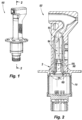
- FIG. 1 an illustrative view of an embodiment of a system in accordance with the disclosure is shown in Fig. 1 and is designated generally by reference character 100.
- FIG. 2-15 Other embodiments and/or aspects of this disclosure are shown in Figs. 2-15 .
- a system 100 can include, a housing assembly 102 and an element assembly 104.
- the element assembly 104 can include a dual-material component 200, 300 therein.
- the element assembly 104 can be joined to and within the housing assembly 102 via a weld joint 106 at a weld interface 108 between the dual-material component 200, 300 and the housing assembly 102.
- the system 100 can also include a base assembly 110, where the base assembly 110 is installed to the housing assembly 102 after the element assembly 104 is welded to the housing assembly 102 via the dual-material component 200, 300.
- the dual-material component can include an additively manufactured component portion 212, 312 and a base portion 214, 314, wherein the additively manufactured component portion 212, 312 is additively manufactured from a first material configured to manage heat within the housing assembly 102, and the base portion 214, 314 is manufactured from a second material, different than the first material.
- the second material can be a material compatible for welding with a material of the housing assembly 102.
- the first material may not be compatible for welding with the material of the housing assembly 102.
- the component portion 212, 312 may require certain metal properties of a material that is not necessarily compatible with the housing assembly 102. Therefore, the dual-material component 200, 300 can have the base portion 214, 314 be of a material compatible for welding with the housing assembly 102 to ensure both the component portion 212, 312 provides is desired properties but that the component 200, 300 as a whole can still be securely installed into the housing assembly 102.
- the metallic properties of the first and second materials can include, among other things: the first material can have a higher thermal conductivity than the second material. Material properties may also be selected to promote welding and brazing between components or transitioning between varying coefficients of thermal expansion.
- the dual-material component 200 can be a nickel-stainless steel component, where the additively manufactured component portion 212 is of nickel (e.g., nickel 200) and the base portion 214 is of stainless steel such that the base portion 214 provides a similar metal for welding to the housing assembly 102, which is of stainless steel, in embodiments.
- a method 400 of manufacturing the component 200 is described herein with respect to Figs. 4-11 .
- the dual-material component 300 can be a nickel-Inconel component, where the additively manufactured component portion 312 is of nickel (e.g., nickel 200) and the base portion 314 is of Inconel (e.g., Inconel 625), such that the base portion 214 provides a compatible metal for welding to the housing assembly 102, which is of stainless steel, in embodiments.
- the two dissimilar metals of stainless steel and Inconel 625 can be suitable for forming a compatible allow system at the weld interface.
- a method 500 of manufacturing the component 300 is described herein with respect to Figs. 12-15 .
- a method 400 of making a dual-material component includes, additively manufacturing 416 the component portion 212 from the first material onto a baseplate (e.g., the base portion 214) manufactured from the second material.
- Additive manufacturing 416 can include additively manufacturing using an energy source 418 to fuse metallic powder on a powder bed (e.g., laser powder bed fusion as shown in Fig. 4 .), or powder or wire ejected from a nozzle 420 with an energy beam 422 from the energy source (e.g., directed energy deposition shown in Fig. 12 .). Any suitable additive manufacturing technique is contemplated herein as would be appreciated by those having ordinary skill in the art in view of this disclosure.
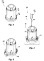
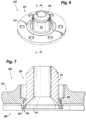
- the method 400 can further include machining 424 the base plate 214 to a predetermined geometry 426 corresponding to a component seat 428 within the housing assembly 102 (the component seat shown in Fig. 7 within a sensor base plate 431). After machining 424, the component 200 can take the form shown in Fig. 6 , where the diameter of the baseplate 214 matches a diameter of the component portion 212.
- the method 400 can further include, as shown in Fig.
- the method 400 can include separately manufacturing the base plate 214 from the second material, e.g., prior to additively manufacturing 416 the component portion 212 to the base plate 214.
- the method 400 can include producing a plurality of components 200 at the same time.
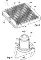
- the method 400 can also include manufacturing 432 a build plate 434 configured to hold one or more base plates 214 and installing the one or more base plates 214 into the build plate 434.
- manufacturing 432 the build plate can further include forming 436 a plurality of base plate recesses 438 in the build plate 434 and forming 440 a respective build plate bore 442 in each base plate recess 438 of the plurality of base plate recesses 438.
- manufacturing the base plate 214 can further include forming a respective base plate bore 444 in each base plate 214.
- the one or more base plates 214 can include a plurality of base plates 214
- the method 400 can further include installing 446 the plurality of base plates 214 into the build plate 434 can include, placing a respective base plate 214 into a respective base plate recess 438, and securing each respective base plate 214 to the build plate 434 in the respective base plate recess 438 with a respective fastener 448 extending through the respective base plate bore 444 and into the respective build plate bore 442.
- the method 400 can include additively manufacturing a plurality of components 200 of the first material onto each of the respective base plates 214 to manufacture a plurality of dual-material components 200 on the same build plate 434.
- a method 500 of manufacturing a dual-material component can include, additively manufacturing 516 the component portion 312 from a first material.
- Additive manufacturing 516 can be similar to additive manufacture 416, but additive manufacturing 516 can be remote to the rest of the method 500 and the component portion 312 can be manufactured on a conventional build plate, for example.
- the method 500 further includes cladding/directed energy deposition 550 the base portion 314 onto the component portion 312 to form the dual-material component 300 for use in the housing assembly 102.
- cladding 550 the base portion 314 onto the component portion 312 can include applying with a cladding nozzle 552, the second material to the component portion 312 to grow the base portion 314 from the component portion 312 to manufacture the dual-material component 300.
- the method 500 can further include, as shown in Fig. 13 , machining 524 the base portion 314 to a predetermined geometry 526 corresponding to a component seat 528 within the housing assembly 102 (the component seat shown in Fig. 15 within a sensor base plate 531). After machining 524, the component 300 can take the form shown in Fig. 14 , where the diameter of the baseplate 314 matches a diameter of the component portion 312.
- the method 500 can include, installing 529 the component 300 into the component seat 538 of the housing assembly 102, and welding 530 the base plate 314 of the component 300 to the housing assembly 102 at the weld interface 106 to form the weld joint 108 to secure the component 300 to the assembly 102.
- Nickel 200 has proven to provide superior thermal management properties for given applications, for example in air data sensing systems. However that same nickel 200 component (e.g., component 200, 300) needs to be laser welded to another stainless steel component (e.g., in the housing assembly 102). Nickel 200 and stainless steel are dissimilar metals that create a tricky weld which can be susceptible to hot cracking.
- the dual material component 200, 300 however, provides one material for thermal management (e.g., in the component portion 212, 312) and one for weldability (e.g., the base portion 214, 314), overcoming the noted challenges.
- methods 400 and 500 can use additive manufacturing to create a dual material component 200, 300 with a material transition to stainless steel or Inconel at the weld interface (e.g., a weld flange) creating a component with the required thermal management qualities and a robust and consistent weld.
- the material of the component could be nickel and the weld interface (e.g., base portion 214, 314) could be stainless steel or Inconel. Both are described herein.
- the dual material component 200 can be created using a stainless steel base material was attached to an additive manufacturing build plate. Then a nickel 200 component can be grown on top of the stainless steel base material. Next, the excess base material can be machined away creating the dual material component 200. This process is shown in Figs. 4-7 .
- This component 200 can have all the thermal properties required to perform well in heat and has a weld flange (e.g., base portion 214) of similar metals so it can be assembled easily and of high quality. The best quality weld would be stainless-steel to stainless-steel, thus in this embodiment, the base portion weld flange can be stainless steel.
- the nickel portion 212 of the component 200 is built in an inert environment and using a very precise set of laser welds. This produces a high quality weld with improved weld adhesion to the stainless steel build plate.
- nickel 200 component portion is able to be built onto the stainless steel base plate and allows provides for the similar metals (stainless to stainless) during the more difficult weld of welding the component 200 to the assembly.
- special build plates e.g., build plate 434
- stainless steel blanks e.g., base plates 2114
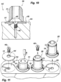
- Each potting well can be printed onto a blank which will limit the amount of wasted blank material and make post process machining easier and more consistent. This streamlined process is shown in Figs. 8-11 .
- the dual material component 300 can be created using am Inconel base material to for the weld flange so that the laser weld would be Inconel to stainless-steel when the component 300 is installed into the assembly 102.
- the method 500 for creating the component 300 using Inconel cladding can include first creating the main body of the component without the weld interface using any suitable method (e.g., additive manufacturing, casting). Next, Inconel material can be clad onto the main body and any excess cladded Inconel can be machined away. This can thus create the dual material potting well 300 that is of nickel 200 with an Inconel weld interface. This process is shown in Fig. 12-15 .
- dual material components 200, 300 can be produced having materials that maximize design performance while also producing high quality and repeatable weld interfaces. This can improve overall quality and minimize scrap while also reducing the difficulty of manufacturing.
- Embodiments include nickel 200 for the component portion 213, 312, as it has good thermal conductivity, anti-corrosion properties, it can be welded to Inconel 625 (which, in embodiments, is what the flow duct (the structure surrounding the potting well) is made from. Nickel 200 can also be additively manufactured, which is advantageous for manufacturing the complex design of the component portion 212, 312. Stainless steel and Inconel 625 can produce a very robust and repeatable laser beam weld between those two materials and the sensor baseplate 431, 531). A very high quality weld is required for that joint as it acts as a hermetic seal.
- a reference to "A and/or B", when used in conjunction with open-ended language such as “comprising” can refer, in one embodiment, to A only (optionally including elements other than B); in another embodiment, to B only (optionally including elements other than A); in yet another embodiment, to both A and B (optionally including other elements); etc.
Landscapes
- Engineering & Computer Science (AREA)
- Chemical & Material Sciences (AREA)
- Manufacturing & Machinery (AREA)
- Materials Engineering (AREA)
- Physics & Mathematics (AREA)
- Plasma & Fusion (AREA)
- Mechanical Engineering (AREA)
- Optics & Photonics (AREA)
- Thermal Sciences (AREA)
- Composite Materials (AREA)
- Laser Beam Processing (AREA)
- Connection Of Plates (AREA)
Applications Claiming Priority (1)
| Application Number | Priority Date | Filing Date | Title |
|---|---|---|---|
| US18/231,148 US20250050418A1 (en) | 2023-08-07 | 2023-08-07 | Dual-material components and methods of making therefor |
Publications (2)
| Publication Number | Publication Date |
|---|---|
| EP4506086A2 true EP4506086A2 (fr) | 2025-02-12 |
| EP4506086A3 EP4506086A3 (fr) | 2025-04-23 |
Family
ID=92264098
Family Applications (1)
| Application Number | Title | Priority Date | Filing Date |
|---|---|---|---|
| EP24193391.0A Pending EP4506086A3 (fr) | 2023-08-07 | 2024-08-07 | Composants à deux matériaux et leurs procédés de fabrication |
Country Status (2)
| Country | Link |
|---|---|
| US (1) | US20250050418A1 (fr) |
| EP (1) | EP4506086A3 (fr) |
Cited By (1)
| Publication number | Priority date | Publication date | Assignee | Title |
|---|---|---|---|---|
| EP4703068A1 (fr) * | 2024-08-30 | 2026-03-04 | Relativity Space, Inc. | Fabrication additive de structures hybrides |
Families Citing this family (2)
| Publication number | Priority date | Publication date | Assignee | Title |
|---|---|---|---|---|
| USD1110868S1 (en) * | 2024-02-09 | 2026-02-03 | Rosemount Aerospace Inc. | Aircraft total air temperature sensor |
| USD1110867S1 (en) * | 2024-02-09 | 2026-02-03 | Rosemount Aerospace Inc. | Aircraft total air temperature sensor |
Family Cites Families (4)
| Publication number | Priority date | Publication date | Assignee | Title |
|---|---|---|---|---|
| FR2951971B1 (fr) * | 2009-11-03 | 2011-12-09 | Michelin Soc Tech | Plateau de support pour dispositif de frittage laser et procede de frittage ameliore |
| US10493532B2 (en) * | 2017-01-17 | 2019-12-03 | General Electric Company | Thermal expansion fit build plate for additive manufacturing |
| US11826831B2 (en) * | 2020-01-10 | 2023-11-28 | Ford Global Technologies, Llc | Methods for additive manufacturing a part and parts formed according to the methods |
| WO2021258192A1 (fr) * | 2020-06-26 | 2021-12-30 | Safran Landing Systems Canada Inc. | Contrefiche de train d'atterrissage fabriquée par fabrication additive en utilisant un métal extrudé préformé comme matériau de base |
-
2023
- 2023-08-07 US US18/231,148 patent/US20250050418A1/en active Pending
-
2024
- 2024-08-07 EP EP24193391.0A patent/EP4506086A3/fr active Pending
Cited By (1)
| Publication number | Priority date | Publication date | Assignee | Title |
|---|---|---|---|---|
| EP4703068A1 (fr) * | 2024-08-30 | 2026-03-04 | Relativity Space, Inc. | Fabrication additive de structures hybrides |
Also Published As
| Publication number | Publication date |
|---|---|
| EP4506086A3 (fr) | 2025-04-23 |
| US20250050418A1 (en) | 2025-02-13 |
Similar Documents
| Publication | Publication Date | Title |
|---|---|---|
| EP4506086A2 (fr) | Composants à deux matériaux et leurs procédés de fabrication | |
| JP5943958B2 (ja) | セラミック断熱材料を金属構造体に接合するための構成 | |
| Dawes | Laser welding: a practical guide | |
| EP3345708B1 (fr) | Procédé d'amenée d'un matériel d'apport de brasure dans un joint, article brasé et ensemble pour brasage | |
| US6129257A (en) | High temperature brazing fixture | |
| EP2098324A1 (fr) | Joints à bout soudés sur des tubes entre des extrémités de raccordement présentant des profils différents | |
| CN209811451U (zh) | 热交换器元件 | |
| EP1875981A2 (fr) | Système, procédé et appareil pour joint structurel préformé métallique tissé tridimensionnel | |
| CN109759789A (zh) | 液体火箭发动机的推力室耐压夹层制造方法 | |
| EP2495065A2 (fr) | Procédé d'assemblage d'acier inoxydable | |
| US20190201995A1 (en) | Deposition of braze preform | |
| JP3457289B2 (ja) | レーザ溶接とtig溶接またはmig溶接との組合せによる厚板溶接方法 | |
| US10478920B2 (en) | Dual wall components for gas turbine engines | |
| US11420280B2 (en) | Closed socket brazed joint assembly | |
| JP5372436B2 (ja) | 金属部品のtig溶接への活性フラックスの使用 | |
| US7767318B2 (en) | Laser fillet welding | |
| CN111163884A (zh) | 用于桥接部件的系统和方法 | |
| CN116213866B (zh) | 一种异材金属接头焊接方法及异材焊接接头 | |
| EP3144505B1 (fr) | Composant de turbine à gaz et procédé de formation | |
| US12251769B2 (en) | Closed socket brazed joint assembly | |
| JP2017035721A (ja) | レーザ溶接継手 | |
| CN121576190A (zh) | 一种快速成形中空圆柱结构的复合制造方法 | |
| JPH064198B2 (ja) | 異種金属材料製配管接続用の継手部品の製造方法 | |
| JP2003275869A (ja) | 閉鎖容器の突合せ溶接方法 | |
| JPS63317255A (ja) | 密集多管の多孔金属部材への接合方法 |
Legal Events
| Date | Code | Title | Description |
|---|---|---|---|
| PUAI | Public reference made under article 153(3) epc to a published international application that has entered the european phase |
Free format text: ORIGINAL CODE: 0009012 |
|
| STAA | Information on the status of an ep patent application or granted ep patent |
Free format text: STATUS: THE APPLICATION HAS BEEN PUBLISHED |
|
| AK | Designated contracting states |
Kind code of ref document: A2 Designated state(s): AL AT BE BG CH CY CZ DE DK EE ES FI FR GB GR HR HU IE IS IT LI LT LU LV MC ME MK MT NL NO PL PT RO RS SE SI SK SM TR |
|
| PUAL | Search report despatched |
Free format text: ORIGINAL CODE: 0009013 |
|
| AK | Designated contracting states |
Kind code of ref document: A3 Designated state(s): AL AT BE BG CH CY CZ DE DK EE ES FI FR GB GR HR HU IE IS IT LI LT LU LV MC ME MK MT NL NO PL PT RO RS SE SI SK SM TR |
|
| RIC1 | Information provided on ipc code assigned before grant |
Ipc: B22F 12/30 20210101ALI20250318BHEP Ipc: B22F 7/06 20060101ALI20250318BHEP Ipc: B23K 15/00 20060101ALI20250318BHEP Ipc: B33Y 80/00 20150101ALI20250318BHEP Ipc: B33Y 10/00 20150101ALI20250318BHEP Ipc: B23K 26/342 20140101ALI20250318BHEP Ipc: B22F 10/28 20210101ALI20250318BHEP Ipc: B22F 10/25 20210101ALI20250318BHEP Ipc: B22F 7/08 20060101AFI20250318BHEP |
|
| STAA | Information on the status of an ep patent application or granted ep patent |
Free format text: STATUS: REQUEST FOR EXAMINATION WAS MADE |
|
| 17P | Request for examination filed |
Effective date: 20251023 |