EP4506098A1 - Verfahren und system zur laserbearbeitung von länglichen dünnen werkstücken mittels direktem laserschreiben - Google Patents
Verfahren und system zur laserbearbeitung von länglichen dünnen werkstücken mittels direktem laserschreiben Download PDFInfo
- Publication number
- EP4506098A1 EP4506098A1 EP23190876.5A EP23190876A EP4506098A1 EP 4506098 A1 EP4506098 A1 EP 4506098A1 EP 23190876 A EP23190876 A EP 23190876A EP 4506098 A1 EP4506098 A1 EP 4506098A1
- Authority
- EP
- European Patent Office
- Prior art keywords
- workpiece
- laser
- mirror
- laser beam
- optical sub
- Prior art date
- Legal status (The legal status is an assumption and is not a legal conclusion. Google has not performed a legal analysis and makes no representation as to the accuracy of the status listed.)
- Withdrawn
Links
Images

Classifications
-
- B—PERFORMING OPERATIONS; TRANSPORTING
- B23—MACHINE TOOLS; METAL-WORKING NOT OTHERWISE PROVIDED FOR
- B23K—SOLDERING OR UNSOLDERING; WELDING; CLADDING OR PLATING BY SOLDERING OR WELDING; CUTTING BY APPLYING HEAT LOCALLY, e.g. FLAME CUTTING; WORKING BY LASER BEAM
- B23K26/00—Working by laser beam, e.g. welding, cutting or boring
- B23K26/08—Devices involving relative movement between laser beam and workpiece
- B23K26/082—Scanning systems, i.e. devices involving movement of the laser beam relative to the laser head
-
- B—PERFORMING OPERATIONS; TRANSPORTING
- B23—MACHINE TOOLS; METAL-WORKING NOT OTHERWISE PROVIDED FOR
- B23K—SOLDERING OR UNSOLDERING; WELDING; CLADDING OR PLATING BY SOLDERING OR WELDING; CUTTING BY APPLYING HEAT LOCALLY, e.g. FLAME CUTTING; WORKING BY LASER BEAM
- B23K26/00—Working by laser beam, e.g. welding, cutting or boring
- B23K26/08—Devices involving relative movement between laser beam and workpiece
- B23K26/0823—Devices involving rotation of the workpiece
-
- B—PERFORMING OPERATIONS; TRANSPORTING
- B23—MACHINE TOOLS; METAL-WORKING NOT OTHERWISE PROVIDED FOR
- B23K—SOLDERING OR UNSOLDERING; WELDING; CLADDING OR PLATING BY SOLDERING OR WELDING; CUTTING BY APPLYING HEAT LOCALLY, e.g. FLAME CUTTING; WORKING BY LASER BEAM
- B23K26/00—Working by laser beam, e.g. welding, cutting or boring
- B23K26/08—Devices involving relative movement between laser beam and workpiece
- B23K26/083—Devices involving movement of the workpiece in at least one axial direction
- B23K26/0838—Devices involving movement of the workpiece in at least one axial direction by using an endless conveyor belt
- B23K26/0846—Devices involving movement of the workpiece in at least one axial direction by using an endless conveyor belt for moving elongated workpieces longitudinally, e.g. wire or strip material
-
- B—PERFORMING OPERATIONS; TRANSPORTING
- B23—MACHINE TOOLS; METAL-WORKING NOT OTHERWISE PROVIDED FOR
- B23K—SOLDERING OR UNSOLDERING; WELDING; CLADDING OR PLATING BY SOLDERING OR WELDING; CUTTING BY APPLYING HEAT LOCALLY, e.g. FLAME CUTTING; WORKING BY LASER BEAM
- B23K26/00—Working by laser beam, e.g. welding, cutting or boring
- B23K26/20—Bonding
- B23K26/21—Bonding by welding
- B23K26/24—Seam welding
- B23K26/28—Seam welding of curved planar seams
- B23K26/282—Seam welding of curved planar seams of tube sections
Definitions
- the present invention relates to laser processing technology, specifically to a method of laser energy delivery on elongated thin workpieces (for example, cylindrically-shaped, or having quadrilateral or mullitlateral perpendicular cross-section) with diameters, preferably, less than 2 mm, that can be applicable including but not limited to precision-laser-cutting, laser stripping, selective surface micro/nanopatterning, stent fabrication, thinning of dielectric and metallic materials by the means of direct laser writing techniques.
- elongated thin workpieces for example, cylindrically-shaped, or having quadrilateral or mullitlateral perpendicular cross-section
- diameters preferably, less than 2 mm
- Ultrafast laser micromachining is a precision manufacturing technique that utilizes high-intensity, ultrashort laser pulses to create intricate features and patterns on various materials at a microscopic scale.
- the process involves focusing the ultrafast laser beam onto the target material while the high peak power of the laser pulses removes material through a combination of mechanisms, including ablation, material modification, melting, and vaporization.
- DLW direct laser writing
- DLW means the workpiece surface processing method where each surface region can be directly accessed by focused laser radiation, meaning that each workpiece surface region has unique sets of coordinates and the laser radiation is initiated only at particular coordinates that can be dynamically changed by the operator, producing discrete or continuous free-form shapes that were laser irradiated.
- the desired outcome of DLW applications depends on the suitable choice of fabrication parameters, which include but are not limited to radiation parameters, focusing conditions, and recording and patterning algorithms, which in general are material-sensitive and can be experimentally evaluated or estimated from scientific literature by the person skilled in this art.
- a laser machining system implements synchronized beam scanning with linear sample translation that can cover large workpiece areas for DLW tasks.
- a design is suited only for flat workpieces, while shapes with higher surface complexity will require more sophisticated beam focus positioning.
- DLW on cylindrical-shaped workpieces is an important fabrication tool for R&D and industry.
- the ability to perform DLW in a continuous process across all workpiece surface, in which the workpiece is continuously passed through a laser processing device while DLW operation is carried out with laser radiation at the respective intended locations, is highly valuable.
- a challenge for this type of processing is the requirement that the sample be processed on all sides and evenly.
- a similar problem often arises with laser welding of cylindrical workpieces, soldering, and wire stripping operations.
- three processing strategies can be generalized for cylindrical shape laser microprocessing: (I) laser turning based solutions with rotative workpiece, (II) rotating/flying optics designs, (III) multibeam processing.
- the apparatus setup resembles a mechanical turning lathe, but instead of a chisel, a focused ultrashort pulsed laser beam is used.
- the laser beam is positioned perpendicular to the rotational axis and guided along the workpiece to create rotationally symmetric parts.
- patent documents US8383981B2 , US2005/0058947A1 the apparatuses are presented where the complete area of cylindrical workpiece is accessible for laser processing by the means of controlled sample rotation.
- the international patent application WO2020/098868A1 discloses an apparatus for laser cutting of shielding conductors that utilizes sequential multibeam focusing realized using a single deflecting mirror.
- a symmetrical optical configuration with up to 8 beam paths is chosen where focused laser radiation terminates perpendicularly on the cylindrical workpiece. The symmetry is maintained by propagating the laser beam along the workpiece with the scanning axis coinciding with the workpiece axis, while only the final mirrors fold the beam perpendicularly to the surface.
- a drawback of prior art is that long cylindrical objects cannot be processed with this apparatus because eventually the laser beam will be obstructed by the workpiece's presence. Additionally, right-angle mirrors acting on the converging laser introduce a high level of astigmatism, reducing the size of the focal spot on the surface.
- the present invention is therefore based on the object of developing the machining device in such a way that the disadvantages described above can be avoided.
- a focal spot size at all processing phases should be diffraction-limited, which will improve the processing resolution of the laser machining task.
- the DLW parameters can be set independently on the processing side.
- the invention can also be used to machine profiled and/or asymmetrical workpieces.
- the objective of the invention is achieved by the optomechanical system that includes a series of mirrors and focusing optics arranged in a symmetrical paraxial optical configuration that can redirect and focus a laser beam on four opposite sides in an orthogonal configuration on a cylindrical workpiece surface with diffraction-limited resolution, which is the first aspect of the invention.
- a method of machining elongated thin workpieces for example, thin cylindrical, or having quadrangular, or multiangular crossection
- DLW a single laser scanner
- a laser beam generated preferably but not limited to, from an ultrashort laser pulse generator that has automated internal or external power attenuation and shutter, is directed through optional beam conditioning optical devices, preferably the optical telescope, to a computer-controlled optical scanner, which deflects the laser beam at predefined angles to the designated optical subsystems, each one consisting of several mirrors and one final focusing element, arranged in such a way that the laser beam enters the focusing element at low angles complying with the paraxial optics requirement and terminates at the target, which is a focus position.
- optional beam conditioning optical devices preferably the optical telescope
- a computer-controlled optical scanner which deflects the laser beam at predefined angles to the designated optical subsystems, each one consisting of several mirrors and one final focusing element, arranged in such a way that the laser beam enters the focusing element at low angles complying with the paraxial optics requirement and terminates at the target, which is a focus position.
- four optical subsystems in orthogonal configurations are used, but their number is not
- All focusing points should preferably converge on a single point, which is the cylindrical axis of the workpiece.
- Each optical subsystem is accessible separately by setting a different scanning angle, while continuous scanning across the workpiece is realized in each optical subsystem independently by setting the scanner wobbling amplitude.
- the working field of the subsystem depends on the focusing optics parameters and the distance from the scanner mirror to the focusing element and is limited by the paraxial condition requirement. While this requirement is satisfied, focusing optics have aberration-free imaging, and f-theta configuration is satisfied by definition, avoiding the need for complex focusing optical systems.
- the orthogonal beam intersection at the workpiece allows the processing of only a quarter of the workpiece with a single optical subsystem, while the field of view equals half the workpiece, which allows the smooth overlap of focal positions across all sides.
- Operator could choose either to work at normal laser incident configuration, which means that the laser beam hits the workpiece at perpendicular orientation, producing the smallest focus size preferable for precision micropatterning or cutting, or operate at tangential orientation, where the beam focus barely skips the edge of the workpiece, better suited for polishing and thinning applications.
- the optical path in each subsystem has mirror-like symmetry and has identical optical path length, which allows integration of additional beam conditioning optical elements before the scanner devices.
- Beam-shaping optical devices such as a cylindrical telescope that converts a Gaussian beam spot to a cylindrical-shaped focal spot, a collimated axicon for Gaussian-Bessel beam profile generation that helps to extend focusing depth, or similar devices can be readily integrated by a person skilled in this art.
- the workpiece is translated through processing equipment, specifically through the processing area, while the DLW is in operation.
- the feed rate, laser generation, and scanner position are synchronized using a computer.
- the translation rate can be either constant or variable. In the latter case, the feed rate changes during the machining process of the workpiece.
- a rotational operation can be used together with translation to increase speed and DLW precision.
- the invention is not limited to a particular DLW method but may involve any type of surface treatment, including stripping, thinning, annealing, welding, selective cutting, marking, or cleaning, among others.
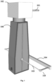
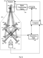
- an apparatus for the laser processing of elongated thin, for example, cylindrically-shaped or having quadrilateral or mullitlateral or elliptic perpendicular cross-section, workpieces comprises the main unit 100, which is attached to a scanner device 102 that deflects the laser beam 101 according to the chosen processing protocol.
- the scanner device 102 comprises single or double mirror components, termed the “scanner head" (204), which accepts computer-controlled commands and deflects the mirror at angles corresponding to these commands, deflecting the incoming laser beam.
- the operation principle of the scanner head is known to a person skilled in the art and will not be discussed in detail at this point.
- the scanner head 204 deflects the laser beam at a predefined angle, which enters the main unit and, more specifically, one of the several optical subsystems present in the main unit, which are indicated in Figure 2a .
- four subsystems are shown. These subsystems comprise several folded mirrors: subsystem (I) includes flat mirrors 205, 206 and spherical mirror 207, subsystem (II) includes flat mirrors 208, 209 and spherical mirror 210, subsystem (III) includes flat mirror 211 and spherical mirror 212, and subsystem (IV) includes flat mirror 213 and spherical mirror 214 as depicted in Figure 2b .
- All the spherical mirrors have identical surface curvature and are in symmetric arrangement at opposite sides of the workpiece 103, producing the beam waist directly on the workpiece 103 in the orthogonal configuration.
- the laser beam will enter each subsystem in such a way that it will be centered on the spherical mirror (207, 210, 212, 214).
- the arrangement of the flat mirror prior to the spherical mirror is such that the incident angle of the directed laser beam on the spherical mirror remains small.
- each of the spherical mirrors (207, 210, 212, 214) is paired with a flat auxiliary mirror (206, 209, 211, 213) that corrects the incident angle on the spherical mirror to produce close-to-normal reflection, which capacitates the paraxial propagation regime, mitigating optical aberrations of the laser beam.
- the minimum incident angle is limited by the diameter of the used mirrors and mirror holder dimensions, the focal distance, and the workpiece size. It is clear that the optical system can be rearranged by shifting auxiliary mirror positions in such a way that optical paths in all subsystems are equidistant with identical incident angles on focusing mirrors. In this configuration, each subsystem will have identical optical performance with the minimum amount of optical aberration, implying that a collimated laser beam enters the scanner.
- the scanner can be programmed to additionally deflect the laser beam in the subsystem according to a predefined algorithm, which will result in the shifting of the focal spot position with respect to the workpiece surface, facilitating DLW operation.
- the movement of the focal position is mainly caused by the change in incidence angle on the spherical mirror, which linearly correlates with scanner angle, facilitating the f-theta working condition. This means that a linear change in scanner angle produces a proportional shift in focal position on the workpiece, which allows direct application of the DLW process without elaborate calibration.
- the minor change in scanner angle will shift the laser beam off-center on the spherical mirror, which will cause additional aberrations to appear.
- these aberrations can be neglected if the incident angle remains small and obeys the paraxial beam propagation regime.
- this condition will be satisfied for focal shift movement in a range of 2 mm on the workpiece surface, defining the aberration-free working field of a single subsystem. Combining all subsystems, the working field will cover a full cylindrical workpiece with a 2 mm cross section.
- the workpiece 103 to be processed is not a part of the main unit and is attached with external holders from both sides to the automatized translation stage 104.
- the external holders can be adjusted in such a way that the workpiece 103 axis will coincide with the common focal axis of the main unit 105, while the beam propagation direction in the main unit 100 will be perpendicular to the workpiece 103 axis. In this way, the workpiece 103 can be fed into the apparatus to provide continuous DLW processing.
- the direction of the feed, feed speed, and feed type i.e. continuous movement or movement in discrete steps, can be programmed by a translation stage, known by the person skilled in the art.
- the confocal parameter of the focused laser beam for >100 mm focal length mirror will be comparable to the workpiece diameter, therefore, it is preferable to align all subsystems at one central point 105, termed the main unit 100 axis where workpiece 103 is located.
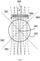
- Figure 3 shows the target location where regions 301, 302, 303 and 304 depict the regions accessible with separate subsystem. For the 301 region, a possible scanning trajectory for line processing using DLW is depicted.
- An original laser focus 305 is located directly at the workpiece center, which corresponds to on-axis position of particular spherical mirror. When the beam is deflected within the subsystem, the beam travels across the center of the workpiece, tracing line 306 on the workpiece surface facilitating DLW operation.
- a particular advantage of such embodiment is that the focal positions for all subsystems are permanently fixed at single point at the initial assembly stage and do not need further adjustments.
- the tradeoff of such configuration is that, due to the sample curvature, the central beam and shifted beam hit the target at different angles, meaning that complete beam uniformity on the surface cannot be achieved. However, this tradeoff can be compensated by varying beam density across the scanning direction. It is understandable, that for complete processing of the full cylindrical surface, this operation must be performed with all subsystems.
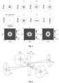
- Figure 5 presents the estimated aberrations for separate subsystems and scanning positions in each subsystem.
- ⁇ SFA 0.0078/( f / # )) 3 , where ⁇ SFA is the blur angle (in rad) measured from exit pupil, which in this case coincides with the focusing mirror.
- f/# is defined as the ratio of lens focal length to aperture, which for typical 100 mm focal length mirror in our main unit is a high value (> 20), while u p is the incidence angle.
- ⁇ 1.22 ⁇ f /#.
- the spot patterns are reversed in II and IV subsystems due to inversion of incidence angle, also the subsystems III and IV show slightly larger aberrations. This is because incidence angles were set to be slightly bigger for these subsystems than I and II. This can be corrected if needed by shifting mirrors 211 and 213 closer to the corresponding mirrors 207 and 210.
- the middle part of Figure 5 shows the spot diagrams when sample scans across the subsystem.
- the left diagram shows the footprint on 1.4 mm size target while laser is focused on the sample center A and edges B, C.
- Corresponding spot diagrams are shown on the right.
- the Gaussian beam distribution is modeled at A,B,C locations, showing that peak intensity in all three locations matches with 90 % precision.
- the DLW is performed on the workpiece 103 by the following steps.
- a computer 201 is used to prepare required DLW algorithm which includes the set of coordinates and timing commands in predefine sequence and sends these commands to laser generator 202 for setting laser generation parameters such as starting or stopping of generation, changing laser power or any other parameter that can be changed by externally controlled signal, and positioning devices, which are scanner head 102 and translation stage 104.
- laser generator 202 for setting laser generation parameters such as starting or stopping of generation, changing laser power or any other parameter that can be changed by externally controlled signal, and positioning devices, which are scanner head 102 and translation stage 104.
- main unit construction and scanning head will capacitate such electromagnetic radiation that matches mirror reflective coatings, therefore laser radiation with wavelengths from far IR, generated i.e. from CO2 lasers, up to excimer laser operating at deep UV wavelengths can be used.
- Deep UV wavelength at 257 nm was chosen as preferred source for this embodiment.
- different laser operating regimes such as continuous wave, pulsed lasers, or burst laser can be used as the light sources for the apparatus.
- controlling commands can differ.
- DLW with ultrafast laser sources are preferred therefore laser generator will be able to generate ultrashort laser pulses at particular instance indicated by computer control command with additional parameters such as the number of pulses, pulse duration, the pulse energy, or any additional parameter required for particular DLW operation.
- the emitted laser pulses can be additionally modified with optional beam conditioning optics module 203 before entering the scanner and main unit.
- the positioning commands control the scanner deflection angle, which direct laser beam to particular working field position across the workpiece while translation commands feed the workpiece into the working field of the apparatus.
- each location on cylindrical workpiece can be located in translation stage traveling range.
- skilled operator can employ automatic workpiece holders 104, i.e. electromagnetic clamps, that are released when translation stage reaches its limits, then the workpiece is pulled by predefined amount with some external apparatus, i.e. flexible workpiece can be rotated on the bin that holds processed workpiece, enabling of processing workpieces with unlimited length.
- Feedback signals from the scanner and translation stages that encode present coordinates, and the state of the devices can be utilized for optimization DLW algorithm by skilled operator.
- workpiece positioning can also include other degrees of freedom, i.e. the workpiece rotation along its axis and angular coordinates can be additional positioning variables for DLW applications.
- a machine vision camera with microscope objective 215 can be installed for process monitoring tasks in real time at the opposite-from-scanner side where free-of-beam zone are located which will cover the half size of the processing zone.
- Other identical camera can be installed on opposite site at the slight angle to workpiece in-order not to obstruct the laser beam, that will cover the other half of the workpiece (not shown in Figure 2 ). As the beam propagates almost entirely in one plane in the main unit, it is straightforward to install additional cameras if necessary close to workpieces at the slightly tilted planes in embodiments where detailed visual process control is needed.
- DLW algorithm may look as fallows: (I) deflect the scanner to the edge of first subsystem (corresponding to the far left edge of region 301) and generat ten laser pulses on the designated spot, (II) shift the scanner by specific angle (typical in range 10 ⁇ rad), and repeat the laser writing, (III) repeat the same procedure again until the right edge of region 301 is reached; (IV) then scanner is deflected to other closest subsystem (typical in range 30 - 100 mrad) and the algorithm in steps I-III is repeated; (V) the DLW for remaining two subsystems is repeated in the same fashion, (VI) the translation stage moves sample by designated distance and process is repeated until algorithm ends.
- This is a most straightforward algorithm that could be used as blueprint for other DLW development. However, it is not optimal in the processing speed sense other solutions are possible and will
- the scanner shifting between the subsystems can be entirely eliminated with multibeam accessory 203 shown in Figure 4 .
- DOE diffractive optics element
- Such elements are commercially available and can be ordered with parameters suitable for particular laser wavelength and separation angle.
- the 4f imaging system is installed with telescope consisting of lenses 402 and 403 that images DOE on the scanner head 204.
- the four laser beams at symmetrical angles will exit the scanner where each of the beam can be arranged to be the center of the subsystem.
- the scanning for a single subsystem will result in scanning in all four subsystems simultaneously increasing processing speed.
- X which is set as perpendicular to workpiece
- Y which is set as parallel to workpiece
- Y axis aberration considerations are identical as for X axis, meaning that single subsystem will have 2 mm x 2 mm working field, that can be efficiently applied to increase DLW throughput.
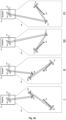
- the presence of Y axis can be incorporated in the algorithm as additional coordinate for DLW increasing the feeding rate of translation stage as shown in Figure 6 .
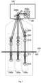
- additional main unit or units can be installed along the workpiece, where each subsystems are accessed by particular X and Y deflection angle combination as shown in Figure 7 .
- Scanner mirror 204a deflects the laser beam in X direction accessing subsystem within the main unit while mirror 204b deflects the beam along the workpiece to the additional units.
- Additional units may have identical optical subsystems 100b as the prime main unit 100a or may have different layout in example with spherical mirrors having different focal lengths 100c, producing bigger focused beam spot.
- the additional units and subsystem within them can be accessed by DLW algorithm providing the scanner position commands.
Landscapes
- Physics & Mathematics (AREA)
- Optics & Photonics (AREA)
- Engineering & Computer Science (AREA)
- Plasma & Fusion (AREA)
- Mechanical Engineering (AREA)
- Laser Beam Processing (AREA)
Priority Applications (1)
| Application Number | Priority Date | Filing Date | Title |
|---|---|---|---|
| EP23190876.5A EP4506098A1 (de) | 2023-08-10 | 2023-08-10 | Verfahren und system zur laserbearbeitung von länglichen dünnen werkstücken mittels direktem laserschreiben |
Applications Claiming Priority (1)
| Application Number | Priority Date | Filing Date | Title |
|---|---|---|---|
| EP23190876.5A EP4506098A1 (de) | 2023-08-10 | 2023-08-10 | Verfahren und system zur laserbearbeitung von länglichen dünnen werkstücken mittels direktem laserschreiben |
Publications (1)
| Publication Number | Publication Date |
|---|---|
| EP4506098A1 true EP4506098A1 (de) | 2025-02-12 |
Family
ID=87567589
Family Applications (1)
| Application Number | Title | Priority Date | Filing Date |
|---|---|---|---|
| EP23190876.5A Withdrawn EP4506098A1 (de) | 2023-08-10 | 2023-08-10 | Verfahren und system zur laserbearbeitung von länglichen dünnen werkstücken mittels direktem laserschreiben |
Country Status (1)
| Country | Link |
|---|---|
| EP (1) | EP4506098A1 (de) |
Cited By (2)
| Publication number | Priority date | Publication date | Assignee | Title |
|---|---|---|---|---|
| CN120190489A (zh) * | 2025-04-15 | 2025-06-24 | 广东工业大学 | 一种基于折射-反射激光束收集系统的双光路切割方法 |
| GB2638875A (en) * | 2024-02-12 | 2025-09-03 | Laser Wire Solutions Ltd | Laser wire stripper |
Citations (13)
| Publication number | Priority date | Publication date | Assignee | Title |
|---|---|---|---|---|
| US4671848A (en) | 1984-12-17 | 1987-06-09 | General Laser, Inc. | Method for laser-induced removal of a surface coating |
| FR2690015A1 (fr) | 1992-04-10 | 1993-10-15 | Eurocopter France | Dispositif pour dénuder des câbles ou analogues, par laser. |
| US6091533A (en) * | 1997-07-11 | 2000-07-18 | Asahi Kogaku Kogyo Kabushiki Kaisha | Reflection type scanning optical system |
| US6423929B1 (en) | 1998-07-14 | 2002-07-23 | Siemens Aktiengesellschaft | Device for the laser processing of flat workpieces |
| JP2004102268A (ja) * | 2002-08-21 | 2004-04-02 | Pentax Corp | 走査光学系の生産方法 |
| US20050058947A1 (en) | 2003-09-11 | 2005-03-17 | Rinehart Thomas A. | Systems and methods for fabricating optical microstructures using a cylindrical platform and a rastered radiation beam |
| US20070151959A1 (en) | 2005-12-30 | 2007-07-05 | Hon Hai Precision Industry Co., Ltd. | Device for stripping outer covering of cable |
| WO2007125677A1 (ja) * | 2006-04-26 | 2007-11-08 | Phoeton Corp. | シールド導体層の切断方法及びレーザ加工装置 |
| WO2008084216A1 (en) | 2007-01-08 | 2008-07-17 | Spectrum Technologies Plc | Laser wire strippers |
| US8383981B2 (en) | 2007-11-16 | 2013-02-26 | 3M Innovative Properties Company | Seamless laser ablated roll tooling |
| CN103706946A (zh) * | 2013-12-03 | 2014-04-09 | 张立国 | 一种激光分束振镜扫描加工装置 |
| EP3603872A1 (de) | 2018-07-30 | 2020-02-05 | Clean Lasersysteme GmbH | Vorrichtung und verfahren zum bearbeiten eines werkstücks mittels laserstrahlung |
| WO2020098868A1 (de) | 2018-11-16 | 2020-05-22 | Md Elektronik Gmbh | Laserschneidevorrichtung für geschirmte leitungen und verfahren zum laserschneiden von geschirmten leitungen mit einer solchen laserschneidevorrichtung |
-
2023
- 2023-08-10 EP EP23190876.5A patent/EP4506098A1/de not_active Withdrawn
Patent Citations (13)
| Publication number | Priority date | Publication date | Assignee | Title |
|---|---|---|---|---|
| US4671848A (en) | 1984-12-17 | 1987-06-09 | General Laser, Inc. | Method for laser-induced removal of a surface coating |
| FR2690015A1 (fr) | 1992-04-10 | 1993-10-15 | Eurocopter France | Dispositif pour dénuder des câbles ou analogues, par laser. |
| US6091533A (en) * | 1997-07-11 | 2000-07-18 | Asahi Kogaku Kogyo Kabushiki Kaisha | Reflection type scanning optical system |
| US6423929B1 (en) | 1998-07-14 | 2002-07-23 | Siemens Aktiengesellschaft | Device for the laser processing of flat workpieces |
| JP2004102268A (ja) * | 2002-08-21 | 2004-04-02 | Pentax Corp | 走査光学系の生産方法 |
| US20050058947A1 (en) | 2003-09-11 | 2005-03-17 | Rinehart Thomas A. | Systems and methods for fabricating optical microstructures using a cylindrical platform and a rastered radiation beam |
| US20070151959A1 (en) | 2005-12-30 | 2007-07-05 | Hon Hai Precision Industry Co., Ltd. | Device for stripping outer covering of cable |
| WO2007125677A1 (ja) * | 2006-04-26 | 2007-11-08 | Phoeton Corp. | シールド導体層の切断方法及びレーザ加工装置 |
| WO2008084216A1 (en) | 2007-01-08 | 2008-07-17 | Spectrum Technologies Plc | Laser wire strippers |
| US8383981B2 (en) | 2007-11-16 | 2013-02-26 | 3M Innovative Properties Company | Seamless laser ablated roll tooling |
| CN103706946A (zh) * | 2013-12-03 | 2014-04-09 | 张立国 | 一种激光分束振镜扫描加工装置 |
| EP3603872A1 (de) | 2018-07-30 | 2020-02-05 | Clean Lasersysteme GmbH | Vorrichtung und verfahren zum bearbeiten eines werkstücks mittels laserstrahlung |
| WO2020098868A1 (de) | 2018-11-16 | 2020-05-22 | Md Elektronik Gmbh | Laserschneidevorrichtung für geschirmte leitungen und verfahren zum laserschneiden von geschirmten leitungen mit einer solchen laserschneidevorrichtung |
Cited By (2)
| Publication number | Priority date | Publication date | Assignee | Title |
|---|---|---|---|---|
| GB2638875A (en) * | 2024-02-12 | 2025-09-03 | Laser Wire Solutions Ltd | Laser wire stripper |
| CN120190489A (zh) * | 2025-04-15 | 2025-06-24 | 广东工业大学 | 一种基于折射-反射激光束收集系统的双光路切割方法 |
Similar Documents
| Publication | Publication Date | Title |
|---|---|---|
| US6285002B1 (en) | Three dimensional micro machining with a modulated ultra-short laser pulse | |
| KR102132846B1 (ko) | 표면을 레이저 가공하기 위한 가공 장치 및 방법 | |
| JP4820071B2 (ja) | マルチビーム微細加工システムおよびその方法 | |
| EP4506098A1 (de) | Verfahren und system zur laserbearbeitung von länglichen dünnen werkstücken mittels direktem laserschreiben | |
| CN111992873B (zh) | 用于射束成形的光学系统 | |
| CN107027325B (zh) | 衍射光学射束成形元件 | |
| EP1271219B1 (de) | Laser-Strahlführungssystem mit Bohr-Modul | |
| US6635849B1 (en) | Laser beam machine for micro-hole machining | |
| JP6159428B2 (ja) | レーザ加工システム及び方法 | |
| CN107073645B (zh) | 具有平行错位单元的激光材料加工设备 | |
| KR20190104331A (ko) | 추가 레이저 기계가공 시스템 및 방법 | |
| KR20150126603A (ko) | 테이퍼 제어를 위한 빔 각도 및 작업물 이동의 공조 | |
| JP2023552942A (ja) | レーザ加工システムおよび方法 | |
| US20190118305A1 (en) | Laser 3d processing system | |
| KR102743129B1 (ko) | 레이저 빔의 에너지 분포 제어 모듈, 이를 사용하는 제어 방법 및 이를 포함하는 레이저 가공 시스템 | |
| JP7452901B2 (ja) | レーザ加工装置 | |
| US20230330782A1 (en) | Device for machining a material | |
| RU2283738C1 (ru) | Установка для лазерной обработки | |
| JP2007029959A (ja) | レーザ加工機 | |
| KR20190056895A (ko) | 미세 패턴 정밀 가공 장치 | |
| CN114401813A (zh) | 激光打孔装置 | |
| JPH05220189A (ja) | レーザビームによるアブレーション装置 | |
| GB2629349A (en) | Apparatus and method for directing laser radiation onto a target, laser drilling apparatus and method | |
| JP2006015402A (ja) | 材料加工用の複数の独立偏向可能なレーザービームを発生及び制御するためのシステム及び方法 | |
| KR20070031264A (ko) | 유연한 스캔 영역 |
Legal Events
| Date | Code | Title | Description |
|---|---|---|---|
| PUAI | Public reference made under article 153(3) epc to a published international application that has entered the european phase |
Free format text: ORIGINAL CODE: 0009012 |
|
| STAA | Information on the status of an ep patent application or granted ep patent |
Free format text: STATUS: THE APPLICATION HAS BEEN PUBLISHED |
|
| AK | Designated contracting states |
Kind code of ref document: A1 Designated state(s): AL AT BE BG CH CY CZ DE DK EE ES FI FR GB GR HR HU IE IS IT LI LT LU LV MC ME MK MT NL NO PL PT RO RS SE SI SK SM TR |
|
| STAA | Information on the status of an ep patent application or granted ep patent |
Free format text: STATUS: THE APPLICATION IS DEEMED TO BE WITHDRAWN |
|
| 18D | Application deemed to be withdrawn |
Effective date: 20250813 |