EP4506122A1 - Méthode de découpe, de refoulage et/ou de gaufrage d'un carton et machine de traitement du carton - Google Patents
Méthode de découpe, de refoulage et/ou de gaufrage d'un carton et machine de traitement du carton Download PDFInfo
- Publication number
- EP4506122A1 EP4506122A1 EP23191035.7A EP23191035A EP4506122A1 EP 4506122 A1 EP4506122 A1 EP 4506122A1 EP 23191035 A EP23191035 A EP 23191035A EP 4506122 A1 EP4506122 A1 EP 4506122A1
- Authority
- EP
- European Patent Office
- Prior art keywords
- cardboard
- cardboard web
- cutting
- creasing
- printed
- Prior art date
- Legal status (The legal status is an assumption and is not a legal conclusion. Google has not performed a legal analysis and makes no representation as to the accuracy of the status listed.)
- Pending
Links
Images
Classifications
-
- B—PERFORMING OPERATIONS; TRANSPORTING
- B31—MAKING ARTICLES OF PAPER, CARDBOARD OR MATERIAL WORKED IN A MANNER ANALOGOUS TO PAPER; WORKING PAPER, CARDBOARD OR MATERIAL WORKED IN A MANNER ANALOGOUS TO PAPER
- B31F—MECHANICAL WORKING OR DEFORMATION OF PAPER, CARDBOARD OR MATERIAL WORKED IN A MANNER ANALOGOUS TO PAPER
- B31F1/00—Mechanical deformation without removing material, e.g. in combination with laminating
- B31F1/07—Embossing, i.e. producing impressions formed by locally deep-drawing, e.g. using rolls provided with complementary profiles
-
- B—PERFORMING OPERATIONS; TRANSPORTING
- B26—HAND CUTTING TOOLS; CUTTING; SEVERING
- B26D—CUTTING; DETAILS COMMON TO MACHINES FOR PERFORATING, PUNCHING, CUTTING-OUT, STAMPING-OUT OR SEVERING
- B26D5/00—Arrangements for operating and controlling machines or devices for cutting, cutting-out, stamping-out, punching, perforating, or severing by means other than cutting
-
- B—PERFORMING OPERATIONS; TRANSPORTING
- B26—HAND CUTTING TOOLS; CUTTING; SEVERING
- B26D—CUTTING; DETAILS COMMON TO MACHINES FOR PERFORATING, PUNCHING, CUTTING-OUT, STAMPING-OUT OR SEVERING
- B26D5/00—Arrangements for operating and controlling machines or devices for cutting, cutting-out, stamping-out, punching, perforating, or severing by means other than cutting
- B26D5/20—Arrangements for operating and controlling machines or devices for cutting, cutting-out, stamping-out, punching, perforating, or severing by means other than cutting with interrelated action between the cutting member and work feed
-
- B—PERFORMING OPERATIONS; TRANSPORTING
- B26—HAND CUTTING TOOLS; CUTTING; SEVERING
- B26D—CUTTING; DETAILS COMMON TO MACHINES FOR PERFORATING, PUNCHING, CUTTING-OUT, STAMPING-OUT OR SEVERING
- B26D7/00—Details of apparatus for cutting, cutting-out, stamping-out, punching, perforating, or severing by means other than cutting
- B26D7/18—Means for removing cut-out material or waste
-
- B—PERFORMING OPERATIONS; TRANSPORTING
- B26—HAND CUTTING TOOLS; CUTTING; SEVERING
- B26F—PERFORATING; PUNCHING; CUTTING-OUT; STAMPING-OUT; SEVERING BY MEANS OTHER THAN CUTTING
- B26F1/00—Perforating; Punching; Cutting-out; Stamping-out; Apparatus therefor
- B26F1/38—Cutting-out; Stamping-out
- B26F1/384—Cutting-out; Stamping-out using rotating drums
-
- B—PERFORMING OPERATIONS; TRANSPORTING
- B31—MAKING ARTICLES OF PAPER, CARDBOARD OR MATERIAL WORKED IN A MANNER ANALOGOUS TO PAPER; WORKING PAPER, CARDBOARD OR MATERIAL WORKED IN A MANNER ANALOGOUS TO PAPER
- B31F—MECHANICAL WORKING OR DEFORMATION OF PAPER, CARDBOARD OR MATERIAL WORKED IN A MANNER ANALOGOUS TO PAPER
- B31F1/00—Mechanical deformation without removing material, e.g. in combination with laminating
- B31F1/08—Creasing
- B31F1/10—Creasing by rotary tools
-
- B—PERFORMING OPERATIONS; TRANSPORTING
- B65—CONVEYING; PACKING; STORING; HANDLING THIN OR FILAMENTARY MATERIAL
- B65H—HANDLING THIN OR FILAMENTARY MATERIAL, e.g. SHEETS, WEBS, CABLES
- B65H35/00—Delivering articles from cutting or line-perforating machines; Article or web delivery apparatus incorporating cutting or line-perforating devices, e.g. adhesive tape dispensers
- B65H35/04—Delivering articles from cutting or line-perforating machines; Article or web delivery apparatus incorporating cutting or line-perforating devices, e.g. adhesive tape dispensers from or with transverse cutters or perforators
- B65H35/08—Delivering articles from cutting or line-perforating machines; Article or web delivery apparatus incorporating cutting or line-perforating devices, e.g. adhesive tape dispensers from or with transverse cutters or perforators from or with revolving, e.g. cylinder, cutters or perforators
-
- B—PERFORMING OPERATIONS; TRANSPORTING
- B26—HAND CUTTING TOOLS; CUTTING; SEVERING
- B26F—PERFORATING; PUNCHING; CUTTING-OUT; STAMPING-OUT; SEVERING BY MEANS OTHER THAN CUTTING
- B26F1/00—Perforating; Punching; Cutting-out; Stamping-out; Apparatus therefor
- B26F1/38—Cutting-out; Stamping-out
- B26F1/44—Cutters therefor; Dies therefor
- B26F2001/4418—Cutters therefor; Dies therefor combining cutting and embossing operations
-
- B—PERFORMING OPERATIONS; TRANSPORTING
- B26—HAND CUTTING TOOLS; CUTTING; SEVERING
- B26F—PERFORATING; PUNCHING; CUTTING-OUT; STAMPING-OUT; SEVERING BY MEANS OTHER THAN CUTTING
- B26F1/00—Perforating; Punching; Cutting-out; Stamping-out; Apparatus therefor
- B26F1/38—Cutting-out; Stamping-out
- B26F1/44—Cutters therefor; Dies therefor
- B26F2001/4445—Matrices, female dies, creasing tools
-
- B—PERFORMING OPERATIONS; TRANSPORTING
- B31—MAKING ARTICLES OF PAPER, CARDBOARD OR MATERIAL WORKED IN A MANNER ANALOGOUS TO PAPER; WORKING PAPER, CARDBOARD OR MATERIAL WORKED IN A MANNER ANALOGOUS TO PAPER
- B31F—MECHANICAL WORKING OR DEFORMATION OF PAPER, CARDBOARD OR MATERIAL WORKED IN A MANNER ANALOGOUS TO PAPER
- B31F2201/00—Mechanical deformation of paper or cardboard without removing material
- B31F2201/07—Embossing
- B31F2201/0707—Embossing by tools working continuously
- B31F2201/0715—The tools being rollers
-
- B—PERFORMING OPERATIONS; TRANSPORTING
- B31—MAKING ARTICLES OF PAPER, CARDBOARD OR MATERIAL WORKED IN A MANNER ANALOGOUS TO PAPER; WORKING PAPER, CARDBOARD OR MATERIAL WORKED IN A MANNER ANALOGOUS TO PAPER
- B31F—MECHANICAL WORKING OR DEFORMATION OF PAPER, CARDBOARD OR MATERIAL WORKED IN A MANNER ANALOGOUS TO PAPER
- B31F2201/00—Mechanical deformation of paper or cardboard without removing material
- B31F2201/07—Embossing
- B31F2201/0707—Embossing by tools working continuously
- B31F2201/0715—The tools being rollers
- B31F2201/0717—Methods and means for forming the embossments
-
- B—PERFORMING OPERATIONS; TRANSPORTING
- B31—MAKING ARTICLES OF PAPER, CARDBOARD OR MATERIAL WORKED IN A MANNER ANALOGOUS TO PAPER; WORKING PAPER, CARDBOARD OR MATERIAL WORKED IN A MANNER ANALOGOUS TO PAPER
- B31F—MECHANICAL WORKING OR DEFORMATION OF PAPER, CARDBOARD OR MATERIAL WORKED IN A MANNER ANALOGOUS TO PAPER
- B31F2201/00—Mechanical deformation of paper or cardboard without removing material
- B31F2201/07—Embossing
- B31F2201/0784—Auxiliary operations
- B31F2201/0792—Printing
-
- B—PERFORMING OPERATIONS; TRANSPORTING
- B31—MAKING ARTICLES OF PAPER, CARDBOARD OR MATERIAL WORKED IN A MANNER ANALOGOUS TO PAPER; WORKING PAPER, CARDBOARD OR MATERIAL WORKED IN A MANNER ANALOGOUS TO PAPER
- B31F—MECHANICAL WORKING OR DEFORMATION OF PAPER, CARDBOARD OR MATERIAL WORKED IN A MANNER ANALOGOUS TO PAPER
- B31F2201/00—Mechanical deformation of paper or cardboard without removing material
- B31F2201/07—Embossing
- B31F2201/0784—Auxiliary operations
- B31F2201/0794—Cutting
Definitions
- the invention refers to a method for cutting, creasing and/or embossing a cardboard in a cardboard processing machine comprising a rotary die cutting machine as well as to a cardboard processing machine for comprising a rotary die cutting machine cutting, creasing and/or embossing a cardboard.
- Processing means inter alia printing and converting.
- Rotary die cutting machines comprise a first rotating cylinder and a second rotating cylinder. At least one of the rotating cylinders carries a flexible die or any kind of die cutting mean applicable on a die cutting cylinder either magnetic or not.
- a continuous printed cardboard web can be run between the two cylinders, wherein the cardboard web can be cut or creased upon rotation of the cylinders while the cardboard web is moving along a processing direction.
- a challenge in the use of rotary die cutting machines is that the rotating cylinders have a fixed circumference, however, the cutting and printing length of the cardboard web to be processed usually varies in different printing jobs. It is thus necessary to synchronize the print of the cardboard web with a cutting, creasing and/or embossing section of the rotating cylinders.
- It is thus an object of the present invention to provide a method for cutting, creasing and/or embossing a cardboard in a cardboard processing machine comprising a rotary die cutting machine as well as a cardboard processing machine, wherein a length of a printed section of a cardboard web can be synchronized with the cutting, creasing and/or embossing section of a rotating cylinder of the rotary die cutting machine in a simple and cost efficient manner.
- a method for cutting, creasing and/or embossing a cardboard in a cardboard processing machine comprising a rotary die cutting machine, the rotary die cutting machine comprising a first rotating cylinder and a second rotating cylinder, wherein each of the first and the second cylinder has a cutting, creasing and/or embossing area and a compensation area that extends along the circumference of the respective cylinder.
- a continuous cardboard web being printed with a plurality of repetitive printed sections is run between the two cylinders in a processing direction in order to be cut and/or creased, wherein a printing length of a printed section is shorter than a circumference of the rotating cylinders.
- the cutting, creasing and/or embossing area of the first and the second cylinder rolls over a first printed section of the continuous cardboard web and cuts and/or creases the cardboard web along the first printed section.
- the cardboard web is pulled back in a direction opposite to the processing direction to such an extent that after a full rotation of the rotating cylinders the cutting, creasing and/or embossing area of the rotating cylinders meets the beginning of second printed section, such that the cutting, creasing and/or embossing area of the first and the second cylinder rolls over the second printed section of the continuous cardboard web and cuts and/or creases the cardboard web along the second printed section.
- the printing length of a printed section in the sense of the application is the length of the print itself plus the distance between two subsequent prints.
- the rotating cylinders after cutting, creasing and/or embossing the cardboard web along the first printed section, the rotating cylinders roll over the second printed section with the compensation area and the cardboard web is pulled back before the cutting, creasing and/or embossing area of the rotation cylinders meets the second printed section.
- the cardboard web is pulled back between the rotating cylinders to synchronize the second printed section with the cutting, creasing and/or embossing area.
- a continuous transverse cut is made between the first printed section and the subsequent, second printed section.
- the cardboard web can be pulled back after cutting the cardboard web between the first printed section and the second printed section to such an extent that the cardboard web is temporarily disengaged from the rotary die cutting machine
- the compensation area of the rotating cylinders comprises no cutting, creasing and/or embossing means such that the rotating die cutting machine runs idly when the compensation areas of the rotating cylinders face each other.
- the printed continuous cardboard web may be unrolled from a cardboard roll by means of an unwinding unit or may be fed into the cardboard processing machine directly after exiting a printing machine. Unrolling the cardboard web from a cardboard roll allows an offline processing of the cardboard web, i.e. a printing job can be performed at a different site than the cutting, creasing and/or embossing job.
- an inline processing of the cardboard web is implemented, i. e. fully processed cardboard blanks can be fabricated in one continuous process. Thereby, short run jobs can be performed in a profitable manner.
- the cardboard web is moved back and forth in an oscillating manner.
- the cardboard web is moved back and forth dynamically.
- the cardboard web is never stopped during a production process.
- the distance along which the cardboard web has to moved is kept small, which keeps the process simple. It is possible to use different functions to optimize the movement or the accelerations. Typically, the movement is optimized to reduce the process accelerations.
- the oscillating movement is preferably stopped when the rotating cylinders are synchronized with the subsequent printed section such that the cutting, creasing and/or embossing area of the rotating cylinders meets the beginning of the upcoming printed section, i.e. the board will have the same speed at the moment the board and the tools of the cylinders will touch again (perhaps a few mm before).
- the rest of the movement is dynamic.
- the rotation speed of the rotating cylinders is constant. This is advantageous because the rotating cylinders are heavy and accelerating the rotating cylinders thus needs a lot of energy.
- dynamic control of an angular position of cutting/creasing/embossing cylinders or tool can be applied to optimize the according process if needed.
- the exact speed of the rotating cylinders depends in particular on the traveling speed of the cardboard web and the printing length of the printed sections. For example, the shorter the printing length, the faster the rotating cylinders must rotate to enable a proper processing of the cardboard web.
- a rotating cylinder with a circumference of 800 mm has to rotate with a rotational speed of 200 m/min.
- the feeding speed with which the continuous cardboard web is fed into the cardboard processing machine is slower than the rotation speed of the rotating cylinders. Thereby, the fact that the cardboard web is pulled back is compensated. In particular, it is avoided that a backlog of cardboard material occurs.
- the rotating speed of the rotating cylinders has to be at least as high as the printing speed of the printing machine.
- the cardboard web is separated into blanks along an outline of the printed sections. Thereby, excessive waste of material is avoided.
- a cardboard processing machine for cutting, creasing and/or embossing a cardboard comprising a rotary die cutting machine, the rotary die cutting machine comprising a first rotating cylinder and a second rotating cylinder, wherein each of the first and the second cylinder has a cutting, creasing and/or embossing area and a compensation area that extends along the circumference of the respective cylinder, a feeding station in which a continuous cardboard web is fed into the cardboard processing machine, and an acceleration device which is configured to pull the cardboard web in a direction opposite to a processing direction and to accelerate it again for the next revolution.
- the inventive cardboard processing machine allows synchronization of printed sections of a cardboard web with the rotating cylinders of the rotary die cutting machine in a simple and cost efficient manner.
- the accelerating device is in particular arranged preceding to the rotary die cutting machine.
- the acceleration device is in particular configured to move the cardboard web back and forth in an oscillating manner, thereby stopping the cardboard web from proceeding into the rotary die cutting machine.
- the acceleration device comprises at least two deflection rollers over which the cardboard web is guided, wherein one of the deflection rollers is moveable in order to pull back the cardboard web in a direction opposite to a processing direction.
- the moveable roller can be moved back and forth in an oscillating word missing to move the cardboard web accordingly. Thereby, the synchronization may occur in a simple manner.
- the acceleration device may further comprise a vacuum belt By means of the vacuum belt, a holding force can be applied to the cardboard web such that the cardboard web stays on a designated path, especially when a transverse cut has been made such that the cardboard web has a loose end.
- the acceleration device may comprise two rolls between which the cardboard web is guided instead of a vacuum belt. More particularly a controlled roll with a nip roll might ensure, that the web follows the roll.
- a guide plate may be arranged above the vacuum belt.
- the guide plate inhibits a lift-off of the cardboard web in the area of the vacuum belt.
- the guide plate ensures a proper contact between the cardboard web and the vacuum belt such that the holding force on the cardboard web is sufficient enough.
- the guide plate supports feeding the cardboard web into the rotary die cutting machine between the rotating cylinders after a synchronization process, in particular in case a transverse cut has been made between the printed sections.
- the cardboard processing machine preferably comprises a waste ejection station which is arranged subsequent to the rotary die cutting machine with respect to a processing direction.
- the cut away parts also referred to as matrix, are separated from the cardboard web in order to provide the readily processed cardboard blanks.
- the waste ejection station preferably comprises at least one ejection disk or any other deflection element (static or dynamic) that rolls over the cut cardboard web such that the matrix is separated from the cardboard blanks.
- the waste ejection section comprises a matrix rewinder to continuously wind up the matrix.
- a matrix rewinder to continuously wind up the matrix.
- the waste ejection station may comprise a suction device.
- a controlled wheel or other activator as ejection device is placed to eject blanks detected as defective.
- a defect could be a board or print defect detected by an inspection system.
- This inspection system can activate an ejection of a single blank or a set of blanks which have been detected as defect.
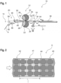
- Figure 1 schematically shows a cardboard processing machine 10 for processing a cardboard web 11.
- the cardboard processing machine 10 comprises a rotary die cutting machine 12, a feeding station 14, a waste ejection station 18 and an acceleration device 20.
- the continuous cardboard web 11 is fed into the cardboard processing machine 10.
- the cardboard web 11 can be unrolled from a cardboard roll by means of an unwinding unit or it can be fed into the rotary die cutting machine 10 directly after exiting a printing machine.
- the printing machine is for example a digital printing machine.
- the rotary die cutting machine 12 comprises a first rotating cylinder 22 and a second rotating cylinder 24.
- Each of the first cylinder 22 and the second cylinder 24 has a cutting, creasing and/or embossing area 26 and a compensation area 28 that extends along the circumference of the respective cylinder 22, 24.
- the rotating cylinders 22, 24 are oriented such that upon rotation the cutting, creasing and/or embossing areas 26 face each other in an operating point 30 at which the cardboard web 11 is cut and/or creased.
- the compensation areas 28 of the rotating cylinders 22, 24 face each other in the same way.
- a flexible die which carries the cutting, creasing and/or embossing means is attached to the rotating cylinders 22, 24 in a magnetic manner.
- the flexible die is not shown in the Figures for reasons of simplicity.
- the die can also be a solid cylinder with adjustable solid plates or other die cutting means as known by the person skilled in the art.
- the cutting, creasing and/or embossing area 26 of only one rotating cylinder 22, 24 carries cutting, creasing and/or embossing means, while the cutting, creasing and/or embossing area 26 of the other cylinder consists of a hardened section.
- the cardboard web 11 is run between the two cylinders 22, 24 in a processing direction in order to be cut and/or creased.
- the processing direction is indicated in Figure 1 by arrow 31.
- the cardboard processing machine 10 In the cardboard processing machine 10 according to the depicted embodiment, cutting and creasing is done in the same rotary die cutting machine 12. However, it is also possible that the cardboard processing machine 12 comprises two rotary die cutting machines, one for cutting and one for creasing.
- the waste material is separated from the cardboard blanks 32 in the waste ejection station 18, which is arranged subsequent to the rotary die cutting machine 12 with respect to a processing direction.
- the waste ejection station 18 comprises at least one deflection device, for example an ejection disk 34 that rolls over the cut cardboard web 11.
- the waste ejection station 18 comprises a plurality of ejection disks 34 that are distributed along a direction transverse to the processing direction of the cardboard web 11.
- the waste ejection station 18 also comprises a shredder 36 in which the ejected cardboard matrix parts are shredded.
- the cardboard blanks 32 are separated from waste, the cardboard blanks 32 are arranged on a conveying belt 38 for further transport.
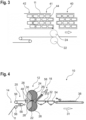
- Figure 2 shows a section of a continuous cardboard web 11.
- the continuous cardboard web 11 is printed with a plurality of repetitive printed sections 40, 41, 42.
- the length of the printed sections 40, 41, 42 differs in different printing jobs. In most cases, a printing length I of a printed section 40, 41, 42 is shorter than a circumference of the rotating cylinders 22, 24.
- the circumferential length of the cutting, creasing and/or embossing area 26 and the compensation area 28 depends on the printing length I of the printed sections.
- the length of the cutting, creasing and/or embossing area 26 and the compensation area 28 are equal. However, this ratio differs for different production jobs.
- the printing length I of a printed section 40, 41, 42 is the length of a print itself plus the distance between two subsequent prints.
- the cardboard web 11 has to be synchronized with the cutting, creasing and/or embossing area 26 of the rotating cylinders 22, 24.
- the cardboard web 11 runs between the two rotating cylinders 22, 24, whereby the cutting, creasing and/or embossing area 26 of the first and the second cylinder 22, 24 rolls over a first printed section 40 of the continuous cardboard web 11 and cuts and/or creases the cardboard web 11 along the first printed section 40.
- transverse cut 44 is a straight cut.
- transverse cut 44 is made along an outline of the printed sections 40, 41, 42. This has the purpose to avoid excessive waste which would occur in case of a straight cut at the beginning and the ending of a blank 32.
- the transverse cut 44 serves to separate the cardboard web 11 into blanks 32.
- the cardboard web 11 is decelerated and pulled back in a direction opposite to the processing direction.
- the cardboard web 11 is pulled back to such an extent that after a full rotation of the rotating cylinders 22, 24 the cutting, creasing and/or embossing area 26 of the rotating cylinders 22, 24 meets the beginning of the second printed section 41, such that the cutting, creasing and/or embossing area 26 of the first and the second cylinder 22, 24 rolls over the second printed section 41 of the continuous cardboard web 11 and cuts and/or creases the cardboard web 11 along the second printed section 41.
- the second printed section 41 is held out of engagement with the rotary die cutting machine 12 until the compensation areas 28 of the cylinders 22, 24 have passed the operation point 30.
- the rotation speed of the cylinders 22, 24 and the travelling speed of the cardboard web 1 should be equal to avoid ripping the cardboard material.
- the rotation speed of the rotating cylinders 22, 24 is constant.
- the cardboard web 11 is moved back and forth in an oscillating manner.
- the transverse cut 44 is omitted. Instead, after cutting, creasing and/or embossing the cardboard web 11 along the first printed section 40, the rotating cylinders 22, 24 roll over the second printed section 41 with the compensation area 28. While the cardboard web 11 is in contact with the compensation area 28, no cutting, creasing and/or embossing of the cardboard web 11 happens. The cardboard web 11 is pulled back before the cutting, creasing and/or embossing area 26 of the rotation cylinders 22, 24 meets the second printed section. Thereby, a synchronization of the cardboard web 11 with the cutting, creasing and/or embossing area 26 is achieved.
- the cardboard processing machine 10 comprises the acceleration device 20.
- the acceleration device 20 is configured to pull back and accelerate the cardboard web 11.
- the acceleration device 20 is arranged preceding to the rotary die cutting machine 12.
- the acceleration device 20 comprises three deflection rollers over which the cardboard web 11 is guided.
- One of the deflection rollers 56 is moveable in order to pull back the cardboard web 11 in a direction opposite to a processing direction.
- the deflection roller 56 is moveable in a horizontal direction.
- the deflection roller 56 is moveable in an oscillating manner.
- the acceleration device 20 also comprises a vacuum belt 46, which is configured to hold the cardboard web 11 such that the cardboard web 11 would not lift off.
- the acceleration device 20 comprises a pressure roll 48 which is arranged at the beginning of a contact area of the vacuum belt 46.
- the pressure roll 48 in particular presses the cardboard web 11 down on the vacuum belt 46.
- the acceleration device does not comprise a vacuum belt but a pressure roll or two rolls only.
- the acceleration device 20 comprises a guide plate 50 that is arranged above the vacuum belt 46.
- the guide plate 50 also contributes to ensuring a proper engagement between the cardboard web 11 and the vacuum belt 46.
- the guide plate 50 exceeds the vacuum belt 46 in a direction towards the rotary die cutting machine 12 such that the guide plate 50 supports feeding the cardboard web into the rotary die cutting machine 12 between the rotating cylinders 22, 24 after a synchronization process.
- the cardboard processing machine 10 may comprise a further vacuum belt 52 which supports pulling the cardboard blanks 32 out of the rotary die cutting machine 12.
- a further vacuum belt 54 is configured for separating the cardboard blanks 32.
- the feeding speed with which the continuous cardboard web 11 is fed into the cardboard processing machine 10 is slower than the rotation speed of the rotating cylinders 22, 24 in order to compensate for the cardboard web 11 being pulled back during the synchronization process.
- FIG. 4 schematically shows a further cardboard processing machine 10.
- the same reference signs are used and reference is made to the preceding explanations.
- the embodiment of Figure 4 differs from the embodiment of Figure 1 in the waste ejection station 18.
- the waste ejection station 18 comprises a matrix rewinder 58 to continuously wind up the matrix.
- the transverse cut 44 is omitted.
- the acceleration device 20 comprises two pressure rolls 48.
Landscapes
- Engineering & Computer Science (AREA)
- Mechanical Engineering (AREA)
- Life Sciences & Earth Sciences (AREA)
- Forests & Forestry (AREA)
- Making Paper Articles (AREA)
Priority Applications (2)
| Application Number | Priority Date | Filing Date | Title |
|---|---|---|---|
| EP23191035.7A EP4506122A1 (fr) | 2023-08-11 | 2023-08-11 | Méthode de découpe, de refoulage et/ou de gaufrage d'un carton et machine de traitement du carton |
| US18/798,362 US20250050613A1 (en) | 2023-08-11 | 2024-08-08 | Method for cutting, creasing and/ or embossing a cardboard and cardboard processing machine |
Applications Claiming Priority (1)
| Application Number | Priority Date | Filing Date | Title |
|---|---|---|---|
| EP23191035.7A EP4506122A1 (fr) | 2023-08-11 | 2023-08-11 | Méthode de découpe, de refoulage et/ou de gaufrage d'un carton et machine de traitement du carton |
Publications (1)
| Publication Number | Publication Date |
|---|---|
| EP4506122A1 true EP4506122A1 (fr) | 2025-02-12 |
Family
ID=87570883
Family Applications (1)
| Application Number | Title | Priority Date | Filing Date |
|---|---|---|---|
| EP23191035.7A Pending EP4506122A1 (fr) | 2023-08-11 | 2023-08-11 | Méthode de découpe, de refoulage et/ou de gaufrage d'un carton et machine de traitement du carton |
Country Status (2)
| Country | Link |
|---|---|
| US (1) | US20250050613A1 (fr) |
| EP (1) | EP4506122A1 (fr) |
Citations (4)
| Publication number | Priority date | Publication date | Assignee | Title |
|---|---|---|---|---|
| DE19836211A1 (de) * | 1998-08-11 | 2000-02-17 | Christian Schade | Rotationsschneideverfahren für Folienbahnen und dergleichen sowie Vorrichtung zur Durchführung des Verfahrens |
| EP1026111A2 (fr) * | 1999-02-05 | 2000-08-09 | Allan R. Prittie | Dispositif d'alimentation d'un appareil de traitment rotatif d'une bande avec diamètre de base fixe |
| US20060096065A1 (en) * | 2003-01-08 | 2006-05-11 | Komori-Chambon Sa | Methods for the preparation of dhea derivatives |
| US20140318340A1 (en) * | 2013-04-26 | 2014-10-30 | Horizon International Inc. | Rotary die cutter |
Family Cites Families (1)
| Publication number | Priority date | Publication date | Assignee | Title |
|---|---|---|---|---|
| US5816720A (en) * | 1994-03-15 | 1998-10-06 | Interbold | Printer mechanism for automated teller machine |
-
2023
- 2023-08-11 EP EP23191035.7A patent/EP4506122A1/fr active Pending
-
2024
- 2024-08-08 US US18/798,362 patent/US20250050613A1/en active Pending
Patent Citations (4)
| Publication number | Priority date | Publication date | Assignee | Title |
|---|---|---|---|---|
| DE19836211A1 (de) * | 1998-08-11 | 2000-02-17 | Christian Schade | Rotationsschneideverfahren für Folienbahnen und dergleichen sowie Vorrichtung zur Durchführung des Verfahrens |
| EP1026111A2 (fr) * | 1999-02-05 | 2000-08-09 | Allan R. Prittie | Dispositif d'alimentation d'un appareil de traitment rotatif d'une bande avec diamètre de base fixe |
| US20060096065A1 (en) * | 2003-01-08 | 2006-05-11 | Komori-Chambon Sa | Methods for the preparation of dhea derivatives |
| US20140318340A1 (en) * | 2013-04-26 | 2014-10-30 | Horizon International Inc. | Rotary die cutter |
Also Published As
| Publication number | Publication date |
|---|---|
| US20250050613A1 (en) | 2025-02-13 |
Similar Documents
| Publication | Publication Date | Title |
|---|---|---|
| US11524422B2 (en) | Method of operating a flat-bed die cutter | |
| JP2928598B2 (ja) | ロールまたはログを形成する巻取機械および方法 | |
| US20120085213A1 (en) | Folder for Adjustably Tensioning a Web as the Web is Cut | |
| CN102985346B (zh) | 用于保护用于加工卷筒纸基材的加工单元的方法、供给站和包装生产机器 | |
| EP3535125B1 (fr) | Machine de laminage pourvu d'un moyen d'insertion et procédé de laminage d'une matière | |
| EP2371526B1 (fr) | Procédé et dispositif d'application de feuilles rigides tranparentes | |
| US10336567B2 (en) | Manufacturing system with flat-bed and rotary diecutters and method for operating the manufacturing system | |
| EP2340171B1 (fr) | Appareil de changement de vitesse par increment pour transporter des produits imprimes dans une plieuse pour machine a imprimer | |
| US7913989B2 (en) | Section for transporting printed products of variable cutoffs in a printing press folder | |
| US5657677A (en) | Apparatus having an interchangeable covering for cutting semi-rigid sheets one by one, in particular sheets of cardboard | |
| EP4506122A1 (fr) | Méthode de découpe, de refoulage et/ou de gaufrage d'un carton et machine de traitement du carton | |
| JP7561158B2 (ja) | アンダーラップ又はオーバーラップするシートの鱗状列流を形成するためのデバイス及び方法 | |
| US11331872B2 (en) | Method for feeding a web of printing material in a manufacturing system for producing packages | |
| EP1026111A2 (fr) | Dispositif d'alimentation d'un appareil de traitment rotatif d'une bande avec diamètre de base fixe | |
| US6615730B2 (en) | Method and apparatus for controlling rotary presses in power failure | |
| US20050061171A1 (en) | System of punching or printing | |
| JPH0976460A (ja) | フォーム印刷機の折り装置における用紙切断装置 | |
| US6669617B1 (en) | Paper web folding and cutting apparatus | |
| US20160221327A1 (en) | Web insertion device for a flat-bed die-cutting machine, manufacturing system for packages and method for feeding a web of printing material | |
| US7845636B2 (en) | Apparatus and method for spatially orienting blanks | |
| US12358744B2 (en) | Method for activating at least one alignment segment of a processing machine | |
| US12351427B2 (en) | Processing machine and method for activating at least one alignment segment of a processing machine | |
| US20200165094A1 (en) | Apparatus and method for positionally defined transport of sheets | |
| CA1326868C (fr) | Traitement du papier et autres materiaux en nappe |
Legal Events
| Date | Code | Title | Description |
|---|---|---|---|
| PUAI | Public reference made under article 153(3) epc to a published international application that has entered the european phase |
Free format text: ORIGINAL CODE: 0009012 |
|
| STAA | Information on the status of an ep patent application or granted ep patent |
Free format text: STATUS: THE APPLICATION HAS BEEN PUBLISHED |
|
| AK | Designated contracting states |
Kind code of ref document: A1 Designated state(s): AL AT BE BG CH CY CZ DE DK EE ES FI FR GB GR HR HU IE IS IT LI LT LU LV MC ME MK MT NL NO PL PT RO RS SE SI SK SM TR |
|
| STAA | Information on the status of an ep patent application or granted ep patent |
Free format text: STATUS: REQUEST FOR EXAMINATION WAS MADE |
|
| 17P | Request for examination filed |
Effective date: 20250811 |